EP0473496A1 - Verfahren zur Herstellung einer monomoden optischen Faser aus elektrooptischem Polymer, sowie eine solche optische Faser - Google Patents
Verfahren zur Herstellung einer monomoden optischen Faser aus elektrooptischem Polymer, sowie eine solche optische Faser Download PDFInfo
- Publication number
- EP0473496A1 EP0473496A1 EP91402282A EP91402282A EP0473496A1 EP 0473496 A1 EP0473496 A1 EP 0473496A1 EP 91402282 A EP91402282 A EP 91402282A EP 91402282 A EP91402282 A EP 91402282A EP 0473496 A1 EP0473496 A1 EP 0473496A1
- Authority
- EP
- European Patent Office
- Prior art keywords
- polymer
- core
- tube
- optical waveguide
- optical
- Prior art date
- Legal status (The legal status is an assumption and is not a legal conclusion. Google has not performed a legal analysis and makes no representation as to the accuracy of the status listed.)
- Granted
Links
- 229920000642 polymer Polymers 0.000 title claims abstract description 76
- 230000003287 optical effect Effects 0.000 title claims abstract description 49
- 238000004519 manufacturing process Methods 0.000 title claims abstract description 15
- 238000000034 method Methods 0.000 title claims description 30
- 230000008569 process Effects 0.000 title claims description 14
- 239000000126 substance Substances 0.000 claims abstract description 21
- 239000000203 mixture Substances 0.000 claims abstract description 20
- 239000013543 active substance Substances 0.000 claims abstract description 12
- 238000006116 polymerization reaction Methods 0.000 claims abstract description 12
- 230000005284 excitation Effects 0.000 claims abstract description 10
- 239000011248 coating agent Substances 0.000 claims abstract description 3
- 238000000576 coating method Methods 0.000 claims abstract description 3
- 239000000835 fiber Substances 0.000 claims description 15
- 239000000178 monomer Substances 0.000 claims description 14
- 230000005684 electric field Effects 0.000 claims description 12
- 230000000694 effects Effects 0.000 claims description 10
- 230000009471 action Effects 0.000 claims description 9
- 230000010287 polarization Effects 0.000 claims description 9
- 230000009477 glass transition Effects 0.000 claims description 7
- FXPHJTKVWZVEGA-UHFFFAOYSA-N ethenyl hydrogen carbonate Chemical class OC(=O)OC=C FXPHJTKVWZVEGA-UHFFFAOYSA-N 0.000 claims description 6
- 229910001092 metal group alloy Inorganic materials 0.000 claims description 5
- 238000005253 cladding Methods 0.000 claims description 4
- 238000004132 cross linking Methods 0.000 claims description 4
- 230000008018 melting Effects 0.000 claims description 4
- 238000002844 melting Methods 0.000 claims description 4
- 150000004649 carbonic acid derivatives Chemical class 0.000 claims description 3
- 239000003795 chemical substances by application Substances 0.000 claims description 3
- 125000005395 methacrylic acid group Chemical group 0.000 claims description 3
- 238000002360 preparation method Methods 0.000 claims description 3
- 238000001704 evaporation Methods 0.000 claims description 2
- 230000008020 evaporation Effects 0.000 claims description 2
- -1 ester methacrylate Chemical class 0.000 claims 2
- 125000003011 styrenyl group Chemical class [H]\C(*)=C(/[H])C1=C([H])C([H])=C([H])C([H])=C1[H] 0.000 claims 2
- 239000013307 optical fiber Substances 0.000 abstract description 12
- VYPSYNLAJGMNEJ-UHFFFAOYSA-N Silicium dioxide Chemical compound O=[Si]=O VYPSYNLAJGMNEJ-UHFFFAOYSA-N 0.000 description 12
- XTTIQGSLJBWVIV-UHFFFAOYSA-N 2-methyl-4-nitroaniline Chemical compound CC1=CC([N+]([O-])=O)=CC=C1N XTTIQGSLJBWVIV-UHFFFAOYSA-N 0.000 description 9
- 239000000463 material Substances 0.000 description 9
- 230000005374 Kerr effect Effects 0.000 description 8
- 230000003993 interaction Effects 0.000 description 8
- 230000005693 optoelectronics Effects 0.000 description 7
- 230000005697 Pockels effect Effects 0.000 description 6
- 239000000377 silicon dioxide Substances 0.000 description 6
- 238000004821 distillation Methods 0.000 description 4
- 229920003229 poly(methyl methacrylate) Polymers 0.000 description 4
- 239000004926 polymethyl methacrylate Substances 0.000 description 4
- 230000009021 linear effect Effects 0.000 description 3
- 241001080024 Telles Species 0.000 description 2
- WQAQPCDUOCURKW-UHFFFAOYSA-N butanethiol Chemical compound CCCCS WQAQPCDUOCURKW-UHFFFAOYSA-N 0.000 description 2
- 238000006243 chemical reaction Methods 0.000 description 2
- 238000010586 diagram Methods 0.000 description 2
- 230000006870 function Effects 0.000 description 2
- 238000003801 milling Methods 0.000 description 2
- 239000013308 plastic optical fiber Substances 0.000 description 2
- 125000000954 2-hydroxyethyl group Chemical group [H]C([*])([H])C([H])([H])O[H] 0.000 description 1
- AKFIUPCAMXNHFX-UHFFFAOYSA-N 5-nitro-2-phenyldiazenylaniline Chemical compound NC1=CC([N+]([O-])=O)=CC=C1N=NC1=CC=CC=C1 AKFIUPCAMXNHFX-UHFFFAOYSA-N 0.000 description 1
- JBRZTFJDHDCESZ-UHFFFAOYSA-N AsGa Chemical compound [As]#[Ga] JBRZTFJDHDCESZ-UHFFFAOYSA-N 0.000 description 1
- FOQABOMYTOFLPZ-ISLYRVAYSA-N Disperse Red 1 Chemical compound C1=CC(N(CCO)CC)=CC=C1\N=N\C1=CC=C([N+]([O-])=O)C=C1 FOQABOMYTOFLPZ-ISLYRVAYSA-N 0.000 description 1
- 229910001218 Gallium arsenide Inorganic materials 0.000 description 1
- 240000002329 Inga feuillei Species 0.000 description 1
- 229910003327 LiNbO3 Inorganic materials 0.000 description 1
- LSDPWZHWYPCBBB-UHFFFAOYSA-N Methanethiol Chemical compound SC LSDPWZHWYPCBBB-UHFFFAOYSA-N 0.000 description 1
- VVQNEPGJFQJSBK-UHFFFAOYSA-N Methyl methacrylate Chemical compound COC(=O)C(C)=C VVQNEPGJFQJSBK-UHFFFAOYSA-N 0.000 description 1
- 230000006978 adaptation Effects 0.000 description 1
- 229910045601 alloy Inorganic materials 0.000 description 1
- 239000000956 alloy Substances 0.000 description 1
- 230000008901 benefit Effects 0.000 description 1
- 230000005540 biological transmission Effects 0.000 description 1
- 230000015572 biosynthetic process Effects 0.000 description 1
- 230000008859 change Effects 0.000 description 1
- 239000003153 chemical reaction reagent Substances 0.000 description 1
- 230000001143 conditioned effect Effects 0.000 description 1
- 239000004020 conductor Substances 0.000 description 1
- 229920000547 conjugated polymer Polymers 0.000 description 1
- 239000000470 constituent Substances 0.000 description 1
- 239000013078 crystal Substances 0.000 description 1
- WNAHIZMDSQCWRP-UHFFFAOYSA-N dodecane-1-thiol Chemical compound CCCCCCCCCCCCS WNAHIZMDSQCWRP-UHFFFAOYSA-N 0.000 description 1
- 150000002148 esters Chemical class 0.000 description 1
- SUPCQIBBMFXVTL-UHFFFAOYSA-N ethyl 2-methylprop-2-enoate Chemical compound CCOC(=O)C(C)=C SUPCQIBBMFXVTL-UHFFFAOYSA-N 0.000 description 1
- 238000012681 fiber drawing Methods 0.000 description 1
- 230000005764 inhibitory process Effects 0.000 description 1
- 229910052500 inorganic mineral Inorganic materials 0.000 description 1
- GQYHUHYESMUTHG-UHFFFAOYSA-N lithium niobate Chemical compound [Li+].[O-][Nb](=O)=O GQYHUHYESMUTHG-UHFFFAOYSA-N 0.000 description 1
- 238000003754 machining Methods 0.000 description 1
- 125000002496 methyl group Chemical group [H]C([H])([H])* 0.000 description 1
- 239000011707 mineral Substances 0.000 description 1
- IXYATCDSDHQBLY-UHFFFAOYSA-N n,n-diethyl-4-[2-(4-nitrophenyl)ethenyl]aniline Chemical compound C1=CC(N(CC)CC)=CC=C1C=CC1=CC=C([N+]([O-])=O)C=C1 IXYATCDSDHQBLY-UHFFFAOYSA-N 0.000 description 1
- 230000009022 nonlinear effect Effects 0.000 description 1
- 125000000962 organic group Chemical group 0.000 description 1
- 230000010363 phase shift Effects 0.000 description 1
- 229920000015 polydiacetylene Polymers 0.000 description 1
- 239000003505 polymerization initiator Substances 0.000 description 1
- 230000000135 prohibitive effect Effects 0.000 description 1
- 238000000746 purification Methods 0.000 description 1
- 230000009467 reduction Effects 0.000 description 1
- 239000012779 reinforcing material Substances 0.000 description 1
- 230000004044 response Effects 0.000 description 1
- 230000035945 sensitivity Effects 0.000 description 1
- 239000002904 solvent Substances 0.000 description 1
- 230000006641 stabilisation Effects 0.000 description 1
- 238000011105 stabilization Methods 0.000 description 1
- 150000003440 styrenes Chemical class 0.000 description 1
- 230000009466 transformation Effects 0.000 description 1
Images


Classifications
-
- B—PERFORMING OPERATIONS; TRANSPORTING
- B29—WORKING OF PLASTICS; WORKING OF SUBSTANCES IN A PLASTIC STATE IN GENERAL
- B29D—PRODUCING PARTICULAR ARTICLES FROM PLASTICS OR FROM SUBSTANCES IN A PLASTIC STATE
- B29D11/00—Producing optical elements, e.g. lenses or prisms
- B29D11/00663—Production of light guides
- B29D11/00721—Production of light guides involving preforms for the manufacture of light guides
-
- G—PHYSICS
- G02—OPTICS
- G02F—OPTICAL DEVICES OR ARRANGEMENTS FOR THE CONTROL OF LIGHT BY MODIFICATION OF THE OPTICAL PROPERTIES OF THE MEDIA OF THE ELEMENTS INVOLVED THEREIN; NON-LINEAR OPTICS; FREQUENCY-CHANGING OF LIGHT; OPTICAL LOGIC ELEMENTS; OPTICAL ANALOGUE/DIGITAL CONVERTERS
- G02F1/00—Devices or arrangements for the control of the intensity, colour, phase, polarisation or direction of light arriving from an independent light source, e.g. switching, gating or modulating; Non-linear optics
- G02F1/01—Devices or arrangements for the control of the intensity, colour, phase, polarisation or direction of light arriving from an independent light source, e.g. switching, gating or modulating; Non-linear optics for the control of the intensity, phase, polarisation or colour
- G02F1/061—Devices or arrangements for the control of the intensity, colour, phase, polarisation or direction of light arriving from an independent light source, e.g. switching, gating or modulating; Non-linear optics for the control of the intensity, phase, polarisation or colour based on electro-optical organic material
- G02F1/065—Devices or arrangements for the control of the intensity, colour, phase, polarisation or direction of light arriving from an independent light source, e.g. switching, gating or modulating; Non-linear optics for the control of the intensity, phase, polarisation or colour based on electro-optical organic material in an optical waveguide structure
Definitions
- the present invention relates to a method of manufacturing a single-mode cylindrical optical waveguide made of polymer, such a waveguide allowing modulation, by electrooptic effect, of the light wave which it transmits. It also relates to such a waveguide endowed with electrooptical properties.
- the invention finds a particularly advantageous application in the field of telecommunications by optical fibers, and, in particular, in that of optical fibers operating in the near infrared, for example between 0.6 ⁇ m and 2 ⁇ m.
- the general technical problem which arises in all telecommunications devices by optical fibers is to transmit the information which one wishes to convey, in the form of a phase or amplitude modulation of the carrier wave, here the light wave. It is therefore necessary to have means capable of producing the desired modulation, or, more generally, of modifying the properties of propagation of light in a network of optical fibers.
- a known solution to this technical problem consists in using the non-linear properties of the electrical susceptibility of certain materials.
- the application of a strong electric field on a material of this type causes a variation in the refractive index of the medium which modifies the phase of the light wave. If this field is modulated, the system operates as a phase or amplitude modulator by interference with a fixed phase wave.
- Electrooptical modulators are known which are made from mineral single crystals, such as KDP, lithium niobate (LiNbO3) or gallium arsenide for example.
- these materials are of a crystallogenesis often difficult to implement, and, moreover, they generally require to be conditioned in the form of optical waveguides in order to be able to be integrated into a set of telecommunications by fibers. This is why these components, although very effective, are very expensive, their price being prohibitive for their use in a network of optical fibers.
- the modulation functions are sometimes performed at the source, that is to say by direct modulation, with the disadvantage that the electrooptical conversions far from the transmitters are limited.
- polymer optical fibers an advantageous embodiment of which is given in French Patent No. 2,557,495, offers new interesting possibilities with a view to obtaining optical waveguides with intense electrooptical effects, in the extent that organic molecules, such as 2 Methyl 4-Nitroaniline, DEANS (4-diethylamino-4′-nitrostilbene), Disperse Red 1 (4- [N-ethyl-N- (2-hydroxyethyl)] amino- 4′-nitroazobenzene), NPP N- (4-nitrophenyl-L-piolinol), or others still, can present nonlinear electrical susceptibilities of two orders of magnitude greater than those of silica for example.
- the unpublished French patent application No. 90 00919 refers to a process for manufacturing a single-mode polymer optical fiber, no description has been given of such fibers capable of producing electrooptical effects.
- the technical problem to be solved by the object of the present invention is to propose a method for manufacturing a single-mode cylindrical optical waveguide made of polymer, in accordance with the preamble, which would make it possible to obtain such a waveguide.
- optic having a strong electrooptical power, while ensuring the geometrical characteristics compatible with the unimodality and while respecting the requirements of the connectability to the standard monomode optical fibers in silica, namely essentially the concentricity of the core of the guide relative to the guide itself .
- fiberizing of a tube will be understood to mean reducing the diameter of said tube to the dimensions of an optical fiber by hot drawing.
- the optical waveguide produced according to the process which is the subject of the invention is relatively inexpensive Student.
- the electrooptical properties of the active organic substance can be very important, it is possible, for the same effect, to significantly reduce the interaction length corresponding to a given peak control voltage, or conversely to decrease the voltage peak for a given interaction length.
- Another advantage offered by the possibility of having a strong electrooptical power lies in the considerable increase in the bandwidth of the optical waveguide which, under certain conditions, could exceed the gigahertz.
- the method according to the invention leads to a single-mode optical waveguide having excellent concentricity of the diameters of the core and of the guide, meeting the conditions for adaptation to the "optical fiber" connectors used in standard manner.
- the electrooptical effects considered here are of two types: the Pockels effect which brings into play the electrical susceptibility of order 2, X (2) , of the material and produces a variation of index of the medium proportional to X (2) E, E being the applied electric field, while the variation of index resulting from the Kerr effect is proportional to X (3) E2, X (3) being the susceptibility of order 3 of the material.
- the effects of order 3 are insufficient or sometimes masked by non-electronic phenomena that are not fast enough, as in polar molecules for example. This is why it is advantageous, in particular in order to be able to modulate the light at high frequency, to reinforce the quadratic properties of the active substance in favor of the electrooptic Pokels effect.
- the molecules of the electrooptically active organic substance inside the core are oriented at a temperature close to the glass transition temperature of the core polymer under the action an electric field which is then maintained until the room temperature returns.
- the polymers which can be used to constitute the core of the optical waveguide are, for example, methacrylic polymers, polymethylmethacrylate in particular, ⁇ -haloacrylates, styrenic polymers, carbonates and vinyl carbonates, which have a temperature glass transition Tg greater than 80 ° C and a fiberizing temperature between 150 and 300 ° C.
- the electrooptically active organic substance must have significant electrical sensitivities of order 2 or 3.
- This type of substance is characterized by a strongly electron donating group linked to an attracting group by a conjugated system which, therefore, has a high susceptibility X (2) , or by strongly conjugated molecules such as polyalkylthiophenes, polydiacetylenes and other conjugated polymers that exhibit significant electronic X (3) susceptibility.
- active substances can be simple molecules or monomers copolymerizable with the monomer of the heart. In both cases, the active molecule must be soluble in the core monomer up to the amount necessary to ensure the effectiveness of the final polymer. Care must be taken that the electrooptically active substance does not inhibit polymerization, does not change during polymerization, and does not cause crosslinking of the polymer of heart in formation or already formed, during fiber drawing for example.
- the active organic substance can be added to the core polymer in different ways: either by simple physical addition to the polymer, this is called “guest-host” structures, or by chemical grafting on the polymer or the monomer to be polymerized.
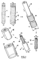
- Figure 1 is a schematic representation of the steps of the method according to the invention.
- FIG. 2 gives the diagram of two modes of implementation of a light guide produced using the method according to the invention.
- FIG. 3 is a perspective view of a light guide having polarization and excitation electrodes deposited on flat areas.
- the process for manufacturing a single-mode cylindrical optical waveguide made of polymer, such a waveguide allowing modulation, by electrooptic effect, of the light wave which it transmits comprises a first step of producing a cylindrical bar 11 of the heart by polymerization of a polymerizable mixture comprising in particular a heart polymer and an electrooptically active organic substance such that the heart has an optical activity under the action of a field electric outdoor.
- the core polymer is produced, for example, from a mixture of two monomers: methylmethacrylate and ethylmethacrylate in an amount of 100/0 to 80/20 moles per mole.
- the electrooptically active substance is generally composed of a molecule such that the core polymer has a second order susceptibility greater than 3.3. 10 ⁇ 14 MKSA, after an orientation operation described in detail below, or a third-order susceptibility greater than 1,1.10 ⁇ 19 MKSA, at the wavelength considered.
- MNA 2-Methyl 4-Nitro-aniline
- MNA is sublimated at a rate of approximately 1 g / h at 90 ° C. and under 2.10 ⁇ 5 mbar, then is introduced into the purification ramp, as described in French patent No. 2,557,495, which is included by reference in the this request.
- the rate of unaccompanied minors can be chosen between 1 and 15% by weight of core polymer formed, and preferably between 5 and 10%.
- a mixture of 5% of MNA in polymethylmethacrylate has an X (3) susceptibility of 5.5.10 ⁇ 21 MKSA against 3.3.10 ⁇ 23 MKSA for silica at around 1 ⁇ m optical wavelength .
- the polymerizable mixture also contains reagents such as a polymerization initiator, ditertiobutylperoxide at a rate of 0.1 to 10 per thousand mole per mole of comonomers, and a transfer agent acting as a trap for free radicals which could attack the MNA.
- reagents such as a polymerization initiator, ditertiobutylperoxide at a rate of 0.1 to 10 per thousand mole per mole of comonomers, and a transfer agent acting as a trap for free radicals which could attack the MNA.
- the transfer agent which may for example be a mercaptan such as laurylmercaptan or n-butylmercaptan, must be dosed so as to avoid inhibition of polymerization by MNA, crosslinking and transformation of the active sites.
- the cylindrical bar 11 of the core preferably has a diameter D1 of 5 mm. If the initial diameter is greater than this value, the bar is drawn hot to reduce its diameter to 5 mm.
- ⁇ is the wavelength
- n c and n g the respective indices of the core and the cladding and d c the final diameter of the core.
- the difference in index n c - n g must be at most 5.10 ⁇ 3.
- MNA increases the index of the polymer to which it has been added. We can therefore predict that the sheath polymer is identical to the core polymer, the MNA sufficient to provide the different index n c -n g necessary. It is also possible to obtain the sheath polymer by polymerization of the polymerizable core mixture, copolymerized with a monomer having a very low refractive index such as a fluorinated ester methatrylate, a pentafluorinated styrene or a fluorinated vinylcarbonate, the quantity of which is adjusted so that n c -n g is close to the desired value.
- a monomer having a very low refractive index such as a fluorinated ester methatrylate, a pentafluorinated styrene or a fluorinated vinylcarbonate
- the ratio of diameters D2 / D1 is greater than or equal to 2 so that the purified optical cladding covers the entire propagation mode.
- D2 / D1 must be less than a certain limit: if the core polymer is polymethyl methacrylate and if the sheath polymer is a comonomer based on methyl methatrylate at more than 90% for example, D2 / D1 must be less than 5.
- the first preform 10 is then fitted into a first tube 20 of internal diameter D2 and of external diameter D3, made of a third polymer, called a tube polymer.
- the tube polymers used must have fiber and glass transition temperatures compatible with those of the core polymer. There are no special conditions on their refractive index, as they only serve as reinforcing material.
- the ratio D3 / D2 is chosen at least equal to 1.25.
- a second preform 30 (FIG. 1d) of diameter D4 is then produced by partial stretching of the first tube 20 containing the first preform 10.
- the final diameter D4 is taken at least equal to 4 mm, 5 mm for example.
- the second preform 30 is in turn fitted (FIG. 1 a) into a second tube 40 of internal diameter D4 and external diameter D5, made of tube polymer.
- the preform obtained 40 then undergoes a preparation intended to arrange means for positioning the polarization electrodes of the electrooptically active substance.
- said positioning means are diametrically opposite flats 41 and 42, obtained by milling the tube 40.
- milling reduces the second tube 40 to a plate from 3.6 to 11 mm thick. This plate is then fiberized (step not shown) at temperatures of the order of 200 to 240 ° C.
- a last step of the method aims to produce the polarization electrodes, for example by metallic evaporation under vacuum on the flats of the monomode fiber obtained.
- FIG. 3 shows such a fiber provided with its polarization and excitation electrodes.
- the means for placing the electrodes are symmetrical holes 43, 44 drilled parallel to the axis of the second tube 40.
- an alloy low melting point conductor such as InGa for example, is introduced into the holes so as to constitute the polarization electrodes.
- said metal alloy has a melting point below at least 20 ° C and at most 40 ° C at the glass transition temperature of the sheath polymer.
- FIG. 2 shows two assembly diagrams in which an optical waveguide 100, produced in accordance with the method described with reference to FIG. 1, is used so as to produce a modulation, by electrooptical effect, of a light wave transmitted along a network of optical fibers.
- FIG. 2a is a phase modulation device comprising a source 101 emitting a wave whose amplitude is given by Ao e j ⁇ t
- This wave is sent in a first optical fiber 102 connected, by a connector 104, to the optical waveguide 100 shown in dotted lines.
- the guide 100 is subjected over a length L to an electric field generated by the variable voltage V (t) applied to the electrodes 51, 52.
- V (t) applied to the electrodes 51, 52.
- the electrooptical effect arising inside the guide 100 produces a phase variation of the light wave, so that the amplitude of the light at the photodetector 108, after transmission along the fiber 107 connected to the guide by the connector 105, is written
- A Ao j ( ⁇ t + ⁇ )
- ⁇ 2 ⁇ Po) LE (t) Po being the Pockels constant involving the order 2 susceptibility, X (2) , of the material.
- the Pockels effect with these materials will be more efficient (low control voltage and high bandwidth because the electrooptic interaction length is shorter and because the phenomena can be purely electronic), but it requires a prior orientation of non-linear organic groups and stabilization of this orientation.
- the phase modulation resulting from the assembly of Figure 2a) can be transformed into intensity modulation by interference between the wave having passed through the optical waveguide 100 and a reference wave transmitted by an optical fiber 109 placed in parallel on the guide between a first 103 and a second 106 couplers.
- the Pockels effect With a view to achieving the widest possible bandwidth, it is preferable to use the Pockels effect rather than the Kerr effect, limited in frequency to a few megahertz.
- the Pockels effect bringing into play the susceptibility of order 2 which is only accessible in non-controsymmetric media, it is generally necessary, after obtaining the monomode fiber, to direct the molecules of the electrooptically active substance hot inside the heart, for example at 80 ° C. for 24 hours in polymethylmethacrylate, under an electric field of 0.5 MV / cm which is maintained until the temperature returns to room temperature. It is thus possible to obtain a 100% modulation with 10 cm of length L of interaction, 20 ⁇ m of spacing between the electrodes and 10 to 20 V of control voltage, at 1 ⁇ m of wavelength.
- the material thus oriented is preferably stabilized by crosslinking between the chains carrying the active molecules.
- This control voltage can drop to 2 V with polymer systems described by L. Li et al in the article "An all fiber electrooptic Kerr modulation” published in IEEE Colloquium on "Advanced fiber waveguide devices” N ° 1986/79, London, 20 May 1986.
Landscapes
- Physics & Mathematics (AREA)
- Engineering & Computer Science (AREA)
- Nonlinear Science (AREA)
- Health & Medical Sciences (AREA)
- Manufacturing & Machinery (AREA)
- Ophthalmology & Optometry (AREA)
- Mechanical Engineering (AREA)
- General Physics & Mathematics (AREA)
- Optics & Photonics (AREA)
- Optical Fibers, Optical Fiber Cores, And Optical Fiber Bundles (AREA)
- Addition Polymer Or Copolymer, Post-Treatments, Or Chemical Modifications (AREA)
- Optical Integrated Circuits (AREA)
Applications Claiming Priority (2)
| Application Number | Priority Date | Filing Date | Title |
|---|---|---|---|
| FR9010635A FR2666046B1 (fr) | 1990-08-24 | 1990-08-24 | Procede de fabrication de composants electrooptiques dans des guides d'onde optique cylindriques monomodes en polymere. |
| FR9010635 | 1990-08-24 |
Publications (2)
| Publication Number | Publication Date |
|---|---|
| EP0473496A1 true EP0473496A1 (de) | 1992-03-04 |
| EP0473496B1 EP0473496B1 (de) | 1995-07-05 |
Family
ID=9399838
Family Applications (1)
| Application Number | Title | Priority Date | Filing Date |
|---|---|---|---|
| EP91402282A Expired - Lifetime EP0473496B1 (de) | 1990-08-24 | 1991-08-21 | Verfahren zur Herstellung einer monomoden optischen Faser aus elektrooptischem Polymer, sowie eine solche optische Faser |
Country Status (4)
| Country | Link |
|---|---|
| US (1) | US5182783A (de) |
| EP (1) | EP0473496B1 (de) |
| DE (1) | DE69110992T2 (de) |
| FR (1) | FR2666046B1 (de) |
Cited By (2)
| Publication number | Priority date | Publication date | Assignee | Title |
|---|---|---|---|---|
| EP0664463A4 (de) * | 1993-06-16 | 1997-08-20 | Sumitomo Electric Industries | Grundmaterial für optische fasern aus kunststoff, sowie verfahren und vorrichtung zu dessen herstellung. |
| EP0662620A4 (de) * | 1993-06-18 | 1997-08-20 | Sumitomo Electric Industries | Verfahren und vorrichtung zur herstellung eines basismaterials für optischen fasern. |
Families Citing this family (18)
| Publication number | Priority date | Publication date | Assignee | Title |
|---|---|---|---|---|
| JPH05173210A (ja) * | 1991-12-24 | 1993-07-13 | Hoechst Japan Ltd | 周波数変換素子及びその製造方法 |
| US5818983A (en) * | 1992-03-06 | 1998-10-06 | Fujitsu Limited | Optical integrated circuit, optical circuit waveguide device and process for oriented, selective growth and formation of organic film |
| US5259059A (en) * | 1992-12-10 | 1993-11-02 | Xerox Corporation | Optical fibers with built-in alignment features |
| US5639512A (en) * | 1993-06-18 | 1997-06-17 | Sumitomo Electric Industries, Ltd. | Plastic optical fiber preform, and process and apparatus for producing the same |
| AU8129394A (en) * | 1993-10-28 | 1995-05-22 | Valeriy S. Maisotsenko | Method of determining working media motion and designing flow structures for same |
| KR0177088B1 (ko) | 1993-11-29 | 1999-05-15 | 김광호 | 단일모드 광섬유 1차 모재 오버크래딩 방법 및 장치 |
| US5479551A (en) * | 1994-08-29 | 1995-12-26 | At&T Corp. | Optical fiber non-reciprocal phase shifters and optical isolators using them |
| US5768462A (en) * | 1996-03-05 | 1998-06-16 | Kvh Industries, Inc. | Grooved optical fiber for use with an electrode and a method for making same |
| DE19720598A1 (de) * | 1997-05-16 | 1998-11-19 | Siemens Ag | Verfahren zum Anschneiden von Lichtwellenleiterkabeln und Vorrichtung zur Durchführung des Verfahrens |
| US6240226B1 (en) * | 1998-08-13 | 2001-05-29 | Lucent Technologies Inc. | Polymer material and method for optical switching and modulation |
| US6574408B2 (en) * | 2000-09-14 | 2003-06-03 | Universite De Liege | Monomode optical fibre |
| WO2003005081A1 (en) * | 2001-07-02 | 2003-01-16 | Acreo Ab | Method and device for controlling the refractive index in an optical fiber |
| AUPR667701A0 (en) * | 2001-07-27 | 2001-08-23 | Redfern Polymer Optics Pty Ltd | Materials for polymer optical fibers |
| KR100403673B1 (ko) * | 2001-12-12 | 2003-10-30 | 한국전자통신연구원 | 광섬유 상의 상호 절연된 두 도전막 형성방법 |
| EP1741546B1 (de) * | 2002-04-16 | 2009-03-25 | Prysmian S.p.A. | Verfahren zur Herstellung von einer mikrostrukturierten optischen Faser |
| US6931164B2 (en) * | 2002-11-20 | 2005-08-16 | Optimer Photonics, Inc. | Waveguide devices incorporating Kerr-based and other similar optically functional mediums |
| CN112198585B (zh) * | 2020-09-01 | 2021-05-18 | 威海长和光导科技有限公司 | 一种单模阶跃型聚合物光纤及其制备方法 |
| CN114935837B (zh) * | 2022-05-25 | 2024-12-31 | 暨南大学 | 一种全光纤电光调制器及制备方法 |
Citations (5)
| Publication number | Priority date | Publication date | Assignee | Title |
|---|---|---|---|---|
| EP0151363A1 (de) * | 1983-12-29 | 1985-08-14 | Dominique Bosc | Verfahren zur Herstellung eines Formlings für polymerische, optische Faser, mit Indexsprung, derartig hergestellter Formling und dessen Verwendung |
| EP0232138A2 (de) * | 1986-01-30 | 1987-08-12 | The British Petroleum Company p.l.c. | Polymerzusammensetzungen |
| WO1988002131A1 (en) * | 1986-09-19 | 1988-03-24 | Aktieselskabet Nordiske Kabel- Og Traadfabriker | A process for producing an electrooptical material having controllable-properties, and use of the material in electrooptical components |
| EP0265921A2 (de) * | 1986-10-31 | 1988-05-04 | Hoechst Celanese Corporation | Nicht-lineare optische Vorrichtungen |
| WO1989003054A1 (en) * | 1987-09-18 | 1989-04-06 | David S Soane | Field-assisted fiber spinning for the preparation of optical fibers having non-linear optical activity |
Family Cites Families (1)
| Publication number | Priority date | Publication date | Assignee | Title |
|---|---|---|---|---|
| US5076658A (en) * | 1990-04-30 | 1991-12-31 | Unisys Corporation | Non-linear optical polymeric fiber waveguides |
-
1990
- 1990-08-24 FR FR9010635A patent/FR2666046B1/fr not_active Expired - Fee Related
-
1991
- 1991-08-21 DE DE69110992T patent/DE69110992T2/de not_active Expired - Fee Related
- 1991-08-21 EP EP91402282A patent/EP0473496B1/de not_active Expired - Lifetime
- 1991-08-22 US US07/748,701 patent/US5182783A/en not_active Expired - Lifetime
Patent Citations (5)
| Publication number | Priority date | Publication date | Assignee | Title |
|---|---|---|---|---|
| EP0151363A1 (de) * | 1983-12-29 | 1985-08-14 | Dominique Bosc | Verfahren zur Herstellung eines Formlings für polymerische, optische Faser, mit Indexsprung, derartig hergestellter Formling und dessen Verwendung |
| EP0232138A2 (de) * | 1986-01-30 | 1987-08-12 | The British Petroleum Company p.l.c. | Polymerzusammensetzungen |
| WO1988002131A1 (en) * | 1986-09-19 | 1988-03-24 | Aktieselskabet Nordiske Kabel- Og Traadfabriker | A process for producing an electrooptical material having controllable-properties, and use of the material in electrooptical components |
| EP0265921A2 (de) * | 1986-10-31 | 1988-05-04 | Hoechst Celanese Corporation | Nicht-lineare optische Vorrichtungen |
| WO1989003054A1 (en) * | 1987-09-18 | 1989-04-06 | David S Soane | Field-assisted fiber spinning for the preparation of optical fibers having non-linear optical activity |
Non-Patent Citations (2)
| Title |
|---|
| APPLIED OPTICS vol. 20, no. 8, Avril 1981, pages 1403 - 1406; J.M.DZIEDZIC ET ALIA: 'OPTICAL KERR EFFECT IN LONG FIBERS' * |
| GLASS TECHNOLOGY vol. 28, no. 1, Février 1987, SHEFFIELD pages 38 - 42; POIGNANT ET ALIA: 'THE PREPARATION OF FLUORIDE GLASS SINGLE MODE FIBRES' * |
Cited By (2)
| Publication number | Priority date | Publication date | Assignee | Title |
|---|---|---|---|---|
| EP0664463A4 (de) * | 1993-06-16 | 1997-08-20 | Sumitomo Electric Industries | Grundmaterial für optische fasern aus kunststoff, sowie verfahren und vorrichtung zu dessen herstellung. |
| EP0662620A4 (de) * | 1993-06-18 | 1997-08-20 | Sumitomo Electric Industries | Verfahren und vorrichtung zur herstellung eines basismaterials für optischen fasern. |
Also Published As
| Publication number | Publication date |
|---|---|
| US5182783A (en) | 1993-01-26 |
| DE69110992T2 (de) | 1995-11-23 |
| FR2666046A1 (fr) | 1992-02-28 |
| DE69110992D1 (de) | 1995-08-10 |
| FR2666046B1 (fr) | 1994-07-08 |
| EP0473496B1 (de) | 1995-07-05 |
Similar Documents
| Publication | Publication Date | Title |
|---|---|---|
| EP0473496B1 (de) | Verfahren zur Herstellung einer monomoden optischen Faser aus elektrooptischem Polymer, sowie eine solche optische Faser | |
| EP0797113A1 (de) | Aktiver integriert optischer Silizium-Polymermischungs-Richtkoppler | |
| Tanaka et al. | Ultra-small, self-holding, optical gate switch using Ge2Sb2Te5 with a multi-mode Si waveguide | |
| EP0129463B1 (de) | Integrierte optische polarisierende Anordnung und Verfahren zu ihrer Herstellung | |
| Stiller et al. | Coherently refreshing hypersonic phonons for light storage | |
| GB2220080A (en) | Improvements in optical waveguides | |
| Lee et al. | Polymeric tunable optical attenuator with an optical monitoring tap for WDM transmission network | |
| EP0451047A1 (de) | Vor Umwelteinflüssen geschützte integrierte optische Komponente und Verfahren zu ihrer Herstellung | |
| FR2514155A1 (fr) | Fibre optique monomode a faible dispersion | |
| Huang et al. | High-performance and compact integrated photonics platform based on silicon rich nitride–lithium niobate on insulator | |
| Kaino | Waveguide fabrication using organic nonlinear optical materials | |
| FR2694819A1 (fr) | Dispositif d'adaptation de vitesse entre des signaux élkectriques et optiques. | |
| Shi et al. | Double-end crosslinked electro-optic polymer modulators with high optical power handling capability | |
| Tumolillo et al. | A novel pulse-poling technique for EO polymer waveguide devices using device electrode poling | |
| Takizawa et al. | Polarization-independent optical fiber modulator by use of polymer-dispersed liquid crystals | |
| Watanabe et al. | Novel ‘‘serially grafted’’connection between functional and passive polymer waveguides | |
| Tian et al. | Polymer/silica hybrid integration add-drop filter based on grating-assisted contradirectional coupler | |
| Han et al. | Improved method for hot embossing As2S3 waveguides employing a thermally stable chalcogenide coating | |
| EP0387740B1 (de) | Optische Faser zur Frequenzumwandlung | |
| Lee et al. | Fabrication and characterization of an electro-optic polymer waveguide modulator for photonic applications | |
| FR2780520A1 (fr) | Modulateur d'intensite optique et son procede de fabrication | |
| FR2657556A1 (fr) | Procede de fabrication de guides optiques circulaires monomodes en polymere. | |
| Lee et al. | Integrated optical polarization splitter based on photobleaching-induced birefringence in azo dye polymers | |
| Wei et al. | Fabrication of lithium niobate optical channel waveguides by nickel indiffusion | |
| CN114935837A (zh) | 一种全光纤电光调制器及制备方法 |
Legal Events
| Date | Code | Title | Description |
|---|---|---|---|
| PUAI | Public reference made under article 153(3) epc to a published international application that has entered the european phase |
Free format text: ORIGINAL CODE: 0009012 |
|
| AK | Designated contracting states |
Kind code of ref document: A1 Designated state(s): DE FR GB |
|
| 17P | Request for examination filed |
Effective date: 19920824 |
|
| 17Q | First examination report despatched |
Effective date: 19940208 |
|
| GRAA | (expected) grant |
Free format text: ORIGINAL CODE: 0009210 |
|
| AK | Designated contracting states |
Kind code of ref document: B1 Designated state(s): DE FR GB |
|
| REF | Corresponds to: |
Ref document number: 69110992 Country of ref document: DE Date of ref document: 19950810 |
|
| GBT | Gb: translation of ep patent filed (gb section 77(6)(a)/1977) |
Effective date: 19950719 |
|
| PLBE | No opposition filed within time limit |
Free format text: ORIGINAL CODE: 0009261 |
|
| STAA | Information on the status of an ep patent application or granted ep patent |
Free format text: STATUS: NO OPPOSITION FILED WITHIN TIME LIMIT |
|
| 26N | No opposition filed | ||
| REG | Reference to a national code |
Ref country code: GB Ref legal event code: IF02 |
|
| PGFP | Annual fee paid to national office [announced via postgrant information from national office to epo] |
Ref country code: DE Payment date: 20050727 Year of fee payment: 15 |
|
| PGFP | Annual fee paid to national office [announced via postgrant information from national office to epo] |
Ref country code: GB Payment date: 20060801 Year of fee payment: 16 |
|
| PGFP | Annual fee paid to national office [announced via postgrant information from national office to epo] |
Ref country code: FR Payment date: 20060831 Year of fee payment: 16 |
|
| PG25 | Lapsed in a contracting state [announced via postgrant information from national office to epo] |
Ref country code: DE Free format text: LAPSE BECAUSE OF NON-PAYMENT OF DUE FEES Effective date: 20070301 |
|
| GBPC | Gb: european patent ceased through non-payment of renewal fee |
Effective date: 20070821 |
|
| REG | Reference to a national code |
Ref country code: FR Ref legal event code: ST Effective date: 20080430 |
|
| PG25 | Lapsed in a contracting state [announced via postgrant information from national office to epo] |
Ref country code: FR Free format text: LAPSE BECAUSE OF NON-PAYMENT OF DUE FEES Effective date: 20070831 |
|
| PG25 | Lapsed in a contracting state [announced via postgrant information from national office to epo] |
Ref country code: GB Free format text: LAPSE BECAUSE OF NON-PAYMENT OF DUE FEES Effective date: 20070821 |