EP0388505A2 - Dispositif de réglage de charge - Google Patents
Dispositif de réglage de charge Download PDFInfo
- Publication number
- EP0388505A2 EP0388505A2 EP89110065A EP89110065A EP0388505A2 EP 0388505 A2 EP0388505 A2 EP 0388505A2 EP 89110065 A EP89110065 A EP 89110065A EP 89110065 A EP89110065 A EP 89110065A EP 0388505 A2 EP0388505 A2 EP 0388505A2
- Authority
- EP
- European Patent Office
- Prior art keywords
- adjustment device
- load adjustment
- actuating
- throttle valve
- shaft
- Prior art date
- Legal status (The legal status is an assumption and is not a legal conclusion. Google has not performed a legal analysis and makes no representation as to the accuracy of the status listed.)
- Granted
Links
Images

Classifications
-
- F—MECHANICAL ENGINEERING; LIGHTING; HEATING; WEAPONS; BLASTING
- F02—COMBUSTION ENGINES; HOT-GAS OR COMBUSTION-PRODUCT ENGINE PLANTS
- F02D—CONTROLLING COMBUSTION ENGINES
- F02D11/00—Arrangements for, or adaptations to, non-automatic engine control initiation means, e.g. operator initiated
- F02D11/06—Arrangements for, or adaptations to, non-automatic engine control initiation means, e.g. operator initiated characterised by non-mechanical control linkages, e.g. fluid control linkages or by control linkages with power drive or assistance
- F02D11/10—Arrangements for, or adaptations to, non-automatic engine control initiation means, e.g. operator initiated characterised by non-mechanical control linkages, e.g. fluid control linkages or by control linkages with power drive or assistance of the electric type
- F02D11/107—Safety-related aspects
-
- F—MECHANICAL ENGINEERING; LIGHTING; HEATING; WEAPONS; BLASTING
- F02—COMBUSTION ENGINES; HOT-GAS OR COMBUSTION-PRODUCT ENGINE PLANTS
- F02M—SUPPLYING COMBUSTION ENGINES IN GENERAL WITH COMBUSTIBLE MIXTURES OR CONSTITUENTS THEREOF
- F02M3/00—Idling devices for carburettors
- F02M3/06—Increasing idling speed
- F02M3/07—Increasing idling speed by positioning the throttle flap stop, or by changing the fuel flow cross-sectional area, by electrical, electromechanical or electropneumatic means, according to engine speed
-
- Y—GENERAL TAGGING OF NEW TECHNOLOGICAL DEVELOPMENTS; GENERAL TAGGING OF CROSS-SECTIONAL TECHNOLOGIES SPANNING OVER SEVERAL SECTIONS OF THE IPC; TECHNICAL SUBJECTS COVERED BY FORMER USPC CROSS-REFERENCE ART COLLECTIONS [XRACs] AND DIGESTS
- Y10—TECHNICAL SUBJECTS COVERED BY FORMER USPC
- Y10T—TECHNICAL SUBJECTS COVERED BY FORMER US CLASSIFICATION
- Y10T137/00—Fluid handling
- Y10T137/8593—Systems
- Y10T137/87096—Valves with separate, correlated, actuators
- Y10T137/87113—Interlocked
-
- Y—GENERAL TAGGING OF NEW TECHNOLOGICAL DEVELOPMENTS; GENERAL TAGGING OF CROSS-SECTIONAL TECHNOLOGIES SPANNING OVER SEVERAL SECTIONS OF THE IPC; TECHNICAL SUBJECTS COVERED BY FORMER USPC CROSS-REFERENCE ART COLLECTIONS [XRACs] AND DIGESTS
- Y10—TECHNICAL SUBJECTS COVERED BY FORMER USPC
- Y10T—TECHNICAL SUBJECTS COVERED BY FORMER US CLASSIFICATION
- Y10T137/00—Fluid handling
- Y10T137/8593—Systems
- Y10T137/87096—Valves with separate, correlated, actuators
- Y10T137/87121—Coaxial stems
- Y10T137/87129—Rotary
Definitions
- the invention relates to a load adjustment device with a throttle valve arranged in an intake duct, the actuating shaft of which is driven by an actuating motor.
- Load adjustment devices of the type mentioned have recently been installed frequently in place of mechanical load adjustment devices in which the accelerator pedal is connected to the throttle valve via a linkage or a cable pull.
- the electrical transmission of the accelerator pedal movement to the throttle valve has a number of advantages over the mechanical one; in particular, the laying of electrical transmission lines is considerably less complex than the arrangement of a mechanical transmission device.
- a mechanical transmission device is usually not completely dispensed with, but instead carries a so-called emergency actuation device with play, so that if the electrics fail after this play has been overcome, a mechanical throttle valve actuation is possible.
- This additional mechanical emergency actuation device which is provided for reasons of redundancy, increases the Effort for such a load adjustment device is of course considerable.
- the object of the invention is to design a load adjustment device of the type mentioned at the outset with as little effort as possible so that actuation is still possible even if important components fail.
- a second intake duct with a further throttle valve is provided in parallel to the intake duct, the actuating shaft of the second throttle valve also being driven by an actuator and both throttle valves in the intake duct being arranged so as to be completely pivotable and in that the two actuating shafts are actuated by one Carrier connection having play are connected to one another.
- a particularly advantageous embodiment of the invention is that the servomotors are designed as a stepper motor.
- the arrangement of stepper motors has the advantage that there is no need for complex feedback potentiometers for the throttle valves and thus also for the complex laying of feedback lines. It is sufficient if a simple switch generates a signal when the throttle valve is closed, so that the zero position can be determined when the accelerator pedal is actuated.
- Another advantage of the stepper motors is that they do not have a collector, so that the problem due to carbon brushes lifting off does not occur.
- the load adjustment device is particularly compact if, according to another embodiment of the invention, the servomotors are arranged in mirror image to one another above or below the two intake ducts and are connected to the respective actuating shaft via a gear arranged laterally of the respective intake duct.
- Another, very advantageous embodiment of the invention is that the play with the throttle valves aligned in the same way is approximately 90 degrees on both sides and the two slip clutches are designed such that they form a positive connection after a relative rotation of 90 degrees.
- the play By setting the play to 90 degrees, a full actuation of the still intact throttle valve is possible without the frictional force of a slip clutch counteracting it.
- the idle power of the load adjustment device can be regulated particularly sensitively if the load adjustment device has a control device for actuating only one servo motor for idle control and for synchronously actuating both throttle valves in load operation.
- a failure of a throttle valve drive can be determined in a simple manner if both actuating shafts are assigned a safety contact for monitoring the rotary movement of the respective actuating shaft.
- the load adjustment device is designed to be particularly simple in terms of construction if, according to another embodiment of the invention, the driver connection is formed by a sector-shaped projection of the one control shaft and a sector-shaped projection of the other control shaft arranged above it.
- the slipping clutches are designed to be particularly simple if each slipping clutch has a pin guided radially through the respective adjusting shaft and two stop segments on the respective gearwheel to limit the maximum possible relative movement.
- the interposition of a gearbox between the respective servomotor and the respective actuating shaft can be dispensed with if the servomotors are arranged directly on the actuating shafts of the throttle valves without the interposition of a gearbox.
- the actuating shafts can run in alignment with one another so that the driver connection already explained can be used.
- the actuating shafts run parallel to one another and that in order to form the driver connection, an actuating segment with a circular elongated hole is arranged on each actuating shaft in radial alignment, in which a coupling rod connecting the actuating segments engages.
- the slip clutches are unnecessary.
- the driver connection is very simple.
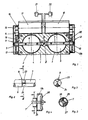
- FIG. 1 shows a throttle valve connector 1, which has two parallel intake ducts 2, 3, each with a throttle valve 4, 5.
- the two throttle valves 4, 5 are each arranged on a horizontally arranged actuating shaft 6, 7, both of which are in alignment with one another and are coupled to one another by a driver connection 8 having play.
- Both actuating shafts 6, 7 are led out laterally from the throttle valve connector 1 and are each connected to a gear 11, 12 there by means of a slip clutch 9, 10.
- Each gear 11, 12 consists of three intermeshing gear wheels 13, 14, 15, the gear wheel 15 on an output shaft 16 of a servomotor 17 designed as a stepping motor is rotatably arranged.
- a second servomotor 18, also designed as a stepper motor, is arranged in mirror image of the first servomotor 17 on the upper side of the throttle valve connector 1 and drives the actuating shaft 7 in the same way via the gear 12.
- each actuating shaft 6, 7 is assigned a safety contact 19, 20 which, when the actuating motor 17, 18 is energized but the actuating shaft 6, 7 is not rotating, controls a warning device 21, 22.
- FIGS. 2 and 3 show the design of the driver connection 8 more precisely.
- the mutually facing end faces of the two adjusting shafts 6, 7 each have a sector-shaped projection 23, 24. These projections each have an angle of 90 degrees, so that an angle of 90 degrees also remains between them, as shown in FIG. If the throttle valves 4, 5 move synchronously, the projections 23, 24 lie opposite one another. If, for example, the throttle valve 4 is at a standstill as a result of a defect, the right throttle valve 5 can pivot freely up to 90 degrees. In such a case, the normal operation of the right throttle valve 5 would in no way be hindered by the failed left throttle valve 4.
- the right throttle valve 5 can be pivoted motor-wise through an angle of 90 degrees, the driver connection 8 taking the left throttle valve 4 with it after a pivoting angle of 90 degrees, so that it can be closed. This results in a relative movement in the slip clutch 9. After the load adjustment device has been repaired, this rotation in the slip clutch must of course be reset.
- FIG. 4 and 5 illustrate the design of the slip clutch 12. It can be seen that the gear 13b is frictionally connected to the actuating shaft 7 via a plate spring 28. A pin 25 extends radially through the adjusting shaft 7, against which the gear 13b can turn with the stop segments 26, 27 shown in FIG. 5, so that the adjusting shaft 7 is carried in a form-fitting manner. If the gear 13b rotates counterclockwise and the actuating shaft 7 is sufficiently stiff, then there is a relative movement between the gear 13b and the actuating shaft 7 until the other side of the stop segments 26, 27 comes against the pin 25 and then the actuating shaft 7 carries along. Since both gearboxes 11, 12 have such a slip clutch 9, 10, if a gearbox 11, 12 is blocked via the other gearbox, the throttle valve, which is no longer functional, can be moved into the closed position due to a slipping clutch.
- actuating shafts 6, 7 do not run in alignment, but parallel to one another.
- Each control shaft 6, 7 is driven directly by a servomotor 17, 18.
- the driver connection 8 is in turn designed so that both throttle valves 4, 5 can pivot independently of each other up to a maximum of about 90 degrees. In the event of a further pivoting, the other throttle valve 4 or 5 is taken along by the driver connection 8.
- the structure of the driver connection 8 can be seen in FIG. 7. It has an actuating segment 29, 30 on each actuating shaft 6, 7, each with an arc-shaped elongated hole 31, 32.
- the ends of a coupling rod 33 each engage in one of the elongated holes 31, 32.
- closed position of the throttle valves 4 and 5 the coupling rod 33 each against a left boundary of the respective elongated hole 31, 32.
- the right throttle valve 5 can no longer be actuated by the associated servomotor 18, then the right throttle valve 5 is carried along by the coupling rod 33 after pivoting the left throttle valve 4 by 90 degrees, so that it can be moved into the closed position.
Landscapes
- Engineering & Computer Science (AREA)
- Chemical & Material Sciences (AREA)
- Combustion & Propulsion (AREA)
- Mechanical Engineering (AREA)
- General Engineering & Computer Science (AREA)
- Control Of Throttle Valves Provided In The Intake System Or In The Exhaust System (AREA)
Applications Claiming Priority (2)
| Application Number | Priority Date | Filing Date | Title |
|---|---|---|---|
| DE3909570 | 1989-03-23 | ||
| DE3909570A DE3909570A1 (de) | 1989-03-23 | 1989-03-23 | Lastverstelleinrichtung |
Publications (3)
| Publication Number | Publication Date |
|---|---|
| EP0388505A2 true EP0388505A2 (fr) | 1990-09-26 |
| EP0388505A3 EP0388505A3 (en) | 1990-10-24 |
| EP0388505B1 EP0388505B1 (fr) | 1993-11-03 |
Family
ID=6377045
Family Applications (1)
| Application Number | Title | Priority Date | Filing Date |
|---|---|---|---|
| EP89110065A Expired - Lifetime EP0388505B1 (fr) | 1989-03-23 | 1989-06-03 | Dispositif de réglage de charge |
Country Status (4)
| Country | Link |
|---|---|
| US (1) | US5036816A (fr) |
| EP (1) | EP0388505B1 (fr) |
| JP (1) | JPH02259247A (fr) |
| DE (2) | DE3909570A1 (fr) |
Cited By (2)
| Publication number | Priority date | Publication date | Assignee | Title |
|---|---|---|---|---|
| FR2900455A1 (fr) * | 2006-04-26 | 2007-11-02 | Valeo Sys Controle Moteur Sas | Vanne a deux papillons actionnes par un moteur commun |
| EP1712762A4 (fr) * | 2003-11-12 | 2011-06-22 | Husqvarna Zenoah Co Ltd | Mecanisme de conduction et de couplage |
Families Citing this family (39)
| Publication number | Priority date | Publication date | Assignee | Title |
|---|---|---|---|---|
| GB9102121D0 (en) * | 1991-01-31 | 1991-03-13 | Jaguar Cars | Air induction system for an internal combustion engine |
| JP2593364B2 (ja) * | 1991-03-01 | 1997-03-26 | 本田技研工業株式会社 | 多気筒内燃機関の吸気装置 |
| DE4126369A1 (de) * | 1991-08-09 | 1993-02-11 | Vdo Schindling | Lastverstelleinrichtung |
| DE4126367A1 (de) * | 1991-08-09 | 1993-02-11 | Vdo Schindling | Lastverstelleinrichtung zur steuerung der leistung einer brennkraftmaschine unter verwendung zweier drosselklappen |
| US5325829A (en) * | 1992-09-25 | 1994-07-05 | Schmelzer Corporation | Intake manifold air inlet control actuator |
| US5419293A (en) * | 1993-02-01 | 1995-05-30 | Fuji Jukogyo Kabushiki Kaisha | Fail-safe system of an automatic driving system for a motor vehicle |
| GB9406769D0 (en) * | 1994-04-06 | 1994-05-25 | Btr Plc | Valve system |
| DE69627401T3 (de) * | 1995-01-17 | 2014-01-30 | Hitachi, Ltd. | Luftströmungssteuervorrichtung |
| JPH08303216A (ja) * | 1995-05-08 | 1996-11-19 | Fuji Oozx Inc | 内燃機関用タペットの製造方法 |
| DE19524068A1 (de) * | 1995-07-01 | 1997-01-02 | Behr Gmbh & Co | Aktuatoranordnung und diese verwendende Vorrichtung |
| US5647399A (en) * | 1995-08-03 | 1997-07-15 | Valeo Climate Control Inc. | Flow control device |
| KR19980019820A (ko) * | 1996-09-03 | 1998-06-25 | 김영귀 | 2중가변 트로틀밸브 |
| EP0911506A3 (fr) * | 1997-10-21 | 2000-12-27 | Hitachi, Ltd. | Dispositif de papillon commandé électroniquement pour moteur à combustion |
| JP3818562B2 (ja) * | 1999-02-01 | 2006-09-06 | TI Walbro Japan株式会社 | 層状掃気用気化器 |
| JP2000282874A (ja) | 1999-03-29 | 2000-10-10 | Nippon Walbro:Kk | 絞り弁と空気弁を備えた2行程内燃機関用気化器 |
| DE19918777A1 (de) * | 1999-04-24 | 2000-10-26 | Mann & Hummel Filter | Schaltklappenverband aus montagegespritzten Schaltklappen oder Klappenmodulen |
| DE19951582A1 (de) * | 1999-10-27 | 2001-05-03 | Bosch Gmbh Robert | Verfahren und Vorrichtung zur Synchronisation von wenigstens zwei Leistungsstellelementen einer Brennkraftmaschine |
| US6173939B1 (en) * | 1999-11-10 | 2001-01-16 | Ford Global Technologies, Inc. | Electronic throttle control system with two-spring failsafe mechanism |
| US6591794B2 (en) | 2000-10-24 | 2003-07-15 | Zama Japan | Air-fuel ratio control system for a stratified scavenging two-cycle engine |
| DE10126063B4 (de) * | 2001-05-28 | 2004-07-15 | Montaplast Gmbh | Klappenvorrichtung |
| US7066142B2 (en) * | 2002-09-11 | 2006-06-27 | Mikuni Corporation | Multiple throttle apparatus |
| US7156074B2 (en) * | 2002-10-11 | 2007-01-02 | Mikuni Corporation | Throttle device |
| JP2004176634A (ja) * | 2002-11-27 | 2004-06-24 | Walbro Japan Inc | 層状掃気用気化器 |
| DE10345311B4 (de) * | 2003-09-30 | 2015-07-30 | Robert Bosch Gmbh | Verfahren zum Betreiben einer Brennkraftmaschine, sowie Computerprogramm, elektrisches Speichermedium, Steuer- und/oder Regeleinrichtung und Brennkraftmaschine |
| US6860464B1 (en) | 2004-01-29 | 2005-03-01 | Honeywell International Inc. | Electromechanical/pneumatic rocket engine valve actuator |
| SE526804C2 (sv) * | 2004-03-26 | 2005-11-08 | Stt Emtec Ab | Ventilanordning |
| US7104253B1 (en) | 2005-03-30 | 2006-09-12 | Walbro Engine Management, L.L.C. | Stratified scavenging carburetor |
| US7543563B2 (en) * | 2007-03-23 | 2009-06-09 | Honda Motor Co., Ltd. | High flow dual throttle body for small displacement engines |
| US8056542B2 (en) * | 2008-05-12 | 2011-11-15 | Thomas Engine Company, Llc | Intake system for a barrel internal combustion engine |
| US7735467B2 (en) * | 2008-10-21 | 2010-06-15 | Gm Global Technology Operations, Inc. | Engine with progressive dual bore electronic throttle body |
| US8453998B2 (en) * | 2010-08-17 | 2013-06-04 | Walbro Engine Management, L.L.C. | Air scavenging carburetor |
| DE102010044160A1 (de) * | 2010-11-19 | 2012-05-24 | Mahle International Gmbh | Ventileinrichtung und Brennkraftmaschine |
| US20150240727A1 (en) * | 2012-10-11 | 2015-08-27 | Norgren Gt Development Corporation | Inlet throttle |
| KR101534746B1 (ko) * | 2014-05-21 | 2015-07-07 | 현대자동차 주식회사 | 차량의 연료전지 복합 밸브 |
| DE102015210157B4 (de) * | 2014-06-04 | 2021-12-23 | Schaeffler Technologies AG & Co. KG | Mehrkammer-Drehventilmodul für Wärme-Management |
| JP6424117B2 (ja) * | 2015-03-18 | 2018-11-14 | 株式会社ケーヒン | 吸気制御装置 |
| JP6466310B2 (ja) * | 2015-12-08 | 2019-02-06 | 株式会社ニフコ | クリップ |
| US11118688B2 (en) * | 2019-06-05 | 2021-09-14 | Caterpillar Inc. | Throttle with integrated fluid shutoff trigger mechanism |
| US11022079B1 (en) * | 2020-02-21 | 2021-06-01 | Deere & Company | Dual element engine gas valve |
Family Cites Families (16)
| Publication number | Priority date | Publication date | Assignee | Title |
|---|---|---|---|---|
| DE1172089B (de) * | 1960-09-14 | 1964-06-11 | Maschf Augsburg Nuernberg Ag | Klappenventil |
| DE2204192C3 (de) * | 1972-01-29 | 1979-03-22 | Robert Bosch Gmbh, 7000 Stuttgart | Vorrichtung zur Verbesserung der Abgase einer Vergaser-Brennkraftmaschine |
| US3934851A (en) * | 1973-12-12 | 1976-01-27 | Kieley & Mueller, Inc. | Butterfly valve having a split vane |
| US3897524A (en) * | 1974-01-04 | 1975-07-29 | Ford Motor Co | Carburetor secondary throttle shaft construction |
| DE2637122A1 (de) * | 1976-08-18 | 1978-02-23 | Bosch Gmbh Robert | Stellglied zur beeinflussung einer regelstrecke |
| US4246115A (en) * | 1978-08-28 | 1981-01-20 | Cummins Engine Company, Inc. | Multi-valve interlock apparatus |
| DE3108090A1 (de) * | 1981-03-04 | 1982-09-16 | Pierburg Gmbh & Co Kg, 4040 Neuss | Verfahren und vorrichtung zum ansteuern der vordrosseln von registervergasern |
| JPS5872615A (ja) * | 1981-10-26 | 1983-04-30 | Hino Motors Ltd | バイパス弁の作動装置 |
| JPH0663460B2 (ja) * | 1986-06-02 | 1994-08-22 | 株式会社日立製作所 | 電動機駆動型絞弁用の絞弁組立体 |
| JPS6385234A (ja) * | 1986-09-29 | 1988-04-15 | Mitsubishi Electric Corp | スロツトルバルブ制御装置 |
| JPH086611B2 (ja) * | 1987-03-26 | 1996-01-29 | 日産自動車株式会社 | 車載エンジン制御装置 |
| US4809656A (en) * | 1987-04-14 | 1989-03-07 | Nippon Cable System Inc. | Actuator for automatic cruising system |
| US4827884A (en) * | 1987-10-02 | 1989-05-09 | Bendix Electronics Limited | Throttle assembly |
| JPH01142224A (ja) * | 1987-11-27 | 1989-06-05 | Mitsubishi Electric Corp | 機関のスロットルバルブ制御装置 |
| US4850319A (en) * | 1988-02-18 | 1989-07-25 | Siemens-Bendix Automotive Electronics L.P. | Electronic throttle actuator |
| US4846225A (en) * | 1988-09-19 | 1989-07-11 | Keystone International, Inc. | Transmission assembly for use with double block and bleed system |
-
1989
- 1989-03-23 DE DE3909570A patent/DE3909570A1/de not_active Withdrawn
- 1989-06-03 DE DE89110065T patent/DE58906114D1/de not_active Expired - Fee Related
- 1989-06-03 EP EP89110065A patent/EP0388505B1/fr not_active Expired - Lifetime
- 1989-09-22 JP JP1245398A patent/JPH02259247A/ja active Pending
-
1990
- 1990-02-23 US US07/485,210 patent/US5036816A/en not_active Expired - Fee Related
Cited By (9)
| Publication number | Priority date | Publication date | Assignee | Title |
|---|---|---|---|---|
| EP1712762A4 (fr) * | 2003-11-12 | 2011-06-22 | Husqvarna Zenoah Co Ltd | Mecanisme de conduction et de couplage |
| FR2900455A1 (fr) * | 2006-04-26 | 2007-11-02 | Valeo Sys Controle Moteur Sas | Vanne a deux papillons actionnes par un moteur commun |
| WO2007125204A1 (fr) * | 2006-04-26 | 2007-11-08 | Valeo Systemes De Controle Moteur | Dispositif d'admission d'air d'un moteur thermique ayant un circuit principal refroidi et un circuit derive pourvu de moyens de chauffage |
| WO2007125205A1 (fr) * | 2006-04-26 | 2007-11-08 | Valeo Systemes De Controle Moteur | Vanne a deux papillons actionnes par un moteur commun |
| WO2007129172A3 (fr) * | 2006-04-26 | 2008-12-04 | Valeo Sys Controle Moteur Sas | Soupape à deux obturateurs |
| US7992589B2 (en) | 2006-04-26 | 2011-08-09 | Valeo Systemes De Controle Moteur | Dual butterfly valve driven by a common drive motor |
| US8074628B2 (en) | 2006-04-26 | 2011-12-13 | Valeo Systemes De Controle Moteur | Air intake device for a heat engine with a cooled main circulation system and a bypass system equipped with a heating mechanism |
| CN101432509B (zh) * | 2006-04-26 | 2012-06-06 | 法雷奥电机控制系统公司 | 用于热机的进气装置的阀 |
| US8684033B2 (en) | 2006-04-26 | 2014-04-01 | Valeo Systemes De Controle Moteur | Two-shutter valve |
Also Published As
| Publication number | Publication date |
|---|---|
| DE58906114D1 (de) | 1993-12-09 |
| JPH02259247A (ja) | 1990-10-22 |
| EP0388505A3 (en) | 1990-10-24 |
| DE3909570A1 (de) | 1990-09-27 |
| US5036816A (en) | 1991-08-06 |
| EP0388505B1 (fr) | 1993-11-03 |
Similar Documents
| Publication | Publication Date | Title |
|---|---|---|
| EP0388505B1 (fr) | Dispositif de réglage de charge | |
| EP1334297B1 (fr) | Dispositif de reglage pour boite de vitesses ajustable | |
| DE68907405T2 (de) | Elektronische drosselklappenstelleinrichtung. | |
| EP0413081A1 (fr) | Dispositif de réglage de charge | |
| DE3504708A1 (de) | Verschleissnachstellvorrichtung fuer die betaetigung einer kupplungsvorrichtung | |
| DE3927043A1 (de) | Lastverstelleinrichtung | |
| DE2825355A1 (de) | Einrichtung zur elektromotorischen zentralverriegelung von kraftfahrzeugen | |
| EP0427097B1 (fr) | Soupape d'étranglement pour moteur à combustion interne | |
| DE4027269A1 (de) | Drosselklappenstutzen | |
| DE3317191A1 (de) | Ventilaktuator | |
| DE3711779A1 (de) | Drosselklappe | |
| EP0402521A1 (fr) | Dispositif de réglage de charge | |
| DE3813047A1 (de) | Verstelleinrichtung fuer die drosselklappe einer gemischbildungseinrichtung fuer brennkraftmaschinen | |
| DE3735901C2 (de) | Drosselklappenstellvorrichtung | |
| DE19736521A1 (de) | Lastverstellvorrichtung | |
| EP1903198B1 (fr) | Dispositif destiné à l'actionnement d'une soupape à clapets dans une installation de dégazage | |
| EP0810359A2 (fr) | Dispositif de commande de charge | |
| EP0421047B1 (fr) | Dispositif de réglage de charge | |
| DE2700928A1 (de) | Stellantrieb fuer luft- und drosselklappen, mischhaehne u.dgl. in heizungs- und lueftungsanlagen | |
| DE102021104727A1 (de) | Pedal für ein Fahrzeug | |
| DE4129928A1 (de) | Stellantrieb | |
| DE102024113396B4 (de) | Getriebe mit nichtlinearer Kennlinie | |
| DE69314199T2 (de) | Drosselklappenstelleinrichtung | |
| DE10143323A1 (de) | Elektrischer Stellantrieb an einem Getriebe | |
| DE19519836C5 (de) | Lastverstelleinrichtung |
Legal Events
| Date | Code | Title | Description |
|---|---|---|---|
| PUAI | Public reference made under article 153(3) epc to a published international application that has entered the european phase |
Free format text: ORIGINAL CODE: 0009012 |
|
| PUAL | Search report despatched |
Free format text: ORIGINAL CODE: 0009013 |
|
| AK | Designated contracting states |
Kind code of ref document: A2 Designated state(s): DE FR GB IT SE |
|
| AK | Designated contracting states |
Kind code of ref document: A3 Designated state(s): DE FR GB IT SE |
|
| 17P | Request for examination filed |
Effective date: 19900911 |
|
| 17Q | First examination report despatched |
Effective date: 19920306 |
|
| GRAA | (expected) grant |
Free format text: ORIGINAL CODE: 0009210 |
|
| AK | Designated contracting states |
Kind code of ref document: B1 Designated state(s): DE FR GB IT SE |
|
| ET | Fr: translation filed | ||
| REF | Corresponds to: |
Ref document number: 58906114 Country of ref document: DE Date of ref document: 19931209 |
|
| GBT | Gb: translation of ep patent filed (gb section 77(6)(a)/1977) |
Effective date: 19931111 |
|
| ITF | It: translation for a ep patent filed | ||
| PGFP | Annual fee paid to national office [announced via postgrant information from national office to epo] |
Ref country code: GB Payment date: 19940516 Year of fee payment: 6 |
|
| PGFP | Annual fee paid to national office [announced via postgrant information from national office to epo] |
Ref country code: FR Payment date: 19940519 Year of fee payment: 6 |
|
| PGFP | Annual fee paid to national office [announced via postgrant information from national office to epo] |
Ref country code: SE Payment date: 19940524 Year of fee payment: 6 |
|
| PLBE | No opposition filed within time limit |
Free format text: ORIGINAL CODE: 0009261 |
|
| STAA | Information on the status of an ep patent application or granted ep patent |
Free format text: STATUS: NO OPPOSITION FILED WITHIN TIME LIMIT |
|
| 26N | No opposition filed | ||
| EAL | Se: european patent in force in sweden |
Ref document number: 89110065.3 |
|
| PG25 | Lapsed in a contracting state [announced via postgrant information from national office to epo] |
Ref country code: GB Effective date: 19950603 |
|
| PG25 | Lapsed in a contracting state [announced via postgrant information from national office to epo] |
Ref country code: SE Effective date: 19950604 |
|
| GBPC | Gb: european patent ceased through non-payment of renewal fee |
Effective date: 19950603 |
|
| PG25 | Lapsed in a contracting state [announced via postgrant information from national office to epo] |
Ref country code: FR Effective date: 19960229 |
|
| EUG | Se: european patent has lapsed |
Ref document number: 89110065.3 |
|
| REG | Reference to a national code |
Ref country code: FR Ref legal event code: ST |
|
| PGFP | Annual fee paid to national office [announced via postgrant information from national office to epo] |
Ref country code: DE Payment date: 19970516 Year of fee payment: 9 |
|
| PG25 | Lapsed in a contracting state [announced via postgrant information from national office to epo] |
Ref country code: DE Free format text: LAPSE BECAUSE OF NON-PAYMENT OF DUE FEES Effective date: 19990401 |
|
| PG25 | Lapsed in a contracting state [announced via postgrant information from national office to epo] |
Ref country code: IT Free format text: LAPSE BECAUSE OF NON-PAYMENT OF DUE FEES;WARNING: LAPSES OF ITALIAN PATENTS WITH EFFECTIVE DATE BEFORE 2007 MAY HAVE OCCURRED AT ANY TIME BEFORE 2007. THE CORRECT EFFECTIVE DATE MAY BE DIFFERENT FROM THE ONE RECORDED. Effective date: 20050603 |