EP0389214A2 - Poutre composite, connecteur et construction - Google Patents
Poutre composite, connecteur et construction Download PDFInfo
- Publication number
- EP0389214A2 EP0389214A2 EP90302914A EP90302914A EP0389214A2 EP 0389214 A2 EP0389214 A2 EP 0389214A2 EP 90302914 A EP90302914 A EP 90302914A EP 90302914 A EP90302914 A EP 90302914A EP 0389214 A2 EP0389214 A2 EP 0389214A2
- Authority
- EP
- European Patent Office
- Prior art keywords
- connector
- units
- members
- further characterised
- stringers
- Prior art date
- Legal status (The legal status is an assumption and is not a legal conclusion. Google has not performed a legal analysis and makes no representation as to the accuracy of the status listed.)
- Withdrawn
Links
- 239000002131 composite material Substances 0.000 title claims abstract description 8
- 238000010276 construction Methods 0.000 title claims description 12
- 230000015572 biosynthetic process Effects 0.000 claims description 6
- 238000005755 formation reaction Methods 0.000 claims description 6
- 239000000853 adhesive Substances 0.000 description 3
- 230000001070 adhesive effect Effects 0.000 description 3
- 125000006850 spacer group Chemical group 0.000 description 3
- 229910045601 alloy Inorganic materials 0.000 description 2
- 239000000956 alloy Substances 0.000 description 2
- 229910052782 aluminium Inorganic materials 0.000 description 2
- 239000004411 aluminium Substances 0.000 description 2
- XAGFODPZIPBFFR-UHFFFAOYSA-N aluminium Chemical compound [Al] XAGFODPZIPBFFR-UHFFFAOYSA-N 0.000 description 2
- 239000000463 material Substances 0.000 description 2
- 230000013011 mating Effects 0.000 description 2
- 229910000838 Al alloy Inorganic materials 0.000 description 1
- 229910000831 Steel Inorganic materials 0.000 description 1
- 230000006835 compression Effects 0.000 description 1
- 238000007906 compression Methods 0.000 description 1
- 238000004512 die casting Methods 0.000 description 1
- 238000007599 discharging Methods 0.000 description 1
- 229920006351 engineering plastic Polymers 0.000 description 1
- 230000002349 favourable effect Effects 0.000 description 1
- 239000011521 glass Substances 0.000 description 1
- 238000002347 injection Methods 0.000 description 1
- 239000007924 injection Substances 0.000 description 1
- 238000001746 injection moulding Methods 0.000 description 1
- 239000010959 steel Substances 0.000 description 1
- 238000005728 strengthening Methods 0.000 description 1
Images


Classifications
-
- E—FIXED CONSTRUCTIONS
- E04—BUILDING
- E04C—STRUCTURAL ELEMENTS; BUILDING MATERIALS
- E04C3/00—Structural elongated elements designed for load-supporting
- E04C3/02—Joists; Girders, trusses, or trusslike structures, e.g. prefabricated; Lintels; Transoms; Braces
- E04C3/29—Joists; Girders, trusses, or trusslike structures, e.g. prefabricated; Lintels; Transoms; Braces built-up from parts of different material, i.e. composite structures
- E04C3/291—Joists; Girders, trusses, or trusslike structures, e.g. prefabricated; Lintels; Transoms; Braces built-up from parts of different material, i.e. composite structures with apertured web
-
- E—FIXED CONSTRUCTIONS
- E04—BUILDING
- E04H—BUILDINGS OR LIKE STRUCTURES FOR PARTICULAR PURPOSES; SWIMMING OR SPLASH BATHS OR POOLS; MASTS; FENCING; TENTS OR CANOPIES, IN GENERAL
- E04H12/00—Towers; Masts or poles; Chimney stacks; Water-towers; Methods of erecting such structures
- E04H12/02—Structures made of specified materials
- E04H12/08—Structures made of specified materials of metal
-
- E—FIXED CONSTRUCTIONS
- E04—BUILDING
- E04B—GENERAL BUILDING CONSTRUCTIONS; WALLS, e.g. PARTITIONS; ROOFS; FLOORS; CEILINGS; INSULATION OR OTHER PROTECTION OF BUILDINGS
- E04B1/00—Constructions in general; Structures which are not restricted either to walls, e.g. partitions, or floors or ceilings or roofs
- E04B1/18—Structures comprising elongated load-supporting parts, e.g. columns, girders, skeletons
- E04B1/24—Structures comprising elongated load-supporting parts, e.g. columns, girders, skeletons the supporting parts consisting of metal
- E04B1/2403—Connection details of the elongated load-supporting parts
- E04B2001/2406—Connection nodes
-
- E—FIXED CONSTRUCTIONS
- E04—BUILDING
- E04B—GENERAL BUILDING CONSTRUCTIONS; WALLS, e.g. PARTITIONS; ROOFS; FLOORS; CEILINGS; INSULATION OR OTHER PROTECTION OF BUILDINGS
- E04B1/00—Constructions in general; Structures which are not restricted either to walls, e.g. partitions, or floors or ceilings or roofs
- E04B1/18—Structures comprising elongated load-supporting parts, e.g. columns, girders, skeletons
- E04B1/24—Structures comprising elongated load-supporting parts, e.g. columns, girders, skeletons the supporting parts consisting of metal
- E04B2001/2466—Details of the elongated load-supporting parts
- E04B2001/2472—Elongated load-supporting part formed from a number of parallel profiles
Definitions
- This invention relates to a composite beam, pillar or truss, to a connector therefor, and to a construction incorporating such beams.
- the invention is particularly concerned with the construction of prefabricated large-scale temporary buildings such as exhibition halls, but also with structures which are not themselves buildings , for example the construction of lighting rigs.
- a composite beam, pillar or truss will hereinafter be called a "beam" for convenience. It is desirable to be able to provide structures such as those listed in a variety of shapes and sizes by the use of modular construction for the beams and pillars so that only a small number of standard types of part are needed in stock.
- a composite beam comprising a plurality of modular units, each unit having identical corner formations, the units being disposed end to end to define the length of a beam;
- the units may be of polygonal outline and are preferably square.
- Each unit may comprise a space-frame of pyramidal form comprising a plurality of struts, equi-spaced about an apertured core and intersecting a polygonal end frame.
- each unit may be conical having an apertured core and a polygonal end frame.
- the apertured core may have laterally facing and longitudinally facing apertures to permit passage of services into and through the beam.
- each structure may be of 3 winged, circular or triangular cross-section for rigidity,
- Alternate units may be inverted when being disposed end to end.
- the keyed engagement may be made between grooves of the stringers and projections or ribs of the units. Spacers may be provided between adjacent such projections or ribs to fill the grooves along their entire length.
- the end caps may be arranged to bear on the units to exert a compressive pre-tension on the beam.
- Tie rods passed through the stringers may be connected to the end caps to exert said compressive pre-tension, or alternatively threaded inserts may be used to exert pre-tension.
- the stringers may be cut to length slightly shorter than the plurality of units to which they are keyed, so that attachment of the end caps may compress the units slightly in length.
- Adhesive may be introduced into the grooves after final assembly to lock the beam together.
- a connector for beams comprising a number of polygonal face members, each face member having connection means capable of connection to a respective beam, the face members being adapted to be connected together into a three-dimensional body having a plurality of corners at each of which three members meet, the connector comprising a corresponding plurality of internal corner members and a corresponding plurality of external corner members adapted to be secured respectively internally and externally of the corners to clamp three face members together at each of the corners.
- the polygonal face members are generally square and the three-dimensional body is a cube.
- Each cube member may have a central aperture whereby services such as cables and pipework can be passed through the connector in any direction.
- Each face member may have a screw thread adapted to mate with a thread provided on a beam.
- the invention provides a construction comprising a plurality of opposite beams as set out above, connected together by means of one or more connectors as set out above.
- the construction may comprise a building.
- the construction may include a rainwater drainage assembly for a roof, the assembly comprising beams secured together by connectors as set out above, the assembly further comprising a rainwater collector on said roof, a drain pipe extending from said collector to one of said connectors, and a vertical drain extending from said connector to discharge.
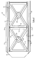
- a beam pillar or truss 10 is made up of a plurality of units 11, a plurality of elongate stringers 12 and a pair of end caps 13, only one of which is shown in Figures 1 and 2.
- Each unit 11 comprises a pyramidal space-frame having a frame 14 of square outline, a central apertured core 15 and four struts 16 connecting the frame 14 and the core 15.
- the arrangement is best seen in Figures 2 and 3.
- the outline of the unit is square in the example shown, it could be of other polygonal outline, such as triangular, or could be conical.
- Each pyramidal unit 11 is assembled next to another in an inverted condition as seen in Figure 2.
- the units 11 have corner formations 17, best seen in Figure 2, which comprise ribs or projections which are slidable in and keyed into elongate grooves 18 of the stringers 12.
- Spacers 19 are inserted between the corner formations of adjacent units to fill the grooves from end to end of the stringers.
- the stringers 12 are cut to the desired length of the beam 10 and assembled with the appropriate number of units 11, which are arranged to project slightly at the ends of the stringers 12. End caps 13 are then attached to the stringers and arranged to bear on the units to exert a compressive pre-tension, to maintain the integrity of the beam in use.
- FIG. 1 The arrangement of the end caps is best illustrated in Figure 1, where it will be seen that threaded bolts 20 are passed through the end caps into the stringers. These bolts 20 engage within hollow tie rods, one of which is shown at 21 projecting from the stringer. Each stringer receives a tie rod passing throughout its length and the respective end caps are attached by the bolts 20 at each end of the beam. Tightening of the bolts 20 exerts the required pre-tension on the beam. Alternatively, threaded inserts may be used at the ends of the beam for pre-tensioning.
- Pre-tensioning assists in strengthening the composite beam so that it is strong in tension, compression and against flexure. Strength is also ensured by the triangulation within the beam due to the pyramidal shape of the units.
- Each strut 16 has good stiffness because of the use of a favourable cross-section.
- the struts are tri-winged but they could alternatively be circular or triangular in cross-section.
- Conical units may be preferred in large-scale application to further increase torsional stiffness.
- the units 11 may be made of a suitable glass-filled engineering plastics material by injection moulding.
- the spacers 19 are of the same material.
- the stringers 12 are made in extruded aluminium or alloy and cut to length.
- the tie rods 21 are preferably of steel to give the desired tensile strength for compressive pre-tensioning of the beam.
- the end caps 13 are die-cast in aluminium alloy.
- each unit is arranged to permit passage of services such as cables and pipeworks into and through the beam.
- the core has both a longitudinally facing aperture 22 and laterally facing part apertures 23. These apertures may also provide means for drainage of rainwater falling on a roof supported by a building structure made up of beams as will later be described.
- connection means may be used as beams, pillars or trusses, and may be assembled together or to other structures by connection means associated with the end caps.
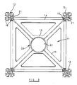
- a preferred form of connection means is shown in Figures 4 to 6 of the drawings.
- Figure 7 shows an assembly of beam and connection means.
- a three-dimensional connector 110 for beams is made up of a number of face members 111, each identical.
- the connector shown is a cube, made up of six square face members, but other three-dimensional forms could be selected, with appropriately shaped polygonal faces, for example a triangular pyramid having equilateral triangular face members.
- the face members each have corner rebates 112. Corner members and fasteners are provided to secure the face members 111 together to form the cube-shaped connector 110. These consist of eight internal corner members 113 and eight external corner members 114. At each corner, three of the face members meet and the internal corner member overlaps the corner rebates 112 of these face members.
- the external corner member is presented from outside and secured in place by means of a fastener 115 which has a thread mating with an internally threaded bush 116 of the internal corner member 113. Adhesive may be used between the mating surfaces.
- Figure 6 shows the inner and outer corner members 113 and 114 in section, showing the way in which the corner rebates 112 locate the inner and outer corner members 113 and 114, which can then clamp the three face members together .
- Each face member has an aperture 117, surrounded by an attachment collar 118 which has tapered fins 119.
- the collar has an internal screw thread 120 of shallow three-start from for the connection of beams 10 to the connector.
- connection could alternatively be a bayonet-type connection.
- Figure 7 shows the connection of the beam 10.
- the end caps 13 have a threaded connection with the three-start threads 120 of the connector.
- the beam 10, including its end cap 13, has a central through opening. Additionally, lateral openings are provided in the units 11. Through these openings, services such as cables and pipework can be passed into the connector 110, and from there, into other connected beams in any chosen direction.
- a pipe 125 is shown entering the connector 110 from the beam 10.
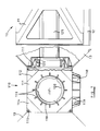
- Figure 8 shows this feature used in a rainwater drainage system for a roof supported by beams and connectors.
- the pipe 125 can be seen, entering and discharging into the connector 110.
- the latter is supported by a lower beam or pillar 126, through which a rainwater downpipe 127 discharges.
- the pipe 125 is fed from a collector 128 on the roof through a lateral opening 129 communicating with the pipe 125 within the beam.
- the connector is made in aluminium or a suitable alloy by die-casting. Its construction requires only a small number of parts, namely the face members, internal and external corner members, which can be assembled as described to produce a connector.
- the screw connection for attachment of the beams makes for easy assembly of the building structure with consistent accuracy of positioning of the beams. Because of the aperture in each face member, drainage systems and services such as cables can be fed through the beams and connectors in a secure and tidy manner, not obstructing the interior of the building.
Landscapes
- Engineering & Computer Science (AREA)
- Architecture (AREA)
- Chemical & Material Sciences (AREA)
- Civil Engineering (AREA)
- Structural Engineering (AREA)
- Life Sciences & Earth Sciences (AREA)
- Materials Engineering (AREA)
- Wood Science & Technology (AREA)
- Composite Materials (AREA)
- Joining Of Building Structures In Genera (AREA)
- Rod-Shaped Construction Members (AREA)
Applications Claiming Priority (4)
| Application Number | Priority Date | Filing Date | Title |
|---|---|---|---|
| GB8906459 | 1989-03-21 | ||
| GB898906458A GB8906458D0 (en) | 1989-03-21 | 1989-03-21 | Composite beam |
| GB898906459A GB8906459D0 (en) | 1989-03-21 | 1989-03-21 | Connector for beams |
| GB8906458 | 1989-03-21 |
Publications (2)
| Publication Number | Publication Date |
|---|---|
| EP0389214A2 true EP0389214A2 (fr) | 1990-09-26 |
| EP0389214A3 EP0389214A3 (fr) | 1990-11-28 |
Family
ID=26295119
Family Applications (1)
| Application Number | Title | Priority Date | Filing Date |
|---|---|---|---|
| EP19900302914 Withdrawn EP0389214A3 (fr) | 1989-03-21 | 1990-03-19 | Poutre composite, connecteur et construction |
Country Status (2)
| Country | Link |
|---|---|
| US (1) | US5119613A (fr) |
| EP (1) | EP0389214A3 (fr) |
Cited By (11)
| Publication number | Priority date | Publication date | Assignee | Title |
|---|---|---|---|---|
| EP0750362A1 (fr) * | 1995-06-23 | 1996-12-27 | Paul Lingen | Mât d'échafaudage |
| DE19714996A1 (de) * | 1997-04-10 | 1998-10-29 | Octanorm Vertriebs Gmbh | Gitterträger zur Herstellung mobiler Bauten |
| WO2001036750A1 (fr) * | 1999-11-15 | 2001-05-25 | Juralco A/S | Mat |
| WO2004088066A1 (fr) * | 2003-04-04 | 2004-10-14 | Tower Solutions Inc. | Structure de tour modulaire |
| ES2328201A1 (es) * | 2007-03-30 | 2009-11-10 | Jaime Alberto Sarmiento Ocampo | Autoconstruccion industrializada modular y climatizada por autoventilacion natural. |
| CN103967317A (zh) * | 2014-05-26 | 2014-08-06 | 国家电网公司 | 一种输电线路抢修塔塔身 |
| CN104074388A (zh) * | 2013-03-28 | 2014-10-01 | 国家电网公司 | 一种组合式高压线路抢修塔用单元体 |
| CN104863407A (zh) * | 2015-05-29 | 2015-08-26 | 中国电力科学研究院 | 一种输电线路的抢修塔 |
| ITUB20169951A1 (it) * | 2016-01-13 | 2017-07-13 | Federico Lestini | Struttura di edificio modulare |
| JP2019502044A (ja) * | 2016-01-13 | 2019-01-24 | エンメアッラエンネ エス.アール.エル. | 一体化プラントを有するモジュール式建築構造 |
| CN113073890A (zh) * | 2021-03-18 | 2021-07-06 | 和勤通信技术有限公司 | 拉线塔 |
Families Citing this family (10)
| Publication number | Priority date | Publication date | Assignee | Title |
|---|---|---|---|---|
| JPH0967869A (ja) * | 1995-08-31 | 1997-03-11 | Nisso Ind Co Ltd | ユニット建物の継手金具 |
| US6032430A (en) * | 1996-10-24 | 2000-03-07 | Soukup; Eduardo Guillermo | Coupling system for bar structures |
| US20030047292A1 (en) | 2001-09-13 | 2003-03-13 | Skyline Displays, Inc. | Modular multi-configurable display system |
| USD508334S1 (en) | 2001-09-13 | 2005-08-16 | Skyline Displays, Inc. | Display |
| US6615562B2 (en) * | 2001-09-13 | 2003-09-09 | Skyline Displays, Inc. | Box frame assembly |
| USD529318S1 (en) * | 2001-09-13 | 2006-10-03 | Skyline Displays, Inc. | Display portion |
| USD496196S1 (en) | 2001-09-13 | 2004-09-21 | Skyline Displays, Inc. | Display frame post |
| WO2013055814A1 (fr) * | 2011-10-14 | 2013-04-18 | Imagine Tf, Llc. | Système de poutre treillis à canaux intégrés |
| WO2021237049A1 (fr) * | 2020-05-21 | 2021-11-25 | The Tisdale Group, LLC | Plate-forme sur mât |
| US12345038B2 (en) | 2021-11-08 | 2025-07-01 | Kelly Wayne Pickering | Innovation in modular structures |
Family Cites Families (13)
| Publication number | Priority date | Publication date | Assignee | Title |
|---|---|---|---|---|
| US1174501A (en) * | 1915-01-08 | 1916-03-07 | Henry M Hughes | Pole construction. |
| US1939598A (en) * | 1930-02-15 | 1933-12-12 | Budd Edward G Mfg Co | Sheet metal truss structure |
| CH277900A (fr) * | 1948-04-08 | 1951-09-30 | & Tech Nouvelles Sarl Et | Mât en métal léger. |
| DE1434785A1 (de) * | 1964-03-02 | 1968-11-28 | Fritz Reinke | Aus Fertigteilen zusammengesetzter Hohlkoerper |
| DE2549185A1 (de) * | 1974-11-04 | 1976-05-13 | James L Osterried | Bausatz zur herstellung mehrteiliger gebilde |
| DE2556813B2 (de) * | 1975-12-17 | 1979-12-13 | Wolfgang 6204 Taunusstein Fenner | Raumfachwerk |
| FR2367244A1 (fr) * | 1976-10-05 | 1978-05-05 | Lagrost Lucien | Nouveau profile modulaire a usages multiples |
| LU82059A1 (fr) * | 1980-01-07 | 1980-04-23 | Reynolds Int Inc | Support pour objets divers et son procede de construction |
| US4516375A (en) * | 1982-01-29 | 1985-05-14 | Michele Pagano | Framework block or brick consisting of modular elements of formed sheet steel or aluminum and comprising jointing means |
| ZA823089B (en) * | 1982-09-24 | 1983-12-28 | Tristan Guy Melland | Structural member |
| US4562681A (en) * | 1985-02-05 | 1986-01-07 | Gte Products Corporation | Web section for a space frame |
| US4633566A (en) * | 1985-04-04 | 1987-01-06 | General Electric Company | Apparatus and method for constructing and disassembling a truss structure |
| IT1213606B (it) * | 1987-09-18 | 1989-12-29 | Quattrocchio Srl | Dispositivo di giunzione e collegamento particolarmente per strutture modulari a traliccio |
-
1990
- 1990-03-19 US US07/495,092 patent/US5119613A/en not_active Expired - Fee Related
- 1990-03-19 EP EP19900302914 patent/EP0389214A3/fr not_active Withdrawn
Cited By (21)
| Publication number | Priority date | Publication date | Assignee | Title |
|---|---|---|---|---|
| EP0750362A1 (fr) * | 1995-06-23 | 1996-12-27 | Paul Lingen | Mât d'échafaudage |
| DE19714996A1 (de) * | 1997-04-10 | 1998-10-29 | Octanorm Vertriebs Gmbh | Gitterträger zur Herstellung mobiler Bauten |
| DE19714996C2 (de) * | 1997-04-10 | 2001-01-25 | Octanorm Vertriebs Gmbh | Gitterträger zur Herstellung mobiler Bauten |
| WO2001036750A1 (fr) * | 1999-11-15 | 2001-05-25 | Juralco A/S | Mat |
| WO2004088066A1 (fr) * | 2003-04-04 | 2004-10-14 | Tower Solutions Inc. | Structure de tour modulaire |
| US7464513B2 (en) | 2003-04-04 | 2008-12-16 | Tower Solutions Inc. | Modular tower structure |
| ES2328201A1 (es) * | 2007-03-30 | 2009-11-10 | Jaime Alberto Sarmiento Ocampo | Autoconstruccion industrializada modular y climatizada por autoventilacion natural. |
| ES2328201B1 (es) * | 2007-03-30 | 2010-09-15 | Jaime Alberto Sarmiento Ocampo | Autoconstruccion industrializada modular y climatizada por ventilacion natural. |
| CN104074388A (zh) * | 2013-03-28 | 2014-10-01 | 国家电网公司 | 一种组合式高压线路抢修塔用单元体 |
| CN103967317B (zh) * | 2014-05-26 | 2016-09-21 | 国家电网公司 | 一种输电线路抢修塔塔身 |
| CN103967317A (zh) * | 2014-05-26 | 2014-08-06 | 国家电网公司 | 一种输电线路抢修塔塔身 |
| CN104863407A (zh) * | 2015-05-29 | 2015-08-26 | 中国电力科学研究院 | 一种输电线路的抢修塔 |
| CN104863407B (zh) * | 2015-05-29 | 2018-03-16 | 中国电力科学研究院 | 一种输电线路的抢修塔 |
| ITUB20169951A1 (it) * | 2016-01-13 | 2017-07-13 | Federico Lestini | Struttura di edificio modulare |
| WO2017122070A1 (fr) * | 2016-01-13 | 2017-07-20 | Lestini Federico | Structure de bâtiment modulaire |
| JP2019502044A (ja) * | 2016-01-13 | 2019-01-24 | エンメアッラエンネ エス.アール.エル. | 一体化プラントを有するモジュール式建築構造 |
| JP2019507254A (ja) * | 2016-01-13 | 2019-03-14 | エンメアッラエンネ エス.アール.エル. | モジュール式建築構造 |
| US10458114B2 (en) | 2016-01-13 | 2019-10-29 | Emmeallaenne S.r.l. | Modular building structure |
| EA034315B1 (ru) * | 2016-01-13 | 2020-01-28 | Эммеаллаэнне С.Р.Л. | Блочно-модульное строительное сооружение |
| AU2016386336B2 (en) * | 2016-01-13 | 2022-06-23 | Emmeallaenne S.r.l. | Modular building structure |
| CN113073890A (zh) * | 2021-03-18 | 2021-07-06 | 和勤通信技术有限公司 | 拉线塔 |
Also Published As
| Publication number | Publication date |
|---|---|
| EP0389214A3 (fr) | 1990-11-28 |
| US5119613A (en) | 1992-06-09 |
Similar Documents
| Publication | Publication Date | Title |
|---|---|---|
| US5119613A (en) | Composite beam, connector and construction | |
| US4951440A (en) | Construction set for the erection of a supporting structure | |
| DE69319761T2 (de) | Konstruktionsaufbau | |
| US5285613A (en) | Pultruded joint system and tower structure made therewith | |
| EP0784126B1 (fr) | Construction d'ossature faite de barres profilées | |
| DE69505143T2 (de) | Tragende struktur aus metall mit verbindungen ohne schweissen und bohren | |
| EP2759648B1 (fr) | Élément de liaison pour une construction en charpente | |
| EP0604219A1 (fr) | Structure de joint pour éléments de construction de résine synthétique | |
| CH672519A5 (fr) | ||
| US4780018A (en) | Framework connector | |
| EP0973985B1 (fr) | Poutre en treillis pour la fabrication de constructions mobiles | |
| DE4333029C2 (de) | Tragwerk aus Bambusrohren | |
| CH705207B1 (de) | Pneumatisches Bauelement mit Knotenelementen. | |
| DE2539806A1 (de) | Bauelement | |
| AT405067B (de) | Anordnung zur verbindung von balken in einem gebäude und verfahren zur herstellung eines gebäude-skeletts unter verwendung von miteinander verbundenen balken | |
| CN114737813A (zh) | 一种耐疲劳多层抗弯抗震钢承板 | |
| EP1736606B1 (fr) | Assemblage rigide ou articulée et enfichable pour éléments de construction | |
| DE2461103A1 (de) | Wand eines stahlbetondruckbehaelters | |
| US20190024363A1 (en) | Coupling Connector and Geodome Frame Made Therewith | |
| EP0349493A1 (fr) | Noeud d'assemblage creux pour structures spatiales à barres avec nervures | |
| EP0067251A1 (fr) | Ossature modulaire spatiale et unité modulaire pour une telle ossature | |
| DE1914809A1 (de) | Verfahren zur Erstellung von schnell entfernbaren Trennwaenden und Bauwerken aus diesen und Bauteile zu dessen Durchfuehrung | |
| JP3580080B2 (ja) | 骨組構造体 | |
| AT1222U1 (de) | Klimatisierungselement | |
| SU1673704A1 (ru) | Узловое соединение стержней пространственного каркаса |
Legal Events
| Date | Code | Title | Description |
|---|---|---|---|
| PUAI | Public reference made under article 153(3) epc to a published international application that has entered the european phase |
Free format text: ORIGINAL CODE: 0009012 |
|
| AK | Designated contracting states |
Kind code of ref document: A2 Designated state(s): AT BE CH DE DK ES FR GB GR IT LI LU NL SE |
|
| PUAL | Search report despatched |
Free format text: ORIGINAL CODE: 0009013 |
|
| AK | Designated contracting states |
Kind code of ref document: A3 Designated state(s): AT BE CH DE DK ES FR GB GR IT LI LU NL SE |
|
| 17P | Request for examination filed |
Effective date: 19901030 |
|
| 17Q | First examination report despatched |
Effective date: 19910902 |
|
| STAA | Information on the status of an ep patent application or granted ep patent |
Free format text: STATUS: THE APPLICATION IS DEEMED TO BE WITHDRAWN |
|
| 18D | Application deemed to be withdrawn |
Effective date: 19921222 |