EP0389285A2 - Appareil de fac-similé - Google Patents
Appareil de fac-similé Download PDFInfo
- Publication number
- EP0389285A2 EP0389285A2 EP90303099A EP90303099A EP0389285A2 EP 0389285 A2 EP0389285 A2 EP 0389285A2 EP 90303099 A EP90303099 A EP 90303099A EP 90303099 A EP90303099 A EP 90303099A EP 0389285 A2 EP0389285 A2 EP 0389285A2
- Authority
- EP
- European Patent Office
- Prior art keywords
- section
- optical signal
- signal generating
- fixing
- electrophotographic process
- Prior art date
- Legal status (The legal status is an assumption and is not a legal conclusion. Google has not performed a legal analysis and makes no representation as to the accuracy of the status listed.)
- Ceased
Links
Images

Classifications
-
- H—ELECTRICITY
- H04—ELECTRIC COMMUNICATION TECHNIQUE
- H04N—PICTORIAL COMMUNICATION, e.g. TELEVISION
- H04N1/00—Scanning, transmission or reproduction of documents or the like, e.g. facsimile transmission; Details thereof
- H04N1/00519—Constructional details not otherwise provided for, e.g. housings, covers
- H04N1/00525—Providing a more compact apparatus, e.g. sheet discharge tray in cover
Definitions
- the present invention relates to a facsimile apparatus wherein an image is recorded through the use of an electrophotographic recording system.
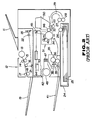
- This type of conventional facsimile apparatus has a structure shown in Fig. 2. A reading system and a recording system in this apparatus will now be described.
- a document placed on a paper feed table 11 is transferred through a scanner section 12 in the following order: a roller 13 ⁇ between rollers 14 and 15 ⁇ a roller 16 ⁇ between rollers 17 and 18.
- the document transferred through the above-described passage is discharged onto a document discharge tray 19.
- the scanner section 12 the document being transferred in a sub-scanning direction is repeatedly read in a main scanning direction through a mirror 21 and a lens system 22 by means of a charge-coupled device image sensor (hereinafter referred to as "CCD image sensor") 23. This causes an image signal corresponding to an image of the document to be output from the CCD image sensor 23.
- CCD image sensor charge-coupled device image sensor
- a piece of recording paper 25 housed in a casette 24 is taken out by a pick-up roller 26 and led to a U-turn guide 29 through between an automatic paper feed roller 27 and a separating roller 28.
- the recording paper is then passed through an electrophotographic process section 31 in the following order: between rollers 32 and 33 ⁇ a photosensitive drum 34. Further, the recording paper is transferred through a fixing section 35 in the following order between rollers for thermal fixation 36 and 37 ⁇ between rollers 38 and 39, and then discharged onto a recording paper discharge tray 41.
- an optical signal corresponding to the image signal is reflected by a polygon mirror 44 of an equilateral prism being rotated by a motor 43 and further reflected by a mirror 45 and applied onto the photosensitive drum 34.
- the photosensitive drum 34 is electrified by a charger 40 and then exposed to the optical signal from the optical signal generating section 42, thereby forming a latent image.
- the latent image on the photosensitive drum 34 is developed by guiding a toner housed in a toner box 50 in the electrophotographic process section 31 to the photosensitive drum 34 with the rotation of the roller 46.
- a toner image formed by the development on the photosensitive drum 34 is transferred on the recording paper being conveyed along the photosensitive drum 34. Further, the recording paper is pressed and heated between the thermal fixing rollers 36 and 37 in the fixing section 35, so that the transferred toner image is fixed.
- Ozone generated within the facsimile apparatus is adsorbed on an ozone adsorption filter 47 and diffused by an ozone diffusing fan 48 for release.
- the optical signal generating section 42 is disposed above the fixing section 35 and the electrophotographic process section 31 juxtaposed to each other, and the scanner section 12 is disposed above the optical signal generating section 42. This requires for the facsimile apparatus to be high, which is detrimental to a reduction in the size. Further, since the optical signal generating section 42 is disposed above the fixing section 35, the heat generated in the fixing section 35 has an adverse effect on the optical signal generating section 42. For example, when a position of a rotation axis of the polygon mirror 44 in the optical signal generating section 42 is deviated even to a small extent by the heat, a path of the optical signal remarkably inclines, which causes lines in the main scanning direction on the photosensitive drum 34 to be remarkably deviated.
- an object of the present invention is to provide a facsimile apparatus which enables a reduction in the height of the apparatus body and avoidance of the influence of heat generated in a fixing section on an optical signal generating section.
- a facsimile apparatus comprising a scanner section adapted for reading a document, an electrophotographic process section including a photosensitive drum and adapted for feeding a toner to the photosensitive drum, an optical signal generating section adapted for applying an optical signal corresponding to an image of the document to the photosensitive drum in the electrophotographic process section, and a fixing section adapted for fixing on recording paper the toner transferred onto the recording paper by the photosensitive drum, wherein the optical signal generating section and the scanner section are juxtaposed to each other in a horizontal direction and the electrophotographic process section and the fixing section are juxtaposed to each other at a position below the optical signal generating section and the scanner section.
- the height of the apparatus body may be small as opposed to the conventional apparatus wherein the optical signal generating section is disposed above the fixing section and the electrophotographic process section, and the scanner section is disposed above the optical signal generating section.
- the electrophotographic process section is disposed below the optical signal generating section and the fixing section is disposed below the scanner section.
- the optical signal generating section is disposed above the electrophotographic process section, the influence of heat generated in the fixing section can be avoided.
- Fig. 1 is a cross-sectional view of one embodiment of the facsimile apparatus according to the present invention.
- portions having the same function as that of corresponding portions of the conventional apparatus shown in Fig. 2 are respectively designated by the same numerals for simplification of explanation of the invention.
- an optical signal generating section 42 is disposed above an electrophotographic process section 31, and a scanner section 12 is disposed above a fixing section 35.
- the electrophotographic process section 31 and the fixing section 35 have respectively the same internal structures as those of the conventional apparatus shown in Fig. 2.
- a lens having a small focal length is used as a lens 1 located between a mirror 21 and a charge-coupled device image sensor (hereinafter referred to as "CCD image sensor") 23.
- CCD image sensor charge-coupled device image sensor
- optical signal generating section 42 an optical signal reflected by a polygon mirror 44 is reflected by a first mirror 2 and further reflected by a second mirror 3, and then guided to the photosensitive drum 34.
- This enables the optical path length of the optical signal to be sufficiently ensured. Therefore, there is no possibility that the scanning distance in the main scanning direction on the photosensitive drum 34 is shortened.
- the optical path of the optical signal is bent twice, i.e., by the first mirror 2 and the second mirror 3, which makes it possible to shorten the length in the horizontal direction of the optical signal generating section 42. This enable the optical signal generating section 42 to be easily housed in the space above the electrophotographic process section 31.
- the fixing section 35 and the electrophotographic process section 31 are disposed below the scanner section 12 and the optical signal generating section 42, respectively.
- optical signal generating section 42 is located away from fixing section 35, the influence of heat generated in fixing section 35 on a rotary optical system can be avoided. Specifically, it is possible to avoid occurrence of such a phenomenon that the heat generated in fixing section 35 is directly transferred to optical signal generating section 42 or heated air ascending from fixing section 35 surrounds optical signal generating section 42. Scanner section 12 is located above fixing section 35 and therefore cannot avoid the influence of the heat. However, there occurs no significant disorder of the optical system because no rotary optical system is used in this section.
- juxtaposition of the optical signal generating section and the scanner section to each other in the horizontal direction and juxtaposition of the electrophotographic process section and the fixing section to each other below the optical signal generating section and the scanner section enable the height of the apparatus body to be reduced. Further, the influence of the heat generated in the fixing section on the optical signal generating section can be avoided in such a manner that the optical signal generating section is not disposed above the fixing section.
Landscapes
- Engineering & Computer Science (AREA)
- Multimedia (AREA)
- Signal Processing (AREA)
- Facsimiles In General (AREA)
- Facsimile Scanning Arrangements (AREA)
- Electrophotography Configuration And Component (AREA)
- Fixing For Electrophotography (AREA)
- Combination Of More Than One Step In Electrophotography (AREA)
Applications Claiming Priority (2)
| Application Number | Priority Date | Filing Date | Title |
|---|---|---|---|
| JP32278/89U | 1989-03-22 | ||
| JP1989032278U JPH0715231Y2 (ja) | 1989-03-22 | 1989-03-22 | ファクシミリ装置 |
Publications (2)
| Publication Number | Publication Date |
|---|---|
| EP0389285A2 true EP0389285A2 (fr) | 1990-09-26 |
| EP0389285A3 EP0389285A3 (fr) | 1992-01-02 |
Family
ID=12354512
Family Applications (1)
| Application Number | Title | Priority Date | Filing Date |
|---|---|---|---|
| EP19900303099 Ceased EP0389285A3 (fr) | 1989-03-22 | 1990-03-22 | Appareil de fac-similé |
Country Status (3)
| Country | Link |
|---|---|
| EP (1) | EP0389285A3 (fr) |
| JP (1) | JPH0715231Y2 (fr) |
| CA (1) | CA2012458C (fr) |
Cited By (5)
| Publication number | Priority date | Publication date | Assignee | Title |
|---|---|---|---|---|
| EP0502711A3 (en) * | 1991-03-05 | 1993-03-03 | Canon Kabushiki Kaisha | Image reading apparatus |
| EP0606628A3 (fr) * | 1992-12-22 | 1994-07-27 | Canon Kabushiki Kaisha | Appareil d'enregistrement |
| EP0579167A3 (en) * | 1992-07-13 | 1994-08-24 | Mita Industrial Co Ltd | An image forming apparatus capable of opening a main body on one side |
| EP0579168A3 (fr) * | 1992-07-13 | 1995-05-03 | Mita Industrial Co Ltd | Dispositif d'avancement de feuilles avec des moyens de retournement de feuilles. |
| US6059281A (en) * | 1996-10-03 | 2000-05-09 | Canon Kabushiki Kaisha | Sheet feeding apparatus |
Families Citing this family (1)
| Publication number | Priority date | Publication date | Assignee | Title |
|---|---|---|---|---|
| JP2538162B2 (ja) * | 1992-05-21 | 1996-09-25 | 松下電送株式会社 | 画像通信装置 |
Family Cites Families (7)
| Publication number | Priority date | Publication date | Assignee | Title |
|---|---|---|---|---|
| JPS62207064A (ja) * | 1986-03-07 | 1987-09-11 | Toshiba Corp | フアクシミリ装置 |
| JPS62279772A (ja) * | 1986-05-28 | 1987-12-04 | Konica Corp | デジタル画像形成装置 |
| US4868672A (en) * | 1986-09-29 | 1989-09-19 | Kabushiki Kaisha Toshiba | Image reading device having a document handling system |
| JPS63204866A (ja) * | 1987-02-20 | 1988-08-24 | Toshiba Corp | フアクシミリ装置 |
| JPS63267058A (ja) * | 1987-04-24 | 1988-11-04 | Brother Ind Ltd | 複写機能を備えたフアクシミリ装置 |
| JPS63191748U (fr) * | 1987-05-15 | 1988-12-09 | ||
| JPS63296952A (ja) * | 1987-05-29 | 1988-12-05 | Ricoh Co Ltd | プリンタ |
-
1989
- 1989-03-22 JP JP1989032278U patent/JPH0715231Y2/ja not_active Expired - Lifetime
-
1990
- 1990-03-19 CA CA 2012458 patent/CA2012458C/fr not_active Expired - Fee Related
- 1990-03-22 EP EP19900303099 patent/EP0389285A3/fr not_active Ceased
Cited By (8)
| Publication number | Priority date | Publication date | Assignee | Title |
|---|---|---|---|---|
| EP0502711A3 (en) * | 1991-03-05 | 1993-03-03 | Canon Kabushiki Kaisha | Image reading apparatus |
| US5633732A (en) * | 1991-03-05 | 1997-05-27 | Canon Kabushiki Kaisha | Image reading apparatus having a partition module between an image sensor module and a heat source |
| EP0579167A3 (en) * | 1992-07-13 | 1994-08-24 | Mita Industrial Co Ltd | An image forming apparatus capable of opening a main body on one side |
| EP0579168A3 (fr) * | 1992-07-13 | 1995-05-03 | Mita Industrial Co Ltd | Dispositif d'avancement de feuilles avec des moyens de retournement de feuilles. |
| US5456456A (en) * | 1992-07-13 | 1995-10-10 | Mita Industrial Co., Ltd. | Paper feeding device having paper inverting means |
| EP0606628A3 (fr) * | 1992-12-22 | 1994-07-27 | Canon Kabushiki Kaisha | Appareil d'enregistrement |
| US6102506A (en) * | 1992-12-22 | 2000-08-15 | Canon Kabushiki Kaisha | Recording apparatus |
| US6059281A (en) * | 1996-10-03 | 2000-05-09 | Canon Kabushiki Kaisha | Sheet feeding apparatus |
Also Published As
| Publication number | Publication date |
|---|---|
| EP0389285A3 (fr) | 1992-01-02 |
| JPH02123166U (fr) | 1990-10-09 |
| CA2012458C (fr) | 1995-08-08 |
| JPH0715231Y2 (ja) | 1995-04-10 |
Similar Documents
| Publication | Publication Date | Title |
|---|---|---|
| CA2012458C (fr) | Appareil de telecopie | |
| US4560866A (en) | Image pick-up apparatus with folding optics | |
| JP2003083348A (ja) | 駆動機構の軸受構造、画像読取装置および画像形成装置 | |
| JP2000028944A (ja) | 光学装置 | |
| CA1294314C (fr) | Appareil de telecopie | |
| US6369875B1 (en) | Slidable assembly including slider pieces with an upper and lower part | |
| EP0902335B1 (fr) | Appareil de lecture d'images | |
| JP2017032866A (ja) | 光走査装置 | |
| JPS6363272A (ja) | 読取装置 | |
| JPH09251228A (ja) | 画像形成装置 | |
| US5072260A (en) | Image forming apparatus having analog and digital exposure means | |
| JP3215226B2 (ja) | 画像読取装置 | |
| JPS6320957A (ja) | 読取装置 | |
| JPH01193752A (ja) | デジタル複写機 | |
| JP2022166462A (ja) | 読み取り装置及び画像形成装置 | |
| JPS6238657A (ja) | 光走査装置 | |
| JPH0359614A (ja) | 電子写真装置のレーザビーム走査装置 | |
| JPH01192662A (ja) | デジタル複写機 | |
| JPH0438350B2 (fr) | ||
| JPH01231064A (ja) | デジタル複写機 | |
| JPS6320958A (ja) | 読取装置 | |
| JPH07106643B2 (ja) | 画像記録装置 | |
| JPH01191871A (ja) | デジタル複写機 | |
| JPH01191863A (ja) | デジタル複写機 | |
| JPH0732445B2 (ja) | 多モード走査装置用プラテン |
Legal Events
| Date | Code | Title | Description |
|---|---|---|---|
| PUAI | Public reference made under article 153(3) epc to a published international application that has entered the european phase |
Free format text: ORIGINAL CODE: 0009012 |
|
| 17P | Request for examination filed |
Effective date: 19900417 |
|
| AK | Designated contracting states |
Kind code of ref document: A2 Designated state(s): DE FR GB |
|
| PUAL | Search report despatched |
Free format text: ORIGINAL CODE: 0009013 |
|
| AK | Designated contracting states |
Kind code of ref document: A3 Designated state(s): DE FR GB |
|
| 17Q | First examination report despatched |
Effective date: 19940325 |
|
| STAA | Information on the status of an ep patent application or granted ep patent |
Free format text: STATUS: THE APPLICATION HAS BEEN REFUSED |
|
| 18R | Application refused |
Effective date: 19960307 |