EP0389295A1 - Dispositif pour produire une image stéréoscopique - Google Patents
Dispositif pour produire une image stéréoscopique Download PDFInfo
- Publication number
- EP0389295A1 EP0389295A1 EP90303135A EP90303135A EP0389295A1 EP 0389295 A1 EP0389295 A1 EP 0389295A1 EP 90303135 A EP90303135 A EP 90303135A EP 90303135 A EP90303135 A EP 90303135A EP 0389295 A1 EP0389295 A1 EP 0389295A1
- Authority
- EP
- European Patent Office
- Prior art keywords
- forming apparatus
- stereo image
- image forming
- image taking
- distance
- Prior art date
- Legal status (The legal status is an assumption and is not a legal conclusion. Google has not performed a legal analysis and makes no representation as to the accuracy of the status listed.)
- Granted
Links
Images


Classifications
-
- G—PHYSICS
- G03—PHOTOGRAPHY; CINEMATOGRAPHY; ANALOGOUS TECHNIQUES USING WAVES OTHER THAN OPTICAL WAVES; ELECTROGRAPHY; HOLOGRAPHY
- G03B—APPARATUS OR ARRANGEMENTS FOR TAKING PHOTOGRAPHS OR FOR PROJECTING OR VIEWING THEM; APPARATUS OR ARRANGEMENTS EMPLOYING ANALOGOUS TECHNIQUES USING WAVES OTHER THAN OPTICAL WAVES; ACCESSORIES THEREFOR
- G03B35/00—Stereoscopic photography
- G03B35/08—Stereoscopic photography by simultaneous recording
-
- H—ELECTRICITY
- H04—ELECTRIC COMMUNICATION TECHNIQUE
- H04N—PICTORIAL COMMUNICATION, e.g. TELEVISION
- H04N13/00—Stereoscopic video systems; Multi-view video systems; Details thereof
- H04N13/20—Image signal generators
- H04N13/204—Image signal generators using stereoscopic image cameras
- H04N13/239—Image signal generators using stereoscopic image cameras using two two-dimensional [2D] image sensors having a relative position equal to or related to the interocular distance
-
- H—ELECTRICITY
- H04—ELECTRIC COMMUNICATION TECHNIQUE
- H04N—PICTORIAL COMMUNICATION, e.g. TELEVISION
- H04N13/00—Stereoscopic video systems; Multi-view video systems; Details thereof
- H04N13/20—Image signal generators
- H04N13/296—Synchronisation thereof; Control thereof
-
- H—ELECTRICITY
- H04—ELECTRIC COMMUNICATION TECHNIQUE
- H04N—PICTORIAL COMMUNICATION, e.g. TELEVISION
- H04N13/00—Stereoscopic video systems; Multi-view video systems; Details thereof
- H04N13/30—Image reproducers
- H04N13/332—Displays for viewing with the aid of special glasses or head-mounted displays [HMD]
- H04N13/337—Displays for viewing with the aid of special glasses or head-mounted displays [HMD] using polarisation multiplexing
-
- H—ELECTRICITY
- H04—ELECTRIC COMMUNICATION TECHNIQUE
- H04N—PICTORIAL COMMUNICATION, e.g. TELEVISION
- H04N13/00—Stereoscopic video systems; Multi-view video systems; Details thereof
- H04N13/10—Processing, recording or transmission of stereoscopic or multi-view image signals
- H04N13/194—Transmission of image signals
Definitions
- the present invention relates to a stereo image forming apparatus, and more particularly to such stereo image forming apparatus for enabling, in observing a stereo image for example with television images obtained by two television cameras mutually distanced by a predetermined base line, observation of satisfactory stereo image easily and promptly over the entire distance range from the infinite distance to a very short distance, by a simple method.
- observation of a stereo image has been achieved by placing two image taking systems with a mutual distance of the optical axes thereof corresponding to the distance of the eyes (parallax or base line length) of the observer, and observing two images obtained by said two image taking system respectively with left and right eyes.
- Fig. 5 is a schematic view of a conventional stereo image forming apparatus for observing a stereo image with television images.
- Television cameras 51, 52 are rotatably positioned with a mutual distance corresponding to a predetermined base line length.
- Television receivers 53, 54 respectively corresponding to the television cameras 51, 52 provide slightly different images with a parallax.
- polarizing filters 55, 56 with mutually perpendicular polarizing directions; a half mirror 57; polarizing glasses 58 in which the polarizing direction of a polarizing filter 58a for the right eye is parallel to that of the polarizing filter 55 while the polarizing direction of a polarizing filter 58b for the left eye is parallel to that of the polarizing filter 56; an object 59 to be observed; and an observer 60.
- the left eye observes the image of the television receiver 54 only, while the right eye observes the image of the television receiver 53 only, by means of the polarizing filters, whereby the observer can observe a stereo image of the object 59 viewed by the television cameras 51, 52.
- the two television cameras 51, 52 are rotated by unrepresented driving means in such a manner that the optical axes of the image taking system are directed to the object 59, as indicated by broken lines.
- the television cameras rotated by driving means in such a manner that the optical axes of the image taking systems are directed to the object when the distance thereof varies.
- the object of the present invention is to provide a stereo image forming apparatus capable of easily, promptly and precisely directing the optical axes of two image taking systems to the object when the distance of the object of which stereo image is to be observed varies, thereby adapted for use in case of observing the stereo image for example with television cameras generally involving bulky image taking system.
- the stereo image forming apparatus of the present invention for observing a stereo image with two images obtained from two image taking systems, is provided with the two image taking system arranged by a predetermined base length therebetween and deflection members, having two wedge-shaped prisms rotatable in mutually opposite directions, on the optical axis and in front of each of said two image taking system, linking the rotating operation of said wedge-shaped prisms of the deflection members with the focusing operation of a focusing lens unit of said image taking system, wherein the object distance at which the image taking system is focused by rotative movement of the focusing lens unit thereof coincides substantially with the crossing point of the optical path of the rays of light deflected from the optical axes of two image taking systems by the rotation of two wedge-shaped prisms constituting the deflection members.
- Fig. 1 is a schematic view of the principal part of an embodiment of the present invention applied to television cameras for observing a stereo television image.
- a deflection member 11 (12) is positioned in front of an image taking system 1 (2) to be explained later, and is composed of two wedge-shaped prisms 11a, 11b (12a, 12b) of a same vertical angle, combined so as to be rotatable in mutually opposite directions.
- two prisms 11a, 11b (12a, 12b) are so positioned as to constitute two parallel planes in a reference state (directed to an object at the infinite distance).
- Image taking system 1, 2 are composed of zoom lenses or lenses of a fixed focal length, and are so arranged that the optical axes 1b, 2b thereof are mutually parallel and separated by a predetermined base line length.
- a focusing lens unit 1a (2a) of the image taking system 1 (2) is rotated and moved along the optical axis 1b (2b) by drive means 13 (14), in linkage with the rotation of the deflection member 11 (12).
- a display unit 3 (4) displays the image of the object 9, obtained through the image taking system 1 (2).
- Polarizing filters 5, 6 are mounted respectively on the display units 3, 4 in such a manner that the polarizing directions thereof are mutually perpendicular.
- a half mirror 7 guides the image on the display unit 3 and that on the display unit 4 toward the observer 10.
- Polarizing glasses 8 is provided with polarizing filters 8a, 8b, respectively for the right and left eyes of the observer 10, so positioned that the polarizing directions thereof are mutually perpendicular.
- the polarizing directions of said two polarizing filters 8a, 8b substantially coincide, respectively, with those of the polarizing filters 5, 6.
- the polarizing direction of the polarizing filter 5 substantially coincides with that of the polarizing filter 8a
- the polarizing direction of the polarizing filter 6 substantially coincides with that of the polarizing filter 8b.
- the right eye of the observer 10 observes only the image of the display unit 3 obtained by the image taking system 1, while the left eye observes only the image of the display unit 4 obtained by the image taking system 2, whereby the observer can observe the stereo image.
- a focusing operation unit 15 electrically drives two drive means 13 and 14 to simultaneously rotate the focusing lens units 1a and 2a thereby axially moving the same, and to rotate the prisms 11a, 11b (12a, 12b) of the deflection member 11 (12) in mutually opposite directions.
- two prisms 11a, 11b (12a, 12b) of the deflection member 11 (12) are so positioned as to integrally constitute parallel planes when the observed object 9 is at the infinite distance. Also the focusing lens unit 1a (2a) of the image taking system 1 (2) is naturally focused to the infinite distance in such state.
- the observer electrically or manually drives the drive means 13 (14) by the focusing lens operation unit 15, thereby axially moving the focusing unit 1a (2a) of the image taking system 1 (2) so as to be focused to the observed object.
- the prisms 11a, 11b of the deflection member 11 (12) are rotated in mutually opposite directions, thereby giving a certain vertical angle integrally to said prisms and deflecting the light.
- the image taking system is not rotated toward the object as in the conventional system but is fixed. Instead, when the focusing unit is axially moved, two prisms constituting the deflection member in front of the image taking system are rotated in mutually opposite directions in linkage. It is therefore made possible, without complication in the mechanism, to easily and promptly obtain a focused image of the object on each display unit, even when the distance to the object varies from time to time.
- the lights from the display unit 3, 4 are respectively guided to the right and left eyes of the observer, there enabling to observe the stereo television image.
- the components are preferably so designed that the linear relationship exists in the linkage between the rotating operation of the focusing unit of the image taking system and the rotating operation of the prisms of the deflection member, or the purpose of simplifying the mechanism, but such linear relationship is not indispensable.
- a rotation link member (corresponding to an intermediate ring) for linking the rotation of the focusing unit and of the deflection member.
- Fig. 2 is a schematic cross-sectional view of the deflection member 11 of the present invention.
- two prisms 11a, 11b of the deflection member 11 are optically identical, and each prism is composed of mutually adhered two small prisms 11a1, 11a2 (11b1, 11b2) of different materials for reducing the color aberration in the prism action.
- Fig. 4 is a schematic view of a focusing cam groove 1e provided on a lens barrel 1d supporting the above-mentioned focusing unit 1a, for axially moving said focusing unit, in the image taking system of the present embodiment.
- the focal length of the focusing unit and the shape of the focusing cam groove 1e on the lens barrel are so determined that, in the focusing operation by rotation of the lens barrel 1d, the object distance to which the focusing unit is focused coincides substantially with the observed object distance determined by the deflection members 11, 12 rotated in linkage with the focusing unit.
- the lens barrel 1d is made rotatable by 90° from the reference position (0° for the object at infinite distance) like the deflection members 11, 12, and this rotation causes the movement of the focusing unit by 7.09 mm in the axial direction as will be explained later.
- the focusing unit is so controlled that, when rotated by an angle ⁇ same as that of the deflection member 11 shown in Table 2, the system is focused to the object distance defined by the deflection members.
- Table 2 also shows the rotation angle ⁇ of the lens barrel 1d, and the amount ⁇ x of advancement of the focusing unit.
- the two prisms of the deflection member need not necessarily be rotated by 90°, but may be stopped on the way (for example at about 80°). In such case the rotation of the focusing unit of the image taking system may likewise be stopped on the way.
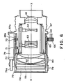
- Fig . 6 is a schematic view of an embodiment, showing the mechanism for exploiting the present invention. Though there are provided two image taking systems 60, 61 in parallal, only one of said systems is shown in detail, since they have identical internal structure.
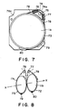
- Fig. 7 is a schematic front view of said image taking system 60 or 61.
- a focusing lens 62 there are shown a focusing lens 62, a variator lens 63, a compensator lens 64, and a relay lens 65.
- a focusing gear 66 rotated by an unrepresented driving mechanism; a fixed lens barrel 67; and a driving cam tube 68 provided therearound with gears 69, 69′ meshing with the focusing gears 66 for synchronously driving the image taking system 60, 61.
- Said driving cam tube 68 is slidable in the axial direction x, with respect to the fixed lens barrel 67.
- a cam groove 68a is provided on the cam tube 68, with a shape as shown in Fig. 4.
- a cam pin 70 fixed on the fixed lens barrel 67 engages with the cam groove.
- Another pin 71 is provided for preventing the rotation of the lens barrel in excess of 90°.
- a lens supporting tube 72 supports the focusing lens 62 and a wedge-shaped prism 11b, and is coupled with said driving cam tube 68 for integral rotational and axial movements. However the lens supporting tube 72 and the driving cam tube 68 are helicoid coupled for initial position setting of the lens.
- a prism supporting tube 73 supports the other wedge-shaped prism 11a and is rotatably fitted on the lens supporting tube 72.
- a slidable bearing 74 with axially movable shaft 74a, is mounted on a protruding portion 67a of the fixed lens barrel 67.
- a pulley mounting member 75 fixed on the shaft 74a, rotatably supports pulleys 76, 77.
- a wire 78 runs on said pulleys 76, 77 and runs around the lens supporting tube 72 and the prism supporting tube 73 in criss-cross manner as shown in Fig. 8. Since said wire 78 is fixed to the prism supporting tube 73 and the lens supporting tube 72 respectively by fixing members 79, 88, the rotation of the lens supporting tube 72 causes an inverse rotation of the prism supporting tube 73 in 1 : 1 relationship.
- the driving mechanism for the variator lens 63 and the compensator lens 64 is already known and will therefore be omitted from explanation.
- the rotation of the focusing gear 66 causes the rotation of the gear 69 (69′) meshing therewith, thereby rotating the driving cam tube 68.
- the driving cam tube 68 moves in the axial direction x according to the cam lift.
- the lens supporting tube 72 fixed to the driving cam tube 68 performs rotation as well as axial movement.
- the rotation of the lens supporting tube 72 induces the rotation of the prism supporting tube 73 as explained before, thus inducing differential rotation of the wedge-shaped prisms 11a, 11b.
- the embodiment of the present invention in which deflection members each composed of two prisms of a predetermined shape are positioned respectively in front of two image taking systems arranged with mutually parallel optical axes and said two prisms of the deflection member are rotated in linkage with the focusing unit of the image taking system, can provide a stereo image forming apparatus which allows easy and prompt focusing to the object of varying distance without rotation of the image taking systems, thereby enabling to observe a satisfactory stereo image.
Landscapes
- Engineering & Computer Science (AREA)
- Multimedia (AREA)
- Signal Processing (AREA)
- Physics & Mathematics (AREA)
- General Physics & Mathematics (AREA)
- Testing, Inspecting, Measuring Of Stereoscopic Televisions And Televisions (AREA)
- Stereoscopic And Panoramic Photography (AREA)
Applications Claiming Priority (2)
| Application Number | Priority Date | Filing Date | Title |
|---|---|---|---|
| JP72459/89 | 1989-03-24 | ||
| JP1072459A JP2765022B2 (ja) | 1989-03-24 | 1989-03-24 | 立体画像形成装置 |
Publications (2)
| Publication Number | Publication Date |
|---|---|
| EP0389295A1 true EP0389295A1 (fr) | 1990-09-26 |
| EP0389295B1 EP0389295B1 (fr) | 1994-06-08 |
Family
ID=13489908
Family Applications (1)
| Application Number | Title | Priority Date | Filing Date |
|---|---|---|---|
| EP90303135A Expired - Lifetime EP0389295B1 (fr) | 1989-03-24 | 1990-03-23 | Dispositif pour produire une image stéréoscopique |
Country Status (4)
| Country | Link |
|---|---|
| US (1) | US5486948A (fr) |
| EP (1) | EP0389295B1 (fr) |
| JP (1) | JP2765022B2 (fr) |
| DE (1) | DE69009556T2 (fr) |
Cited By (1)
| Publication number | Priority date | Publication date | Assignee | Title |
|---|---|---|---|---|
| EP0452822A1 (fr) * | 1990-04-20 | 1991-10-23 | Leica AG | Microscope d'opération pour au moins deux chirurgiens |
Families Citing this family (53)
| Publication number | Priority date | Publication date | Assignee | Title |
|---|---|---|---|---|
| JP2685619B2 (ja) * | 1989-04-28 | 1997-12-03 | 池上通信機株式会社 | 立体カメラのビューファインダ装置 |
| JP3220538B2 (ja) * | 1992-12-24 | 2001-10-22 | オリンパス光学工業株式会社 | 立体視内視鏡及び立体視内視鏡装置 |
| JP2513403B2 (ja) * | 1993-06-08 | 1996-07-03 | 日本電気株式会社 | 投射型立体表示装置 |
| US6177952B1 (en) | 1993-09-17 | 2001-01-23 | Olympic Optical Co., Ltd. | Imaging apparatus, image display apparatus and image recording and/or reproducing apparatus |
| JPH08145676A (ja) * | 1994-09-19 | 1996-06-07 | Asahi Optical Co Ltd | 基準平面形成用レーザ投光装置 |
| US5880883A (en) * | 1994-12-07 | 1999-03-09 | Canon Kabushiki Kaisha | Apparatus for displaying image recognized by observer as stereoscopic image, and image pick-up apparatus |
| US5703664A (en) * | 1995-10-23 | 1997-12-30 | Motorola, Inc. | Integrated electro-optic package for reflective spatial light modulators |
| US6052223A (en) * | 1996-01-09 | 2000-04-18 | Olympus Optical Co., Ltd. | Microscope with chromatic aberration correcting function |
| WO2000041399A1 (fr) * | 1999-01-06 | 2000-07-13 | Hideyoshi Horimai | Dispositif et procede de detection d'une image tridimensionnelle, dispositif et procede d'affichage d'une image tridimensionnelle, et dispositif et procede permettant de changer la position d'une image tridimensionnelle |
| US6429982B2 (en) * | 1999-07-30 | 2002-08-06 | Applied Materials, Inc. | Counter-rotating anamorphic prism assembly with variable spacing |
| DE69912858T2 (de) * | 1999-09-08 | 2004-08-26 | Nederlandse Organisatie Voor Toegepast-Natuurwetenschappelijk Onderzoek Tno | Achromatisches phasenverschiebungsgerät und zugehöriges interferometer |
| AT409042B (de) * | 1999-11-24 | 2002-05-27 | Life Optics Handel Und Vertrie | Sehhilfe |
| US6099124A (en) * | 1999-12-14 | 2000-08-08 | Hidaji; Faramarz | Ophthalmological system and method |
| WO2001050947A1 (fr) * | 2000-01-14 | 2001-07-19 | Intuitive Surgical, Inc. | Endoscope |
| DE10018253C2 (de) * | 2000-04-13 | 2003-08-21 | Leica Microsystems | Laser-Mikro-Dissektionsgerät |
| DE10030196C2 (de) * | 2000-06-22 | 2002-05-08 | 4D Vision Gmbh | Anordnung und Verfahren zur Aufnahme von mehreren Ansichten einer Szene oder eines Gegenstandes |
| EP1177734B1 (fr) * | 2000-08-03 | 2005-09-14 | CEO Centro di Eccellenza Optronica | Casque de protection muni d'un système rétroviseur |
| EP1177733A1 (fr) * | 2000-08-03 | 2002-02-06 | CEO Centro di Eccellenza Optronica | Casque de protection muni d'un système rétroviseur |
| US6704143B1 (en) * | 2000-10-23 | 2004-03-09 | Adc Telecommunications, Inc. | Method and apparatus for adjusting an optical element to achieve a precise length |
| US6747686B1 (en) | 2001-10-05 | 2004-06-08 | Recon/Optical, Inc. | High aspect stereoscopic mode camera and method |
| FR2838598B1 (fr) * | 2002-04-11 | 2004-10-29 | Comex Nucleaire | Procede et dispositif de television stereoscopique |
| US7057795B2 (en) * | 2002-08-20 | 2006-06-06 | Silicon Light Machines Corporation | Micro-structures with individually addressable ribbon pairs |
| US7424133B2 (en) | 2002-11-08 | 2008-09-09 | Pictometry International Corporation | Method and apparatus for capturing, geolocating and measuring oblique images |
| JP2005250363A (ja) * | 2004-03-08 | 2005-09-15 | Nitto Kogaku Kk | 双眼拡大鏡 |
| US7873238B2 (en) | 2006-08-30 | 2011-01-18 | Pictometry International Corporation | Mosaic oblique images and methods of making and using same |
| US8593518B2 (en) * | 2007-02-01 | 2013-11-26 | Pictometry International Corp. | Computer system for continuous oblique panning |
| US8520079B2 (en) * | 2007-02-15 | 2013-08-27 | Pictometry International Corp. | Event multiplexer for managing the capture of images |
| US8385672B2 (en) * | 2007-05-01 | 2013-02-26 | Pictometry International Corp. | System for detecting image abnormalities |
| US9262818B2 (en) | 2007-05-01 | 2016-02-16 | Pictometry International Corp. | System for detecting image abnormalities |
| US7991226B2 (en) | 2007-10-12 | 2011-08-02 | Pictometry International Corporation | System and process for color-balancing a series of oblique images |
| US8531472B2 (en) | 2007-12-03 | 2013-09-10 | Pictometry International Corp. | Systems and methods for rapid three-dimensional modeling with real façade texture |
| US8588547B2 (en) | 2008-08-05 | 2013-11-19 | Pictometry International Corp. | Cut-line steering methods for forming a mosaic image of a geographical area |
| US8401222B2 (en) | 2009-05-22 | 2013-03-19 | Pictometry International Corp. | System and process for roof measurement using aerial imagery |
| US9330494B2 (en) | 2009-10-26 | 2016-05-03 | Pictometry International Corp. | Method for the automatic material classification and texture simulation for 3D models |
| US8477190B2 (en) | 2010-07-07 | 2013-07-02 | Pictometry International Corp. | Real-time moving platform management system |
| US8823732B2 (en) | 2010-12-17 | 2014-09-02 | Pictometry International Corp. | Systems and methods for processing images with edge detection and snap-to feature |
| WO2013106080A2 (fr) | 2011-06-10 | 2013-07-18 | Pictometry International Corp. | Système et procédé pour former un flux vidéo contenant des données gis en temps réel |
| DE102011054087B4 (de) | 2011-09-30 | 2018-08-30 | Carl Zeiss Microscopy Gmbh | Optische Bildstabilisierungsvorrichtung und optisches Beobachtungsgerät |
| US9183538B2 (en) | 2012-03-19 | 2015-11-10 | Pictometry International Corp. | Method and system for quick square roof reporting |
| US9244272B2 (en) | 2013-03-12 | 2016-01-26 | Pictometry International Corp. | Lidar system producing multiple scan paths and method of making and using same |
| US9881163B2 (en) | 2013-03-12 | 2018-01-30 | Pictometry International Corp. | System and method for performing sensitive geo-spatial processing in non-sensitive operator environments |
| US9753950B2 (en) | 2013-03-15 | 2017-09-05 | Pictometry International Corp. | Virtual property reporting for automatic structure detection |
| US9275080B2 (en) | 2013-03-15 | 2016-03-01 | Pictometry International Corp. | System and method for early access to captured images |
| CA2935457C (fr) | 2014-01-10 | 2022-08-09 | Pictometry International Corp. | Systeme et procede d'evaluation de structure d'aeronef sans pilote |
| US9292913B2 (en) | 2014-01-31 | 2016-03-22 | Pictometry International Corp. | Augmented three dimensional point collection of vertical structures |
| CA2938973A1 (fr) | 2014-02-08 | 2015-08-13 | Pictometry International Corp. | Procede et systeme d'affichage d'interieurs de pieces sur un plan |
| KR101476820B1 (ko) * | 2014-04-07 | 2014-12-29 | 주식회사 썸텍 | 3d 비디오 현미경 장치 |
| US9983384B2 (en) * | 2014-04-20 | 2018-05-29 | Lenny Lipton | Stereoscopic lens for digital cameras |
| CA3001023A1 (fr) | 2016-01-08 | 2017-07-13 | Pictometry International Corp. | Systemes et procedes permettant de prendre, traiter, recuperer et afficher des images d'aeronefs sans pilote |
| US10402676B2 (en) | 2016-02-15 | 2019-09-03 | Pictometry International Corp. | Automated system and methodology for feature extraction |
| US10671648B2 (en) | 2016-02-22 | 2020-06-02 | Eagle View Technologies, Inc. | Integrated centralized property database systems and methods |
| US10539786B2 (en) * | 2016-05-27 | 2020-01-21 | Verily Life Sciences Llc | Rotatable prisms for controlling dispersion magnitude and orientation and methods of use |
| ES2968959T3 (es) | 2018-11-21 | 2024-05-14 | Eagle View Tech Inc | Aeronave no tripulada de navegación que utiliza cabeceo |
Citations (4)
| Publication number | Priority date | Publication date | Assignee | Title |
|---|---|---|---|---|
| DE2115303A1 (de) * | 1971-03-30 | 1972-10-12 | Nehrkorn, Ingo, 2000 Hamburg | Vorrichtung zum Aufnehmen und Wiedergeben plastischer Bilder, insbesondere bei Benutzung von Aufnahme- und Wiedergabegeräten mit Objektiven veränderbarer Brennweite |
| EP0071531A1 (fr) * | 1981-07-27 | 1983-02-09 | James Linick | Appareil de balayage pour systèmes infra-rouges en avant |
| GB2107869A (en) * | 1981-10-29 | 1983-05-05 | Stanford Res Inst Int | Real time stereo imaging system |
| EP0174091A1 (fr) * | 1984-08-29 | 1986-03-12 | United Kingdom Atomic Energy Authority | Caméra stéréoscopique |
Family Cites Families (11)
| Publication number | Priority date | Publication date | Assignee | Title |
|---|---|---|---|---|
| US2767629A (en) * | 1953-04-21 | 1956-10-23 | Paillard Sa | Optical device for a stereoscopic camera with a horizontal movement of the film |
| SU506954A1 (ru) * | 1973-05-10 | 1976-03-15 | Предприятие П/Я Р-6476 | Стереоскопическа телевизионна камера |
| US3990087A (en) * | 1974-10-21 | 1976-11-02 | Marks Alvin M | 3-Dimensional camera |
| JPS5762687A (en) * | 1980-10-02 | 1982-04-15 | Matsushita Electric Ind Co Ltd | Image pickup device |
| AU552204B2 (en) * | 1980-12-08 | 1986-05-22 | Meier, W. | Optical system for obtaining two compressed images by anamor phosis corrolated at the inter-ocular distance |
| US4418993A (en) * | 1981-05-07 | 1983-12-06 | Stereographics Corp. | Stereoscopic zoom lens system for three-dimensional motion pictures and television |
| US4464028A (en) * | 1981-11-17 | 1984-08-07 | Condon Chris J | Motion picture system for single strip 3-D filming |
| DE3212691A1 (de) * | 1982-04-05 | 1983-10-06 | Zeiss Carl Fa | Prismenkompensator fuer stereoskopische beobachtungsgeraete |
| IL69975A (en) * | 1983-10-16 | 1988-01-31 | Yeda Res & Dev | Stereoscopic optical device |
| JPS61101883A (ja) * | 1984-10-25 | 1986-05-20 | Canon Inc | 輻輳角整合装置 |
| US4744633A (en) * | 1986-02-18 | 1988-05-17 | Sheiman David M | Stereoscopic viewing system and glasses |
-
1989
- 1989-03-24 JP JP1072459A patent/JP2765022B2/ja not_active Expired - Fee Related
-
1990
- 1990-03-23 EP EP90303135A patent/EP0389295B1/fr not_active Expired - Lifetime
- 1990-03-23 DE DE69009556T patent/DE69009556T2/de not_active Expired - Fee Related
-
1994
- 1994-05-16 US US08/243,515 patent/US5486948A/en not_active Expired - Lifetime
Patent Citations (4)
| Publication number | Priority date | Publication date | Assignee | Title |
|---|---|---|---|---|
| DE2115303A1 (de) * | 1971-03-30 | 1972-10-12 | Nehrkorn, Ingo, 2000 Hamburg | Vorrichtung zum Aufnehmen und Wiedergeben plastischer Bilder, insbesondere bei Benutzung von Aufnahme- und Wiedergabegeräten mit Objektiven veränderbarer Brennweite |
| EP0071531A1 (fr) * | 1981-07-27 | 1983-02-09 | James Linick | Appareil de balayage pour systèmes infra-rouges en avant |
| GB2107869A (en) * | 1981-10-29 | 1983-05-05 | Stanford Res Inst Int | Real time stereo imaging system |
| EP0174091A1 (fr) * | 1984-08-29 | 1986-03-12 | United Kingdom Atomic Energy Authority | Caméra stéréoscopique |
Cited By (1)
| Publication number | Priority date | Publication date | Assignee | Title |
|---|---|---|---|---|
| EP0452822A1 (fr) * | 1990-04-20 | 1991-10-23 | Leica AG | Microscope d'opération pour au moins deux chirurgiens |
Also Published As
| Publication number | Publication date |
|---|---|
| JPH02276395A (ja) | 1990-11-13 |
| US5486948A (en) | 1996-01-23 |
| JP2765022B2 (ja) | 1998-06-11 |
| DE69009556D1 (de) | 1994-07-14 |
| EP0389295B1 (fr) | 1994-06-08 |
| DE69009556T2 (de) | 1994-09-29 |
Similar Documents
| Publication | Publication Date | Title |
|---|---|---|
| EP0389295A1 (fr) | Dispositif pour produire une image stéréoscopique | |
| US3972056A (en) | Varifocal lens assembly | |
| US4448498A (en) | Operation microscope | |
| US6069733A (en) | Stereomicroscope | |
| US9667845B2 (en) | Variable 3-dimensional adaptor assembly for camera | |
| EP0396128A2 (fr) | Projecteur catadioptrique, système et procédé de projection catadioptrique | |
| US9389498B2 (en) | 3D-image pickup optical system and 3D-image pickup apparatus | |
| US5825535A (en) | Pancratic magnification system | |
| US20050052755A1 (en) | Dual-band lens | |
| JPH06194580A (ja) | 立体視内視鏡及び立体視内視鏡装置 | |
| JP2004109554A (ja) | 実体顕微鏡用撮影装置 | |
| CN101932966B (zh) | 望远镜及双眼机身构件 | |
| US6059721A (en) | Endoscope having variable magnification and focusing | |
| GB2065325A (en) | Binocular viewing device | |
| GB1260653A (en) | Improvements in or relating to optical apparatus | |
| CN207488610U (zh) | 3d手术显微镜光学主镜 | |
| DE69426246T2 (de) | Optische Vorrichtung mit einer Funktion zur Verhinderung von Bildzittern | |
| JPH07261095A (ja) | 立体視顕微鏡およびその操作方法 | |
| JPS61133928A (ja) | 変倍光学系 | |
| JP3554398B2 (ja) | 内視鏡用立体視アダプター | |
| JP3590425B2 (ja) | 立体視硬性内視鏡 | |
| JPH06347867A (ja) | 実像ファインダー光学系 | |
| JP3355779B2 (ja) | Hmd用光学系 | |
| JP2003107366A (ja) | 撮影機能を有する観察装置 | |
| JPH06308427A (ja) | 立体画像形成装置 |
Legal Events
| Date | Code | Title | Description |
|---|---|---|---|
| PUAI | Public reference made under article 153(3) epc to a published international application that has entered the european phase |
Free format text: ORIGINAL CODE: 0009012 |
|
| AK | Designated contracting states |
Kind code of ref document: A1 Designated state(s): DE FR GB |
|
| 17P | Request for examination filed |
Effective date: 19910222 |
|
| 17Q | First examination report despatched |
Effective date: 19930621 |
|
| GRAA | (expected) grant |
Free format text: ORIGINAL CODE: 0009210 |
|
| AK | Designated contracting states |
Kind code of ref document: B1 Designated state(s): DE FR GB |
|
| REF | Corresponds to: |
Ref document number: 69009556 Country of ref document: DE Date of ref document: 19940714 |
|
| ET | Fr: translation filed | ||
| PLBE | No opposition filed within time limit |
Free format text: ORIGINAL CODE: 0009261 |
|
| STAA | Information on the status of an ep patent application or granted ep patent |
Free format text: STATUS: NO OPPOSITION FILED WITHIN TIME LIMIT |
|
| 26N | No opposition filed | ||
| REG | Reference to a national code |
Ref country code: GB Ref legal event code: IF02 |
|
| PGFP | Annual fee paid to national office [announced via postgrant information from national office to epo] |
Ref country code: FR Payment date: 20050308 Year of fee payment: 16 |
|
| PGFP | Annual fee paid to national office [announced via postgrant information from national office to epo] |
Ref country code: DE Payment date: 20050317 Year of fee payment: 16 |
|
| PGFP | Annual fee paid to national office [announced via postgrant information from national office to epo] |
Ref country code: GB Payment date: 20050323 Year of fee payment: 16 |
|
| PG25 | Lapsed in a contracting state [announced via postgrant information from national office to epo] |
Ref country code: GB Free format text: LAPSE BECAUSE OF NON-PAYMENT OF DUE FEES Effective date: 20060323 |
|
| PG25 | Lapsed in a contracting state [announced via postgrant information from national office to epo] |
Ref country code: DE Free format text: LAPSE BECAUSE OF NON-PAYMENT OF DUE FEES Effective date: 20061003 |
|
| GBPC | Gb: european patent ceased through non-payment of renewal fee |
Effective date: 20060323 |
|
| REG | Reference to a national code |
Ref country code: FR Ref legal event code: ST Effective date: 20061130 |
|
| PG25 | Lapsed in a contracting state [announced via postgrant information from national office to epo] |
Ref country code: FR Free format text: LAPSE BECAUSE OF NON-PAYMENT OF DUE FEES Effective date: 20060331 |