EP0389742A2 - Riementrieb bestehend aus einem Zahnriemen und einer Zahnscheibe - Google Patents
Riementrieb bestehend aus einem Zahnriemen und einer Zahnscheibe Download PDFInfo
- Publication number
- EP0389742A2 EP0389742A2 EP90100620A EP90100620A EP0389742A2 EP 0389742 A2 EP0389742 A2 EP 0389742A2 EP 90100620 A EP90100620 A EP 90100620A EP 90100620 A EP90100620 A EP 90100620A EP 0389742 A2 EP0389742 A2 EP 0389742A2
- Authority
- EP
- European Patent Office
- Prior art keywords
- toothed
- belt
- pulley
- rows
- sections
- Prior art date
- Legal status (The legal status is an assumption and is not a legal conclusion. Google has not performed a legal analysis and makes no representation as to the accuracy of the status listed.)
- Granted
Links
Images
Classifications
-
- F—MECHANICAL ENGINEERING; LIGHTING; HEATING; WEAPONS; BLASTING
- F16—ENGINEERING ELEMENTS AND UNITS; GENERAL MEASURES FOR PRODUCING AND MAINTAINING EFFECTIVE FUNCTIONING OF MACHINES OR INSTALLATIONS; THERMAL INSULATION IN GENERAL
- F16G—BELTS, CABLES, OR ROPES, PREDOMINANTLY USED FOR DRIVING PURPOSES; CHAINS; FITTINGS PREDOMINANTLY USED THEREFOR
- F16G1/00—Driving-belts
- F16G1/28—Driving-belts with a contact surface of special shape, e.g. toothed
-
- F—MECHANICAL ENGINEERING; LIGHTING; HEATING; WEAPONS; BLASTING
- F16—ENGINEERING ELEMENTS AND UNITS; GENERAL MEASURES FOR PRODUCING AND MAINTAINING EFFECTIVE FUNCTIONING OF MACHINES OR INSTALLATIONS; THERMAL INSULATION IN GENERAL
- F16H—GEARING
- F16H7/00—Gearings for conveying rotary motion by endless flexible members
- F16H7/02—Gearings for conveying rotary motion by endless flexible members with belts; with V-belts
- F16H7/023—Gearings for conveying rotary motion by endless flexible members with belts; with V-belts with belts having a toothed contact surface or regularly spaced bosses or hollows for slipless or nearly slipless meshing with complementary profiled contact surface of a pulley
-
- F—MECHANICAL ENGINEERING; LIGHTING; HEATING; WEAPONS; BLASTING
- F16—ENGINEERING ELEMENTS AND UNITS; GENERAL MEASURES FOR PRODUCING AND MAINTAINING EFFECTIVE FUNCTIONING OF MACHINES OR INSTALLATIONS; THERMAL INSULATION IN GENERAL
- F16H—GEARING
- F16H7/00—Gearings for conveying rotary motion by endless flexible members
- F16H7/18—Means for guiding or supporting belts, ropes, or chains
- F16H2007/185—Means for guiding or supporting belts, ropes, or chains the guiding surface in contact with the belt, rope or chain having particular shapes, structures or materials
Definitions
- the invention relates to a belt drive consisting of a toothed belt and a toothed pulley according to the preamble of the claim.
- toothed belts are guided laterally when rotating around a toothed pulley between two side flanges of the toothed pulley.
- toothed belt drives for example when using the toothed belt as a transport element in transport systems, in which the toothed pulley cannot protrude laterally over the toothed belt with flanges. For this, e.g. B.
- a self-guiding toothed belt in which a strand-shaped guide rib is arranged along the center line of the toothed belt side, which engages in a matching annular groove at the center of the toothed peripheral surface of the toothed pulley, or in which the toothed belt side conversely is divided into two rows of toothed ribs by a guide groove running in the longitudinal direction of the belt and a circumferential rib of the toothed pulley engages in the groove, in order thereby to guide the toothed belt laterally on the toothed pulley even without flanges.
- a disadvantage of this known toothed belt is that the strand-shaped guide rib of the toothed belt must be compressed on the inside of the curve of the toothed belt when rotating around toothed pulleys, which despite the notches provided in the known toothed belt on the guide rib impairs the desired soft flexibility of the toothed belt and leads to an unfavorable running behavior of the timing belt on the pulley.
- the known toothed belt has the disadvantage that the force transmission surface on the through the strand-shaped guide rib or through the longitudinal guide groove of the toothed belt Flanks of the toothed ribs is reduced, so that in order to be able to transmit the same drive power as without the guide rib or without the guide groove, the toothed belt must be made wider, which makes the belt more expensive and as a result the circulation of the toothed belt around a toothed pulley also becomes louder.
- the invention has for its object to provide a toothed belt for a toothed belt drive of the type mentioned, which secures itself against lateral runout on a toothed pulley without the guide rib or the guide groove of the known self-guiding toothed belt and thus avoids the reduction of the force transmission surface by the guide rib or guide groove .
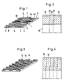
- the toothed belt 1 shown in FIG. 1 made of plastic or similar extrudable material, in the belt body 2 of which a tensile reinforcement insert 3 is embedded, is formed with a toothed belt side consisting of toothed ribs 4 and toothed grooves 5, which in the exemplary embodiment shown are in three strips side by side lying rows 6, 7 and 8 is divided by toothed rib sections.
- the narrower middle row 7 is offset in relation to the two adjacent rows 6 and 8 in the belt longitudinal direction or in the direction of the tooth pitch such that the toothed rib sections 4 a of the middle row 7 are at least partially to the side of the tooth grooves 5 of the two side rows 6 and 8.
- the toothed rib sections 4b of the rows 6 and 8 are laterally next to the tooth grooves of the row 7.
- the toothed rib sections 4a are offset by half the tooth pitch relative to the toothed rib sections 4b, so that the toothed rib sections each have the full cross section laterally next to the tooth grooves of the adjacent ones Row.
- the force transmission area of the belt toothing on the tooth flanks 9 is not reduced and is on both ends of the toothed rib sections 4a of the central strip 7 and also on the adjacent ends of the toothed rib sections 4b of the side strips 6 and 8 transverse to the toothed ribs 4 and toothed grooves 5 of the belt toothing guide surfaces 20 are formed, with which the toothed belt automatically leads on a suitably designed toothed pulley, so that the toothed pulley does not have any lateral flanges protruding from the toothed belt to secure the toothed belt against lateral runoff needs to show.
- the toothed belt can also have only two rows of toothed rib sections which are offset with respect to one another, in order to secure the toothed belt with the guide surfaces 20 of the two toothed rib rows facing one another in both lateral directions on a correspondingly designed toothed pulley against lateral runoff.
- Toothed rib rows 6, 7, 8 of the belt toothing from three adjacent and interconnected toothed pulley sections 11, 12, 13 which are twisted to match the belt toothing, so that the guide surfaces 20, for example, the central toothed rib row of the belt toothing with those of the toothed ribs of the two side toothed pulley sections formed stop surfaces 21 cooperate for lateral guidance of the toothed belt.
- the toothed rib rows 6, 7, 8 of the toothed belt 1 and the toothed pulley sections 11, 12, 13 of the toothed pulley 10 are advantageously matched in width in such a way that between the guide surfaces interacting for the lateral guidance 20 on the toothed belt teeth 4 on the one hand and the guide surfaces 21 on the toothed pulley teeth on the other hand there is a small predetermined distance in the belt transverse direction.
- the exemplary embodiment of the toothed belt shown in FIG. 3 has five narrow rows 14 of toothed rib sections, of which two adjacent rows are offset from one another by half the tooth pitch in the belt longitudinal direction.
- the rows 14 are preferably of the same width.
- the toothed pulley shown in FIG. 4 which matches the toothed belt of FIG. 3, consists of five toothed pulley sections 15 lying next to one another and rotated relative to one another.
- This design of the toothed belt and the associated toothed pulley has the additional advantage, in particular for large belt widths, that when the toothed belt rotates around Tooth pulley the air better and un hindered can escape from the tooth grooves receiving one tooth and thereby less noise is generated when the belt rotates around the toothed pulley.
Landscapes
- Engineering & Computer Science (AREA)
- General Engineering & Computer Science (AREA)
- Mechanical Engineering (AREA)
- Pulleys (AREA)
- Devices For Conveying Motion By Means Of Endless Flexible Members (AREA)
Abstract
Description
- Die Erfindung bezieht sich auf einen aus einem Zahnriemen und einer Zahnscheibe bestehenden Riementrieb gemäß dem Oberbegriff des Patentanspruchs.
- Normalerweise werden Zahnriemen beim Umlauf um eine Zahnscheibe zwischen zwei seitlichen Bordscheiben der Zahnscheibe seitlich geführt. Es gibt aber auch Zahnriementriebe, beispielsweise bei der Anwendung des Zahnriemens als Transportorgan in Transportanlagen, bei denen die Zahnscheibe nicht mit Bordscheiben seitlich über den Zahnriemen vorstehen kann. Hierfür ist z. B. aus der US-PS 2770 977 ein selbstführender Zahnriemen bekannt, bei dem entlang der Mittellinie der gezahnten Riemenseite eine strangförmige Führungsrippe angeordnet ist, die in eine passende Ringnut an der Mitte der gezahnten Umfangsfläche der Zahnscheibe eingreift, oder bei dem umgekehrt die gezahnte Riemenseite durch eine in Riemenlängsrichtung verlaufende Führungsnut in zwei Zahnrippenreihen geteilt ist und in die Nut eine Umfangsrippe der Zahnscheibe eingreift, um dadurch den Zahnriemen auch ohne Bordscheiben auf der Zahnscheibe seitlich zu führen. Nachteilig bei diesem bekannten Zahnriemen ist, daß die strangförmige Führungsrippe des Zahnriemens beim Umlauf um Zahnscheiben auf der Krümmungsinnenseite des Zahnriemens gestaucht werden muß, was trotz der bei dem bekannten Zahnriemen an der Führungsrippe vorgesehenen Einkerbungen die erwünschte weiche Biegbarkeit des Zahnriemens beeinträchtigt und zu einem ungünstigen Laufverhalten des Zahnriemens auf der Zahnscheibe führt. Insbesondere hat der bekannte Zahnriemen den Nachteil, daß durch die strangförmige Führungsrippe oder auch durch die längsverlaufende Führungsnut des Zahnriemens die Kraftübertragungsfläche an den Flanken der Zahnrippen verringert wird, so daß, um die gleiche Antriebsleistung wie ohne die Führungsrippe bzw. ohne die Führungsnut übertragen zu können, der Zahnriemen breiter gemacht werden muß, was den Riemen verteuert und wodurch der Umlauf des Zahnriemens um eine Zahnscheibe auch lauter wird.
- Die Erfindung hat zur Aufgabe, für einen Zahnriementrieb der eingangs genannten Art einen Zahnriemen zu schaffen, der sich ohne die Führungsrippe oder die Führungsnut der bekannten selbstführenden Zahnriemen auf einer Zahnscheibe gegen seitliches Ablaufen sichert und somit die Verringerung der Kraftübertragungsfläche durch die Führungsrippe bzw. Führungsnut vermeidet.
- Diese Aufgabe wird gemäß der Erfindung in erster Linie durch die Ausbildung des Riementriebes mit den im kennzeichnenden Teil des Patentanspruchs enthaltenen Merkmalen gelöst. Vorteilhafte Ausführungen des erfindungsgemäßen Riementriebes sind Gegenstand der Unteransprüche. Im folgenden werden anhand der Zeichnungen zwei Ausführungsbeispiele für den erfindungsgemäßen Riementrieb näher erläutert. Es zeigt
- Figur 1 ein erstes Beispiel der erfindungsgemäßen Ausbildung des Zahnriemens des Riementriebes;
- Figur 2 eine vorteilhafte Ausbildung einer zum Zahnriemen der Figur 1 passenden Zahnscheibe des Riementriebes;
- Figur 3 ein anderes Ausführungsbeispiel des Zahnriemens des Riementriebes;
- Figur 4 ein zu dem Zahnriemen der Figur 3 passendes Ausführungsbeispiel der Zahnscheibe.
- Der in der Figur 1 dargestellte Zahnriemen 1 aus Kunststoff oder dergleichen extrudierbarem Material, in dessen Riemenkörper 2 eine zugfeste Armierungseinlage 3 eingebettet ist, ist mit einer aus Zahnrippen 4 und Zahnnuten 5 bestehenden gezahnten Riemenseite ausgebildet, die bei dem dargestellten Ausführungsbeispiel in drei streifenartig nebeneinander liegende Reihen 6, 7 und 8 von Zahnrippenabschnitten geteilt ist. Während die Zahnrippenabschnitte der beiden seitlichen, breiteren Streifen 6 und 8 in Riemenquerrichtung fluchten, ist die schmalere mittlere Reihe 7 gegenüber den beiden benachbarten Reihen 6 und 8 in Riemenlängsrichtung bzw. in Richtung der Zahnteilung derart versetzt, daß die Zahnrippenabschnitte 4 a der mittleren Reihe 7 wenigstens teilweise seitlich neben den Zahnnuten 5 der beiden seitlichen Reihen 6 und 8 liegen. Gleichartig liegen die Zahnrippenabschnitte 4 b der Reihen 6 und 8 seitlich neben den Zahnnuten der Reihe 7. Vorteilhafterweise sind die Zahnrippenabschnitte 4a um die halbe Zahnteilung gegenüber den Zahnrippenabschnitten 4 b versetzt, so daß die Zahnrippenabschnitte jeweils mit dem vollen Querschnitt seitlich neben den Zahnnuten der benachbarten Reihe liegen. Durch die Aufteilung der Zahnrippen der Riemenverzahnung in gegeneinander versetzte Reihen von Zahnrippenabschnitten wird die Kraftübertragungsfläche der Riemenverzahnung an den Zahnflanken 9 nicht verringert und werden an beiden Enden der Zahnrippenabschnitte 4 a des mittleren Streifens 7 wie auch an den benachbarten Enden der Zahnrippenabschnitte 4 b der seitlichen Streifen 6 und 8 quer zu den Zahnrippen 4 und Zahnnuten 5 der Riemenverzahnung stehende Führungsflächen 20 gebildet, mit denen sich der Zahnriemen selbsttätig auf einer entsprechend ausgebildeten Zahnscheibe führt, so daß die Zahnscheibe keine seitlichen, über den Zahnriemen vorstehende Bordscheiben zum Sichern des Zahnriemens gegen seitliches Ablaufen aufzuweisen braucht. Wie die Figur 1 erkennen läßt, kann der Zahnriemen auch nur zwei gegeneinander versetzte Reihen von Zahnrippenabschnitten aufweisen, um den Zahnriemen mit den aneinander zugekehrten Führungsflächen 20 der beiden Zahnrippenreihen in beiden Seitenrichtungen auf einer entsprechend ausgebildeten Zahnscheibe gegen seitliches Ablaufen zu sichern. Die in Figur 2 dargestellte, zu dem Zahnriemen der Figur 1 passende Zahnscheibe 10 besteht entsprechend der Anzahl der Zahnrippenreihen 6, 7, 8 der Riemenverzahnung aus drei nebeneinander liegenden und miteinander verbundenen Zahnscheibenabschnitten 11, 12, 13 die passend zur Riemenverzahnung gegeneinander verdreht sind, so daß die Führungsflächen 20 zum Beispiel der mittleren Zahnrippenreihe der Riemenverzahnung mit den von den Zahnrippen der beiden seitlichen Zahnscheibenabschnitte gebildeten Anschlagflächen 21 zur Seitenführung des Zahnriemens zusammenwirken.
- Bei der Ausbildung des Zahnriemens mit drei oder mehr Reihen von Zahnrippenabschnitten sind vorteilhafterweise die Zahnrippenreihen 6, 7, 8 des Zahnriemens 1 und die Zahnscheibenabschnitte 11, 12, 13 der Zahnscheibe 10 in der Breite derart aufeinander abgestimmt, daß zwischen den für die Seitenführung zusammenwirkenden Führungsflächen 20 an den Zahnriemenzähnen 4 einerseits und den Führungsflächen 21 an den Zahnscheibenzähnen andererseits ein kleiner vorbestimmter Abstand in Riemenquerrichtung besteht. Dadurch wird sichergestellt, daß die Riemenzähne und Zahnscheibenzähne sich nicht an den Führungsflächen 20 und 21 verkeilen, sondern ungehindert so weit ineinandergreifen können, daß sich der Zahnriemen bestimmungsgemäß mit der Kopffläche seiner Zähne oder mit der Grundfläche seiner Zahnlücken auf die korrespondierenden Flächen der Zahnscheibenverzahnung auflegt.
- Das in Figur 3 dargestellte Ausführungsbeispiel des Zahnriemens hat fünf schmale Reihen 14 von Zahnrippenabschnitten, von denen jeweils zwei benachbarte Reihen um die halbe Zahnteilung in Riemenlängsrichtung gegeneinander versetzt sind. Vorzugsweise haben die Reihen 14 die gleiche Breite. Dementsprechend besteht die in Figur 4 dargestellte, zu dem Zahnriemen der Figur 3 passende Zahnscheibe aus fünf nebeneinander liegenden und gegeneinander verdrehten Zahnscheibenabschnitten 15. Diese Ausführung des Zahnriemens und der zugehörigen Zahnscheibe hat insbesondere für große Riemenbreiten den zusätzlichen Vorteil, daß beim Umlaufen des Zahnriemens um die Zahnscheibe die Luft besser und un gehinderter aus den jeweils einen Zahn aufnehmenden Zahnnuten entweichen kann und dadurch beim Riemenumlauf um die Zahnscheibe weniger Geräusch entsteht.
Claims (3)
Priority Applications (1)
| Application Number | Priority Date | Filing Date | Title |
|---|---|---|---|
| AT90100620T ATE103042T1 (de) | 1989-03-25 | 1990-01-12 | Riementrieb bestehend aus einem zahnriemen und einer zahnscheibe. |
Applications Claiming Priority (2)
| Application Number | Priority Date | Filing Date | Title |
|---|---|---|---|
| DE3909950 | 1989-03-25 | ||
| DE3909950A DE3909950C2 (de) | 1989-03-25 | 1989-03-25 | Riementrieb bestehend aus einem Zahnriemen und einer Zahnscheibe |
Publications (3)
| Publication Number | Publication Date |
|---|---|
| EP0389742A2 true EP0389742A2 (de) | 1990-10-03 |
| EP0389742A3 EP0389742A3 (de) | 1991-12-27 |
| EP0389742B1 EP0389742B1 (de) | 1994-03-16 |
Family
ID=6377268
Family Applications (1)
| Application Number | Title | Priority Date | Filing Date |
|---|---|---|---|
| EP90100620A Expired - Lifetime EP0389742B1 (de) | 1989-03-25 | 1990-01-12 | Riementrieb bestehend aus einem Zahnriemen und einer Zahnscheibe |
Country Status (7)
| Country | Link |
|---|---|
| US (1) | US5006096A (de) |
| EP (1) | EP0389742B1 (de) |
| JP (1) | JP2655928B2 (de) |
| AT (1) | ATE103042T1 (de) |
| CA (1) | CA2012942C (de) |
| DE (2) | DE3909950C2 (de) |
| ES (1) | ES2049849T3 (de) |
Cited By (1)
| Publication number | Priority date | Publication date | Assignee | Title |
|---|---|---|---|---|
| IT201900005650A1 (it) * | 2019-04-12 | 2020-10-12 | A Zeta Gomma S P A | Cinghia dentellata di trasporto. |
Families Citing this family (16)
| Publication number | Priority date | Publication date | Assignee | Title |
|---|---|---|---|---|
| US5427580A (en) * | 1992-05-19 | 1995-06-27 | Borg-Warner Automotive, Inc. | Phased chain assemblies |
| DE4341572C1 (de) * | 1993-12-07 | 1995-06-22 | Univ Dresden Tech | Zahnriemengetriebe |
| DE19941833B4 (de) * | 1999-09-02 | 2005-02-24 | Hell Gravure Systems Gmbh | Riemenantrieb zur Erzeugung einer gleichförmigen Drehbewegung |
| US6123039A (en) * | 1999-12-07 | 2000-09-26 | Yugen Kaisha Niiken Kogyosho | Endless-belt type walking presser foot |
| IL141094A0 (en) * | 2001-01-25 | 2002-02-10 | Ran Siman Tov | Continuous variable transmission |
| DE10347986A1 (de) * | 2003-10-16 | 2005-05-12 | Zf Lenksysteme Gmbh | Zahnriemenrad und damit ausgestatteter Zahnriemenantrieb |
| US20050113199A1 (en) * | 2003-11-26 | 2005-05-26 | Brecoflex Co., L.L.C. | Toothed belt with tooth reinforcements |
| US20050159262A1 (en) * | 2004-01-21 | 2005-07-21 | Brecoflex Co., L.L.C. | Timing belt with wave glide surface |
| JP2007210362A (ja) * | 2006-02-07 | 2007-08-23 | Aisin Seiki Co Ltd | サンルーフ装置 |
| JP5386116B2 (ja) * | 2008-06-20 | 2014-01-15 | ボーグワーナー インコーポレーテッド | サイレントチェーン |
| JP4942722B2 (ja) * | 2008-10-16 | 2012-05-30 | 株式会社椿本チエイン | 歯付ベルト用プーリ |
| DE202016001776U1 (de) * | 2016-03-18 | 2017-06-21 | Gebr. Bode Gmbh & Co. Kg | Zahnriemenantrieb mit Kraftmitnehmern |
| US10578202B2 (en) * | 2017-06-13 | 2020-03-03 | Abb Schweiz Ag | Sprocket for a synchronous drive belt system |
| DE102018107642B4 (de) * | 2018-03-29 | 2019-12-24 | Arntz Beteiligungs Gmbh & Co. Kg | Riementrieb |
| DE102020106251A1 (de) | 2020-03-09 | 2021-09-09 | Arntz Beteiligungs Gmbh & Co. Kg | Zahnriemen und Riementrieb diesen aufweisend |
| WO2024050008A1 (en) * | 2022-08-31 | 2024-03-07 | Gates Corporation | Self-aligning power transmission belts and systems incorporating the same |
Family Cites Families (15)
| Publication number | Priority date | Publication date | Assignee | Title |
|---|---|---|---|---|
| US2770977A (en) * | 1953-11-27 | 1956-11-20 | Continental Gummi Werke Ag | Belt transmissions |
| DE1747652U (de) * | 1956-06-22 | 1957-06-27 | Wilhelm Herm Mueller & Co K G | Zahnriemen aus kunststoff. |
| US3338107A (en) * | 1965-02-15 | 1967-08-29 | Kiekhaefer Corp | Positive drive system |
| US3948110A (en) * | 1974-10-18 | 1976-04-06 | Outboard Marine Corporation | Endless cleated track |
| JPS5570642U (de) * | 1978-11-09 | 1980-05-15 | ||
| US4449958A (en) * | 1981-09-24 | 1984-05-22 | Conrad Rene A | Positive tracking pulley and belt construction |
| FI64445C (fi) * | 1982-03-10 | 1983-11-10 | Tampella Oy Ab | Kuggremdriven larmdaempad kraftoeverfoeringsanordning |
| JPS58214053A (ja) * | 1982-06-08 | 1983-12-13 | Ito Kogyo Kk | 歯付ベルト伝動装置 |
| US4571224A (en) * | 1982-07-27 | 1986-02-18 | Unitta Co., Ltd. | Belt drive system |
| DD215833A1 (de) * | 1982-12-28 | 1984-11-21 | Robotron Rechen Und Schreibtec | Zugmittelgetriebe fuer zahnriemen |
| US4553951A (en) * | 1983-06-02 | 1985-11-19 | The Gerber Scientific Instrument Company | Non-slip pulley and belt drive |
| JPS60157551A (ja) * | 1984-01-27 | 1985-08-17 | Fujitsu Ltd | 歯付ベルト伝動のバツクラツシ除去方法 |
| JPS62176539U (de) * | 1986-04-28 | 1987-11-10 | ||
| JPH077642Y2 (ja) * | 1987-12-16 | 1995-02-22 | 三菱自動車工業株式会社 | タイミングベルト及びスプロケットの歯型構造 |
| DE8903744U1 (de) * | 1989-03-25 | 1989-06-22 | Breco Kunststoffverarbeitungs-Gmbh & Co Kg, 4952 Porta Westfalica | Riementrieb bestehend aus einem Zahnriemen und einer Zahnscheibe |
-
1989
- 1989-03-25 DE DE3909950A patent/DE3909950C2/de not_active Expired - Fee Related
-
1990
- 1990-01-12 DE DE90100620T patent/DE59004967D1/de not_active Expired - Fee Related
- 1990-01-12 EP EP90100620A patent/EP0389742B1/de not_active Expired - Lifetime
- 1990-01-12 ES ES90100620T patent/ES2049849T3/es not_active Expired - Lifetime
- 1990-01-12 AT AT90100620T patent/ATE103042T1/de not_active IP Right Cessation
- 1990-03-14 US US07/494,179 patent/US5006096A/en not_active Expired - Lifetime
- 1990-03-23 CA CA002012942A patent/CA2012942C/en not_active Expired - Lifetime
- 1990-03-23 JP JP2072266A patent/JP2655928B2/ja not_active Expired - Lifetime
Cited By (1)
| Publication number | Priority date | Publication date | Assignee | Title |
|---|---|---|---|---|
| IT201900005650A1 (it) * | 2019-04-12 | 2020-10-12 | A Zeta Gomma S P A | Cinghia dentellata di trasporto. |
Also Published As
| Publication number | Publication date |
|---|---|
| EP0389742B1 (de) | 1994-03-16 |
| JP2655928B2 (ja) | 1997-09-24 |
| ATE103042T1 (de) | 1994-04-15 |
| DE59004967D1 (de) | 1994-04-21 |
| DE3909950A1 (de) | 1990-09-27 |
| JPH02283945A (ja) | 1990-11-21 |
| CA2012942A1 (en) | 1990-09-25 |
| ES2049849T3 (es) | 1994-05-01 |
| DE3909950C2 (de) | 1993-12-23 |
| EP0389742A3 (de) | 1991-12-27 |
| CA2012942C (en) | 1993-08-31 |
| US5006096A (en) | 1991-04-09 |
Similar Documents
| Publication | Publication Date | Title |
|---|---|---|
| EP0389742B1 (de) | Riementrieb bestehend aus einem Zahnriemen und einer Zahnscheibe | |
| EP0389741B1 (de) | Riementrieb bestehend aus einem Zahnriemen und einer Zahnscheibe | |
| EP0601279B1 (de) | Zahn-und Keilriemeneinrichtung für Laufbänder | |
| DE2928828C2 (de) | Rinnenförmige Kantenschutzleiste | |
| DE69006520T2 (de) | Getriebe mit einem Antriebsriemen und Kegelscheiben. | |
| DE69402317T2 (de) | Orientierer | |
| DE2624424B2 (de) | Zahnriemen | |
| DE3607524C2 (de) | ||
| EP0153558A2 (de) | Bauteilsatz zum Anfertigen einer Lamelle eines Lamellenstores | |
| DE3510384C2 (de) | ||
| DE3121662C2 (de) | Getriebe, insbesondere Planetengetriebe | |
| DE2738426A1 (de) | Gezahnter endlosriemen | |
| DE4226744A1 (de) | Faser zur Bewehrung von Beton oder dergleichen aus Draht oder Flachband und Einrichtung zum Herstellen solcher Fasern | |
| DE4243336C2 (de) | Flachkabel | |
| DE69611899T2 (de) | Geräuscharmer Riemen für stufenloses Getriebe | |
| DE2242679C2 (de) | Einheitliches flexibles Druckband für Druckvorrichtungen | |
| EP0079492A1 (de) | Schallschutzvorrichtung | |
| EP0505919B1 (de) | Zahnriementrieb | |
| DE2748862A1 (de) | Nagelstreifen | |
| DE8903744U1 (de) | Riementrieb bestehend aus einem Zahnriemen und einer Zahnscheibe | |
| DE3209300A1 (de) | Furnierkante | |
| DE3539894A1 (de) | Verkleidung fuer bauwerke | |
| EP0158064A2 (de) | Dichtung für eine Verdrängermaschine für kompressible Medien | |
| EP0571654B1 (de) | Einteilige elastische Blende zur Abdichtung eines Schlitzes in einem Schiebesteller | |
| DE888974C (de) | Abstuetzung bzw. Fuehrung von Foerderbaendern an Eckfuehrungsstellen |
Legal Events
| Date | Code | Title | Description |
|---|---|---|---|
| PUAI | Public reference made under article 153(3) epc to a published international application that has entered the european phase |
Free format text: ORIGINAL CODE: 0009012 |
|
| AK | Designated contracting states |
Kind code of ref document: A2 Designated state(s): AT BE CH DE DK ES FR GB IT LI LU NL SE |
|
| PUAL | Search report despatched |
Free format text: ORIGINAL CODE: 0009013 |
|
| AK | Designated contracting states |
Kind code of ref document: A3 Designated state(s): AT BE CH DE DK ES FR GB IT LI LU NL SE |
|
| 17P | Request for examination filed |
Effective date: 19920110 |
|
| 17Q | First examination report despatched |
Effective date: 19930709 |
|
| GRAA | (expected) grant |
Free format text: ORIGINAL CODE: 0009210 |
|
| AK | Designated contracting states |
Kind code of ref document: B1 Designated state(s): AT BE CH DE DK ES FR GB IT LI LU NL SE |
|
| PG25 | Lapsed in a contracting state [announced via postgrant information from national office to epo] |
Ref country code: DK Effective date: 19940316 Ref country code: SE Free format text: THE PATENT HAS BEEN ANNULLED BY A DECISION OF A NATIONAL AUTHORITY Effective date: 19940316 |
|
| REF | Corresponds to: |
Ref document number: 103042 Country of ref document: AT Date of ref document: 19940415 Kind code of ref document: T |
|
| REF | Corresponds to: |
Ref document number: 59004967 Country of ref document: DE Date of ref document: 19940421 |
|
| REG | Reference to a national code |
Ref country code: ES Ref legal event code: FG2A Ref document number: 2049849 Country of ref document: ES Kind code of ref document: T3 |
|
| ET | Fr: translation filed | ||
| ITF | It: translation for a ep patent filed | ||
| GBT | Gb: translation of ep patent filed (gb section 77(6)(a)/1977) |
Effective date: 19940621 |
|
| PLBE | No opposition filed within time limit |
Free format text: ORIGINAL CODE: 0009261 |
|
| STAA | Information on the status of an ep patent application or granted ep patent |
Free format text: STATUS: NO OPPOSITION FILED WITHIN TIME LIMIT |
|
| PG25 | Lapsed in a contracting state [announced via postgrant information from national office to epo] |
Ref country code: LU Free format text: LAPSE BECAUSE OF NON-PAYMENT OF DUE FEES Effective date: 19950131 |
|
| 26N | No opposition filed | ||
| REG | Reference to a national code |
Ref country code: GB Ref legal event code: IF02 |
|
| PGFP | Annual fee paid to national office [announced via postgrant information from national office to epo] |
Ref country code: ES Payment date: 20080130 Year of fee payment: 19 Ref country code: CH Payment date: 20080115 Year of fee payment: 19 |
|
| PGFP | Annual fee paid to national office [announced via postgrant information from national office to epo] |
Ref country code: NL Payment date: 20080115 Year of fee payment: 19 Ref country code: IT Payment date: 20080125 Year of fee payment: 19 Ref country code: GB Payment date: 20080124 Year of fee payment: 19 Ref country code: DE Payment date: 20080131 Year of fee payment: 19 |
|
| PGFP | Annual fee paid to national office [announced via postgrant information from national office to epo] |
Ref country code: AT Payment date: 20080116 Year of fee payment: 19 |
|
| PGFP | Annual fee paid to national office [announced via postgrant information from national office to epo] |
Ref country code: FR Payment date: 20080111 Year of fee payment: 19 |
|
| PGFP | Annual fee paid to national office [announced via postgrant information from national office to epo] |
Ref country code: BE Payment date: 20080304 Year of fee payment: 19 |
|
| REG | Reference to a national code |
Ref country code: CH Ref legal event code: PL |
|
| GBPC | Gb: european patent ceased through non-payment of renewal fee |
Effective date: 20090112 |
|
| NLV4 | Nl: lapsed or anulled due to non-payment of the annual fee |
Effective date: 20090801 |
|
| PG25 | Lapsed in a contracting state [announced via postgrant information from national office to epo] |
Ref country code: AT Free format text: LAPSE BECAUSE OF NON-PAYMENT OF DUE FEES Effective date: 20090112 Ref country code: DE Free format text: LAPSE BECAUSE OF NON-PAYMENT OF DUE FEES Effective date: 20090801 Ref country code: CH Free format text: LAPSE BECAUSE OF NON-PAYMENT OF DUE FEES Effective date: 20090131 Ref country code: LI Free format text: LAPSE BECAUSE OF NON-PAYMENT OF DUE FEES Effective date: 20090131 |
|
| REG | Reference to a national code |
Ref country code: FR Ref legal event code: ST Effective date: 20091030 |
|
| PG25 | Lapsed in a contracting state [announced via postgrant information from national office to epo] |
Ref country code: NL Free format text: LAPSE BECAUSE OF NON-PAYMENT OF DUE FEES Effective date: 20090801 Ref country code: GB Free format text: LAPSE BECAUSE OF NON-PAYMENT OF DUE FEES Effective date: 20090112 |
|
| PG25 | Lapsed in a contracting state [announced via postgrant information from national office to epo] |
Ref country code: BE Free format text: LAPSE BECAUSE OF NON-PAYMENT OF DUE FEES Effective date: 20090131 |
|
| REG | Reference to a national code |
Ref country code: ES Ref legal event code: FD2A Effective date: 20090113 |
|
| PG25 | Lapsed in a contracting state [announced via postgrant information from national office to epo] |
Ref country code: ES Free format text: LAPSE BECAUSE OF NON-PAYMENT OF DUE FEES Effective date: 20090113 Ref country code: FR Free format text: LAPSE BECAUSE OF NON-PAYMENT OF DUE FEES Effective date: 20090202 |
|
| PG25 | Lapsed in a contracting state [announced via postgrant information from national office to epo] |
Ref country code: IT Free format text: LAPSE BECAUSE OF NON-PAYMENT OF DUE FEES Effective date: 20090112 |