EP0390381A2 - Gruppe von Trägheits-Aufpralldämpfern - Google Patents
Gruppe von Trägheits-Aufpralldämpfern Download PDFInfo
- Publication number
- EP0390381A2 EP0390381A2 EP90302835A EP90302835A EP0390381A2 EP 0390381 A2 EP0390381 A2 EP 0390381A2 EP 90302835 A EP90302835 A EP 90302835A EP 90302835 A EP90302835 A EP 90302835A EP 0390381 A2 EP0390381 A2 EP 0390381A2
- Authority
- EP
- European Patent Office
- Prior art keywords
- masses
- containers
- array
- dispersible
- array according
- Prior art date
- Legal status (The legal status is an assumption and is not a legal conclusion. Google has not performed a legal analysis and makes no representation as to the accuracy of the status listed.)
- Granted
Links
- 230000004888 barrier function Effects 0.000 title claims abstract description 93
- 239000004576 sand Substances 0.000 claims abstract description 41
- 239000000463 material Substances 0.000 claims abstract description 15
- XLYOFNOQVPJJNP-UHFFFAOYSA-N water Substances O XLYOFNOQVPJJNP-UHFFFAOYSA-N 0.000 claims description 7
- 230000002093 peripheral effect Effects 0.000 abstract description 3
- 230000000284 resting effect Effects 0.000 abstract 1
- 230000003116 impacting effect Effects 0.000 description 12
- 230000005484 gravity Effects 0.000 description 11
- UWSMKYBKUPAEJQ-UHFFFAOYSA-N 5-Chloro-2-(3,5-di-tert-butyl-2-hydroxyphenyl)-2H-benzotriazole Chemical compound CC(C)(C)C1=CC(C(C)(C)C)=CC(N2N=C3C=C(Cl)C=CC3=N2)=C1O UWSMKYBKUPAEJQ-UHFFFAOYSA-N 0.000 description 4
- 238000003491 array Methods 0.000 description 4
- XITRBUPOXXBIJN-UHFFFAOYSA-N bis(2,2,6,6-tetramethylpiperidin-4-yl) decanedioate Chemical compound C1C(C)(C)NC(C)(C)CC1OC(=O)CCCCCCCCC(=O)OC1CC(C)(C)NC(C)(C)C1 XITRBUPOXXBIJN-UHFFFAOYSA-N 0.000 description 4
- 230000001133 acceleration Effects 0.000 description 3
- 238000010276 construction Methods 0.000 description 3
- 239000007787 solid Substances 0.000 description 3
- 239000003381 stabilizer Substances 0.000 description 3
- 238000010998 test method Methods 0.000 description 3
- 239000004088 foaming agent Substances 0.000 description 2
- 229920001903 high density polyethylene Polymers 0.000 description 2
- 239000004700 high-density polyethylene Substances 0.000 description 2
- 239000011347 resin Substances 0.000 description 2
- 229920005989 resin Polymers 0.000 description 2
- 239000011800 void material Substances 0.000 description 2
- 239000012963 UV stabilizer Substances 0.000 description 1
- 238000013459 approach Methods 0.000 description 1
- XOZUGNYVDXMRKW-AATRIKPKSA-N azodicarbonamide Chemical compound NC(=O)\N=N\C(N)=O XOZUGNYVDXMRKW-AATRIKPKSA-N 0.000 description 1
- 230000000981 bystander Effects 0.000 description 1
- 239000011521 glass Substances 0.000 description 1
- 229920001684 low density polyethylene Polymers 0.000 description 1
- 239000004702 low-density polyethylene Substances 0.000 description 1
- 238000004519 manufacturing process Methods 0.000 description 1
- 229920001179 medium density polyethylene Polymers 0.000 description 1
- 239000004701 medium-density polyethylene Substances 0.000 description 1
- 238000000034 method Methods 0.000 description 1
- 239000000203 mixture Substances 0.000 description 1
- 238000012986 modification Methods 0.000 description 1
- 230000004048 modification Effects 0.000 description 1
- 230000000704 physical effect Effects 0.000 description 1
- 239000000326 ultraviolet stabilizing agent Substances 0.000 description 1
Images


Classifications
-
- E—FIXED CONSTRUCTIONS
- E01—CONSTRUCTION OF ROADS, RAILWAYS, OR BRIDGES
- E01F—ADDITIONAL WORK, SUCH AS EQUIPPING ROADS OR THE CONSTRUCTION OF PLATFORMS, HELICOPTER LANDING STAGES, SIGNS, SNOW FENCES, OR THE LIKE
- E01F15/00—Safety arrangements for slowing, redirecting or stopping errant vehicles, e.g. guard posts or bollards; Arrangements for reducing damage to roadside structures due to vehicular impact
- E01F15/14—Safety arrangements for slowing, redirecting or stopping errant vehicles, e.g. guard posts or bollards; Arrangements for reducing damage to roadside structures due to vehicular impact specially adapted for local protection, e.g. for bridge piers, for traffic islands
- E01F15/145—Means for vehicle stopping using impact energy absorbers
- E01F15/146—Means for vehicle stopping using impact energy absorbers fixed arrangements
Definitions
- This invention relates to an improved array of inertial barriers of the type used alongside a roadway to decelerate a vehicle that has left the roadway.
- Inertial highway barriers have been used for some time to prevent vehicles from striking an obstacle such as a bridge pier or the like at full velocity.
- An inertial barrier relies on the mass of the barrier to decelerate the vehicle.
- a dispersible material such as sand is enclosed in a frangible container. When the vehicle strikes the container, the momentum of the impacting vehicle is dissipated in accelerating the sand.
- the mass of sand is elevated above the roadway on a platform in an attempt to match the heights of the centers of gravity of the barrier and the impacting vehicle. In this way, the tendency of the impacting vehicle to be accelerated vertically (either up or down) by the barrier is minimized.
- Later approaches have used other structures to elevate the center of gravity of the dispersible mass.
- U.S. Patent 4,073,482 discloses barriers having sand in a wine glass shape.
- U.S. Patent 4,289,419 discloses an inertial barrier system wherein a central void is provided in the lower part of the barriers.
- U.S. Patents 4,688,766 and 4,557,466 disclose inertial barriers wherein an insert is used to elevate the center of gravity of the lighter weight barriers.
- the more massive barriers include a substantially monolithic block of dispersible material.
- This configuration causes the mass per unit of height of the barrier to be relatively large. For this reason, a mismatch of only a few inches between the elevations of the centers of gravity of the barrier and the impacting vehicle can result in undesirably large vertical accelerations being imparted to the vehicle.
- This configuration can represent an unnecessary hazard to an impacting vehicle if the sand is wet and frozen.
- the monolithic block of sand is no longer easily dispersible, and it can cause unacceptably large decelerations to the vehicle.
- unacceptably large blocks of frozen sand may be accelerated by the vehicle, and these accelerated blocks may present hazards to bystanders.
- an array of inertial barriers positioned on a support surface alongside a vehicle roadway, said array comprising: a plurality of frangible containers arranged along an axis, each of said containers comprising an outer wall and a lower portion; a plurality of inner cores, each disposed in a respective one of the containers and defining an annular space between the core and the respective outer wall, said annular space defining an average inner diameter and an average outer diameter, wherein the average inner diameter is at least about 25% of the average outer diameter; a plurality of masses of dispersible material, each disposed in a respective one of the annular spaces such that each of the masses in the entire array of inertial barriers is substantially annular in shape with no more than about 10% of any of the masses in the array extending in an uninterrupted disc across the respective container.
- the invention provides an inertial barrier array that provides reduced vertical accelerations to an impacting vehicle, in spite of variations in the height of the center of gravity of the impacting vehicle.
- the invention provides an inertial barrier array which reduces or eliminates solid masses or discs of dispersible material extending completely across the barriers of the array.
- the invention also provides an improved inertial barrier array in which each of the barriers of the array has improved water drainage characteristics.
- the barriers are graduated in mass, with less massive barriers situated at one end of the axis.
- the average inner diameter is at least about 40% of the average outer diameter for each of the annular spaces, and drainage holes are provided in the frangible containers to drain water from the dispersible masses.
- each of the inner cores passes completely through the respective dispersible mass from top to bottom such that each of the dispersible masses is annular in configuration.
- the preferred embodiments of this invention entirely eliminate solid discs of sand extending completely across the container. This reduces vertical accelerations imparted to an impacting vehicle over a wide range of vehicle heights. In addition, it improves the drainage of water from the sand, and it reduces the likelihood that a large block of sand will be accelerated as a monolithic mass during an impact.
- an array of inertial barriers positioned on a support surface alongside a vehicle roadway, said array comprising: an array of frangible containers arranged along an axis, each of said containers comprising an outer wall and a lower portion, said containers comprising a plurality of shorter containers at a front end of the axis and at least one taller container at a rear end of the axis; a plurality of inner cores, each disposed in a respective one of the containers and defining an annular space between the core and the respective outer wall, said annular space defining an average inner diameter and an average outer diameter, wherein the average inner diameter is at least about 25% of the average outer diameter, said inner cores comprising shorter inner cores supported on the outer walls of at least some of the shorter containers and at least one longer inner core supported on the lower portion of the at least one taller container; a plurality of masses of dispersible material, each disposed in a respective one of the annular spaces such that each of the masses in the entire array
- Figures 4-7 show two separate arrays of inertial highway barriers that embody the present invention. Before turning to these figures, details of construction of the individual barriers will be described in conjunction with Figures 1-3e.
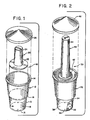
- Figure 1 shows an exploded perspective view of a first inertial barrier 10.
- This barrier 10 includes a container 12 which includes a peripheral sidewall 13 which terminates at its upper end in an annular lip 14 and at its lower end in a bottom panel 15.
- the bottom panel 15 is provided with an array of drain holes 16, and the sidewall 13 defines a shoulder 18 at an intermediate position.
- the barrier 10 also includes an inner core or insert 20 that includes an annular flange 22 and a cylindrical or frusto-conical upper section 24.
- the flange 22 is positioned to rest on the shoulder 18 to support the insert 20 in place, and the flange 22 has sufficient structural rigidity to support a mass of dispersible material such as sand in the annular space between the upper section 24 and the sidewall 13.
- the barrier 10 includes a lid 26 which is designed to engage the lip 14 to securely hold the lid 26 in place.
- FIG 2 shows an exploded perspective view of a second barrier 30 which is generally similar to the barrier 10 described above.
- the barrier 30 includes a container 32 having a sidewall 34, a bottom surface 36, and drain holes 38.
- the container 32 is similar to the container 12, but is somewhat higher in overall height.
- the barrier 30 includes an insert 40 having an annular flange 42 and a frusto-conical upper section 44.
- the insert 40 is designed to rest on the bottom surface 36 and to create an annular space between the upper section 44 and the sidewall 34. This annular space is intended to receive a dispersible material such as sand when the barrier is fully assembled.
- the barrier 30 includes a lid 46 which is similar to the lid 26 described above, but may be more steeply angled as shown in Figure 2.
- the container 32 is shown as defining a flange in the side wall, but this feature may readily be detected if desired.
- the arrays of barriers shown in Figures 4-7 include a number of separate barriers.
- the array of Figures 4 and 5 includes barriers of five different masses; Figures 3a-3e provide cross-sectional views of these five different barriers.
- the barriers of Figures 3a, 3b and 3c are identical in structure with the barrier 10 shown in Figure 1, but each contains a different quantity of sand S.
- the barriers of Figures 3a, 3b and 3c have a sand mass of 200, 400 and 700 pounds, respectively.
- the annular space occupied by the sand defines an average inner diameter D I and an average outer diameter D O .
- the average inner diameter D I is at least about 20% of the average outer diameter D O , and most preferably the average inner diameter D I is at least 40% of the average outer diameter D O .
- Figure 3d shows a more massive barrier 50 having a weight of 1400 pounds.
- the barrier 50 is made up of a mix of the parts described above.
- the container is the shorter container 12 of Figure 1 while the insert 40 and the lid 46 are as shown in Figure 2. Because the lid 46 is more steeply angled, the container 12 can be used with the insert 40.
- Figure 3e shows the distribution of sand in the barrier 30 of Figure 2.
- the centers of gravity of all five of the barriers are at approximately the same height (within a range of about five inches), and this height matches that of the center of gravity of the average impacting vehicle for which the barriers are designed.
- Figures 3a-3e illustrate a number of important features of the inertial barriers 10, 30, 50.
- the insert 20, 40 extends completely through the mass of sand S such that the mass of sand S has an annular configuration at any cross-section. It is not essential in all embodiments of this invention that the insert 20, 40 pass completely through the mass of sand S, but in general it is preferred that less than 10% of the mass of sand S be disposed in an uninterrupted disc passing completely across the container 12, 32.
- a second important advantage is that because the sand is disposed completely in an annular space, there is more of a tendency for the sand to be broken into small pieces during an impact.
- the containers 12, 32 are frangible and are designed to break apart during an impact. In the event the sand is wet and frozen, a monolithic block of sand can result in undesirably large blocks of frozen sand being accelerated away from the impact.
- the configurations of Figures 3a-3e provide a central void in the mass of sand in each case. This promotes break-up of any frozen sand into manageable sizes during an impact.
- FIG. 3a-3e Yet a third advantage is improved drainage provided by the configurations of Figures 3a-3e. These configurations result in increased vertical height of sand for given mass as compared to a monolithic body of sand. This increased vertical height increases the pressure of water at the bottom of the column of sand, and thereby increases the efficiency with which water is drained via the drainage holes 16, 38. In this regard, it is important that the fit between the insert 20 and the shoulder 18 and the fit between the insert 40 and the bottom surface 36 be sufficiently loose as to allow adequate drainage.
- each of the barriers in the array includes a respective mass of sand S that is annular in shape, with the respective insert 20, 40 extending completely from the top to the bottom through the mass of sand.
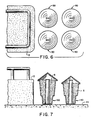
- Figures 6 and 7 show one smaller array made up of four inertial barriers 30, 50. Once again, the barriers are progressively heavier in weight near the obstacle O, and are freely supported on a support surface SS.
- each barrier may have a distinctive container, insert and lid if desired.
- the lids 26, 46 can be rotationally molded of a high, low, or medium density polyethylene resin.
- the lid should preferably have the properties set out in Table I.
- the container 12, 32 can also be rotationally molded of a high density polyethylene (H.D.P.E.) using a resin such as that available under the tradename Chemplex 5305 or Allied 7002.
- H.D.P.E. high density polyethylene
- the materials listed in Table II can be used in a three-layer system having a center layer of foamed H.D.P.E. and inner and outer layers of nonformed H.D.P.E..
- the various quantities of H.D.P.E., UV Stabilizers and foaming agent are dry blended for a minimum of 20 minutes using a sigma blade mixer.
- the resulting three layer container should preferably have the physical characteristics set out in Table III.
- a three-layer wall is not required for the container 12, 32, and it may be preferable in some applications to use two layers: a foamed inner layer approximately 3/16 ⁇ in thickness and an unfoamed outer layer approximately 1/16 ⁇ in thickness.
- the insert 20, 40 can also be rotationally molded of H.D.P.E. such as that described above.
- the H.D.P.E. is preferably combined with an ultraviolet stabilizer such as .45 grams per pound of TINUVIN 770 and TINUVIN 327.
- the resulting insert preferably has the physical properties set out in Table IV.
- Stabilizer .64 gm/lb TINUVIN 770 +/- .05 gm/lb. .64 gm/lb TINUVIN 327 +/- .05 gm/lb.
- Middle Layer 9 +/- .25 lb. H.D.P.E.
- Foaming Agent 3.7 gm/lb CELOGEN AZ-130 U.V.
- Stabilizer .50 gm/lb TINUVIN 770 +/- .05 gm/lb. .50 gm/lb TINUVIN 327 +/- .05 gm/lb.
- Inner Layer 5 1/2 +/- lb. H.D.P.E. U.V.
- Stabilizer .64 gm/lb TINUVIN 770 +/- .05 gm/lb. .64 gm/lb TINUVIN 327 +/- .05 gm/lb. TABLE III Property (Units) Test Method Value Tensile Strength (PSI) ASTM-D-638 1400 +/- 200 Elongation (%) ASTM-D-638 200 min. Low Temperature Impact Resistance ARM Falling Dart Test (5 lb dart with 1/2" radius nose, 2 ft.
Landscapes
- Engineering & Computer Science (AREA)
- Architecture (AREA)
- Civil Engineering (AREA)
- Structural Engineering (AREA)
- Refuge Islands, Traffic Blockers, Or Guard Fence (AREA)
- Aiming, Guidance, Guns With A Light Source, Armor, Camouflage, And Targets (AREA)
- Inorganic Insulating Materials (AREA)
- Polishing Bodies And Polishing Tools (AREA)
- Vibration Dampers (AREA)
- Chair Legs, Seat Parts, And Backrests (AREA)
- Financial Or Insurance-Related Operations Such As Payment And Settlement (AREA)
- Filling Or Emptying Of Bunkers, Hoppers, And Tanks (AREA)
Applications Claiming Priority (2)
| Application Number | Priority Date | Filing Date | Title |
|---|---|---|---|
| US332234 | 1989-03-31 | ||
| US07/332,234 US4934661A (en) | 1989-03-31 | 1989-03-31 | Inertial barrier array |
Publications (3)
| Publication Number | Publication Date |
|---|---|
| EP0390381A2 true EP0390381A2 (de) | 1990-10-03 |
| EP0390381A3 EP0390381A3 (de) | 1991-01-09 |
| EP0390381B1 EP0390381B1 (de) | 1994-07-27 |
Family
ID=23297329
Family Applications (1)
| Application Number | Title | Priority Date | Filing Date |
|---|---|---|---|
| EP90302835A Expired - Lifetime EP0390381B1 (de) | 1989-03-31 | 1990-03-16 | Gruppe von Trägheits-Aufpralldämpfern |
Country Status (8)
| Country | Link |
|---|---|
| US (1) | US4934661A (de) |
| EP (1) | EP0390381B1 (de) |
| JP (1) | JPH02285104A (de) |
| AT (1) | ATE109233T1 (de) |
| AU (1) | AU614921B2 (de) |
| CA (1) | CA2011678C (de) |
| DE (1) | DE69010948T2 (de) |
| ES (1) | ES2057376T3 (de) |
Cited By (2)
| Publication number | Priority date | Publication date | Assignee | Title |
|---|---|---|---|---|
| EP0652388A1 (de) * | 1993-11-10 | 1995-05-10 | Automobiles Peugeot | Stossdämpfer |
| WO2024062082A1 (en) | 2022-09-21 | 2024-03-28 | Domain Therapeutics | Anti-ccr8 monoclonal antibodies and their therapeutic use |
Families Citing this family (30)
| Publication number | Priority date | Publication date | Assignee | Title |
|---|---|---|---|---|
| US5248129A (en) * | 1992-08-12 | 1993-09-28 | Energy Absorption Systems, Inc. | Energy absorbing roadside crash barrier |
| US5403113A (en) * | 1992-08-12 | 1995-04-04 | Energy Absorption Systems, Inc. | Shear loading energy absorbing device |
| US5306106A (en) * | 1992-08-14 | 1994-04-26 | Robert Mileti | Impact attenuator |
| US5494371A (en) | 1994-11-14 | 1996-02-27 | Energy Absorption Systems, Inc. | Crash attenuator |
| US6220575B1 (en) | 1995-01-18 | 2001-04-24 | Trn Business Trust | Anchor assembly for highway guardrail end terminal |
| US5927896A (en) | 1996-12-13 | 1999-07-27 | Gertz; David C. | Inertial barrier module |
| US6126144A (en) * | 1997-03-03 | 2000-10-03 | The Texas A&M University System | Barrel crash cushions |
| US5957435A (en) * | 1997-07-11 | 1999-09-28 | Trn Business Trust | Energy-absorbing guardrail end terminal and method |
| US6129342A (en) * | 1997-07-11 | 2000-10-10 | Trn Business Trust | Guardrail end terminal for side or front impact and method |
| US5957616A (en) * | 1997-08-25 | 1999-09-28 | Fitch; John C. | Inertial impact attenuating barrier |
| US6340268B1 (en) * | 1999-04-06 | 2002-01-22 | Dean C. Alberson | Impact attenuating barrier wall |
| US7175361B1 (en) | 2000-01-10 | 2007-02-13 | Traffix Devices, Inc. | Inertial barrier module array and methods |
| US6835024B1 (en) | 2000-01-10 | 2004-12-28 | Traffix Devices, Inc. | Inertial barrier module array and methods |
| US6491470B1 (en) | 2000-01-10 | 2002-12-10 | Traffix Devices, Inc. | Inertial barrier module |
| US6539175B1 (en) | 2000-06-29 | 2003-03-25 | Energy Absorption Systems, Inc. | Highway crash barrier monitoring system |
| US6543590B1 (en) * | 2001-09-17 | 2003-04-08 | Lockheed Martin Corporation | Passive collision damping device |
| US6536986B1 (en) * | 2001-09-24 | 2003-03-25 | Barrier Systems, Inc. | Energy absorption apparatus with collapsible modules |
| US6604888B2 (en) * | 2001-12-04 | 2003-08-12 | Donald L. Dolan | Energy absorbing safety barrier |
| US6702511B2 (en) | 2002-01-16 | 2004-03-09 | Rockford Roy Russell | Crash guard with monitoring |
| US20050011114A1 (en) * | 2003-04-30 | 2005-01-20 | Craven Annette E. | Outdoor protective cover |
| USD508864S1 (en) * | 2003-07-31 | 2005-08-30 | Paul Meredith Harris | Defense traffic bollard |
| ES2284131T3 (es) * | 2004-10-06 | 2007-11-01 | Tss Technische Sicherheits-Systeme Gmbh | Estructura de transicion. |
| USD542685S1 (en) | 2005-02-25 | 2007-05-15 | Plastic Safety Systems, Inc. | Inertial barrier container |
| US8282309B2 (en) * | 2005-11-16 | 2012-10-09 | Plastic Safety Systems, Inc. | Inertial barrier |
| US7794174B2 (en) * | 2007-01-29 | 2010-09-14 | Traffix Devices, Inc. | Crash impact attenuator systems and methods |
| GB0717841D0 (en) | 2007-09-13 | 2007-10-24 | Highway Care Ltd | Barrier system |
| USD717604S1 (en) | 2013-09-04 | 2014-11-18 | Jason E. Klinge | Drinking glass |
| US9051082B1 (en) | 2013-11-20 | 2015-06-09 | Jason E. Klinge | Beach glass and cooperating caddy for storing or transporting |
| CN104141280A (zh) * | 2014-07-31 | 2014-11-12 | 襄垣县韩山度假有限责任公司 | 一种防撞保护装置 |
| US10844559B2 (en) * | 2018-04-27 | 2020-11-24 | Warning Lites Of Minnesota, Inc. | Traffic flow barrier with corresponding production mold and hand cart |
Family Cites Families (12)
| Publication number | Priority date | Publication date | Assignee | Title |
|---|---|---|---|---|
| US29544A (en) * | 1860-08-07 | Improvement in sealing fruit-cans | ||
| US3141655A (en) * | 1961-12-05 | 1964-07-21 | Fletcher N Platt | Energy absorbing device |
| US3554473A (en) * | 1968-04-16 | 1971-01-12 | Peter W Rakov | Supporting base for reflectors and the like |
| US3606258A (en) | 1969-01-02 | 1971-09-20 | Fibco Inc | Energy absorbing deceleration barriers |
| US3666055A (en) * | 1970-05-25 | 1972-05-30 | Dynamics Research And Mfg | Energy absorbing device |
| US3794279A (en) * | 1972-04-24 | 1974-02-26 | Hy Kramer Enterprise Inc | Portable pedestal for lawn umbrellas, stanchions, and the like |
| JPS5733403B2 (de) * | 1974-08-12 | 1982-07-16 | ||
| US4101115A (en) * | 1977-02-03 | 1978-07-18 | Meinzer Lester N | Crash cushion |
| US4183504A (en) * | 1978-04-20 | 1980-01-15 | Frederick Ford | Highway sacrificial barrier |
| US4289419A (en) * | 1979-10-01 | 1981-09-15 | Energy Absorption Systems, Inc. | Inertial barrier system |
| US4688766A (en) * | 1984-02-27 | 1987-08-25 | Energy Absorption Systems, Inc. | Inertial barrier |
| US4557466A (en) * | 1984-02-27 | 1985-12-10 | Energy Absorption Systems, Inc. | Inertial barrier |
-
1989
- 1989-03-31 US US07/332,234 patent/US4934661A/en not_active Expired - Lifetime
-
1990
- 1990-03-06 AU AU50733/90A patent/AU614921B2/en not_active Ceased
- 1990-03-07 CA CA002011678A patent/CA2011678C/en not_active Expired - Fee Related
- 1990-03-16 AT AT90302835T patent/ATE109233T1/de not_active IP Right Cessation
- 1990-03-16 DE DE69010948T patent/DE69010948T2/de not_active Expired - Fee Related
- 1990-03-16 ES ES90302835T patent/ES2057376T3/es not_active Expired - Lifetime
- 1990-03-16 EP EP90302835A patent/EP0390381B1/de not_active Expired - Lifetime
- 1990-03-28 JP JP2080593A patent/JPH02285104A/ja active Pending
Cited By (3)
| Publication number | Priority date | Publication date | Assignee | Title |
|---|---|---|---|---|
| EP0652388A1 (de) * | 1993-11-10 | 1995-05-10 | Automobiles Peugeot | Stossdämpfer |
| FR2712365A1 (fr) * | 1993-11-10 | 1995-05-19 | Peugeot | Dispositif absorbeur de choc. |
| WO2024062082A1 (en) | 2022-09-21 | 2024-03-28 | Domain Therapeutics | Anti-ccr8 monoclonal antibodies and their therapeutic use |
Also Published As
| Publication number | Publication date |
|---|---|
| DE69010948T2 (de) | 1995-03-16 |
| US4934661A (en) | 1990-06-19 |
| DE69010948D1 (de) | 1994-09-01 |
| CA2011678A1 (en) | 1990-09-30 |
| EP0390381B1 (de) | 1994-07-27 |
| ES2057376T3 (es) | 1994-10-16 |
| EP0390381A3 (de) | 1991-01-09 |
| AU5073390A (en) | 1990-10-04 |
| JPH02285104A (ja) | 1990-11-22 |
| ATE109233T1 (de) | 1994-08-15 |
| CA2011678C (en) | 1993-07-20 |
| AU614921B2 (en) | 1991-09-12 |
Similar Documents
| Publication | Publication Date | Title |
|---|---|---|
| EP0390381B1 (de) | Gruppe von Trägheits-Aufpralldämpfern | |
| US4688766A (en) | Inertial barrier | |
| US4289419A (en) | Inertial barrier system | |
| USRE29544E (en) | Energy absorbing deceleration barriers | |
| US4557466A (en) | Inertial barrier | |
| US4073482A (en) | Inertial barrier system | |
| US4321989A (en) | Energy absorbing impact barrier | |
| US3880404A (en) | Energy absorbing impact attenuating highway safety systems | |
| US7052201B2 (en) | Safety bollard | |
| AU647189B2 (en) | Stand alone highway barrier | |
| US6203241B1 (en) | Inertial barrier module | |
| US4007917A (en) | Structures for absorbing impact energy | |
| US12410570B2 (en) | Barrier | |
| US6702513B1 (en) | Impact barrier | |
| US5957616A (en) | Inertial impact attenuating barrier | |
| US20240003106A1 (en) | Impact dissipating bollard | |
| US5461835A (en) | Composite seismic isolator and method | |
| US6835024B1 (en) | Inertial barrier module array and methods | |
| US6491470B1 (en) | Inertial barrier module | |
| US5123775A (en) | Aluminum can truck-mounted attenuator | |
| US6234311B1 (en) | Shock-absorbing system for containers of radioactive material | |
| CN110258327A (zh) | 跨海桥梁的柔性防撞护栏系统 | |
| US7175361B1 (en) | Inertial barrier module array and methods | |
| US11913182B2 (en) | Guardrail terminal barrier | |
| CN210597123U (zh) | 一种城市道路用防撞吸能柱结构 |
Legal Events
| Date | Code | Title | Description |
|---|---|---|---|
| PUAI | Public reference made under article 153(3) epc to a published international application that has entered the european phase |
Free format text: ORIGINAL CODE: 0009012 |
|
| AK | Designated contracting states |
Kind code of ref document: A2 Designated state(s): AT BE CH DE DK ES FR GB GR IT LI LU NL SE |
|
| PUAL | Search report despatched |
Free format text: ORIGINAL CODE: 0009013 |
|
| AK | Designated contracting states |
Kind code of ref document: A3 Designated state(s): AT BE CH DE DK ES FR GB GR IT LI LU NL SE |
|
| 17P | Request for examination filed |
Effective date: 19910208 |
|
| 17Q | First examination report despatched |
Effective date: 19911127 |
|
| GRAA | (expected) grant |
Free format text: ORIGINAL CODE: 0009210 |
|
| AK | Designated contracting states |
Kind code of ref document: B1 Designated state(s): AT BE CH DE DK ES FR GB GR IT LI LU NL SE |
|
| PG25 | Lapsed in a contracting state [announced via postgrant information from national office to epo] |
Ref country code: GR Free format text: LAPSE BECAUSE OF FAILURE TO SUBMIT A TRANSLATION OF THE DESCRIPTION OR TO PAY THE FEE WITHIN THE PRESCRIBED TIME-LIMIT Effective date: 19940727 Ref country code: DK Effective date: 19940727 Ref country code: AT Effective date: 19940727 |
|
| REF | Corresponds to: |
Ref document number: 109233 Country of ref document: AT Date of ref document: 19940815 Kind code of ref document: T |
|
| REF | Corresponds to: |
Ref document number: 69010948 Country of ref document: DE Date of ref document: 19940901 |
|
| ET | Fr: translation filed | ||
| ITF | It: translation for a ep patent filed | ||
| REG | Reference to a national code |
Ref country code: ES Ref legal event code: FG2A Ref document number: 2057376 Country of ref document: ES Kind code of ref document: T3 |
|
| EAL | Se: european patent in force in sweden |
Ref document number: 90302835.5 |
|
| PLBE | No opposition filed within time limit |
Free format text: ORIGINAL CODE: 0009261 |
|
| STAA | Information on the status of an ep patent application or granted ep patent |
Free format text: STATUS: NO OPPOSITION FILED WITHIN TIME LIMIT |
|
| 26N | No opposition filed | ||
| PGFP | Annual fee paid to national office [announced via postgrant information from national office to epo] |
Ref country code: GB Payment date: 20000302 Year of fee payment: 11 Ref country code: FR Payment date: 20000302 Year of fee payment: 11 Ref country code: DE Payment date: 20000302 Year of fee payment: 11 |
|
| PGFP | Annual fee paid to national office [announced via postgrant information from national office to epo] |
Ref country code: NL Payment date: 20000307 Year of fee payment: 11 Ref country code: CH Payment date: 20000307 Year of fee payment: 11 |
|
| PGFP | Annual fee paid to national office [announced via postgrant information from national office to epo] |
Ref country code: SE Payment date: 20000308 Year of fee payment: 11 |
|
| PGFP | Annual fee paid to national office [announced via postgrant information from national office to epo] |
Ref country code: LU Payment date: 20000317 Year of fee payment: 11 |
|
| PGFP | Annual fee paid to national office [announced via postgrant information from national office to epo] |
Ref country code: ES Payment date: 20000322 Year of fee payment: 11 |
|
| PGFP | Annual fee paid to national office [announced via postgrant information from national office to epo] |
Ref country code: BE Payment date: 20000328 Year of fee payment: 11 |
|
| PG25 | Lapsed in a contracting state [announced via postgrant information from national office to epo] |
Ref country code: LU Free format text: LAPSE BECAUSE OF NON-PAYMENT OF DUE FEES Effective date: 20010316 Ref country code: GB Free format text: LAPSE BECAUSE OF NON-PAYMENT OF DUE FEES Effective date: 20010316 |
|
| PG25 | Lapsed in a contracting state [announced via postgrant information from national office to epo] |
Ref country code: SE Free format text: LAPSE BECAUSE OF NON-PAYMENT OF DUE FEES Effective date: 20010317 Ref country code: ES Free format text: LAPSE BECAUSE OF NON-PAYMENT OF DUE FEES Effective date: 20010317 |
|
| PG25 | Lapsed in a contracting state [announced via postgrant information from national office to epo] |
Ref country code: LI Free format text: LAPSE BECAUSE OF NON-PAYMENT OF DUE FEES Effective date: 20010331 Ref country code: CH Free format text: LAPSE BECAUSE OF NON-PAYMENT OF DUE FEES Effective date: 20010331 Ref country code: BE Free format text: LAPSE BECAUSE OF NON-PAYMENT OF DUE FEES Effective date: 20010331 |
|
| BERE | Be: lapsed |
Owner name: ENERGY ABSORPTION SYSTEMS INC. Effective date: 20010331 |
|
| PG25 | Lapsed in a contracting state [announced via postgrant information from national office to epo] |
Ref country code: NL Free format text: LAPSE BECAUSE OF NON-PAYMENT OF DUE FEES Effective date: 20011001 |
|
| EUG | Se: european patent has lapsed |
Ref document number: 90302835.5 |
|
| GBPC | Gb: european patent ceased through non-payment of renewal fee |
Effective date: 20010316 |
|
| REG | Reference to a national code |
Ref country code: CH Ref legal event code: PL |
|
| PG25 | Lapsed in a contracting state [announced via postgrant information from national office to epo] |
Ref country code: FR Free format text: LAPSE BECAUSE OF NON-PAYMENT OF DUE FEES Effective date: 20011130 |
|
| NLV4 | Nl: lapsed or anulled due to non-payment of the annual fee |
Effective date: 20011001 |
|
| REG | Reference to a national code |
Ref country code: FR Ref legal event code: ST |
|
| PG25 | Lapsed in a contracting state [announced via postgrant information from national office to epo] |
Ref country code: DE Free format text: LAPSE BECAUSE OF NON-PAYMENT OF DUE FEES Effective date: 20020101 |
|
| REG | Reference to a national code |
Ref country code: ES Ref legal event code: FD2A Effective date: 20030203 |
|
| PG25 | Lapsed in a contracting state [announced via postgrant information from national office to epo] |
Ref country code: IT Free format text: LAPSE BECAUSE OF NON-PAYMENT OF DUE FEES;WARNING: LAPSES OF ITALIAN PATENTS WITH EFFECTIVE DATE BEFORE 2007 MAY HAVE OCCURRED AT ANY TIME BEFORE 2007. THE CORRECT EFFECTIVE DATE MAY BE DIFFERENT FROM THE ONE RECORDED. Effective date: 20050316 |