EP0390467A2 - Digitales Servosteuergerät - Google Patents
Digitales Servosteuergerät Download PDFInfo
- Publication number
- EP0390467A2 EP0390467A2 EP90303199A EP90303199A EP0390467A2 EP 0390467 A2 EP0390467 A2 EP 0390467A2 EP 90303199 A EP90303199 A EP 90303199A EP 90303199 A EP90303199 A EP 90303199A EP 0390467 A2 EP0390467 A2 EP 0390467A2
- Authority
- EP
- European Patent Office
- Prior art keywords
- controlled
- digital
- actuators
- signal processing
- digital signal
- Prior art date
- Legal status (The legal status is an assumption and is not a legal conclusion. Google has not performed a legal analysis and makes no representation as to the accuracy of the status listed.)
- Granted
Links
- 238000001514 detection method Methods 0.000 claims abstract 11
- 230000003287 optical effect Effects 0.000 claims description 50
- 238000000034 method Methods 0.000 claims description 14
- 238000010586 diagram Methods 0.000 description 8
- 238000010276 construction Methods 0.000 description 3
- 201000009310 astigmatism Diseases 0.000 description 1
- 230000001678 irradiating effect Effects 0.000 description 1
Images


Classifications
-
- G—PHYSICS
- G11—INFORMATION STORAGE
- G11B—INFORMATION STORAGE BASED ON RELATIVE MOVEMENT BETWEEN RECORD CARRIER AND TRANSDUCER
- G11B7/00—Recording or reproducing by optical means, e.g. recording using a thermal beam of optical radiation by modifying optical properties or the physical structure, reproducing using an optical beam at lower power by sensing optical properties; Record carriers therefor
- G11B7/08—Disposition or mounting of heads or light sources relatively to record carriers
- G11B7/09—Disposition or mounting of heads or light sources relatively to record carriers with provision for moving the light beam or focus plane for the purpose of maintaining alignment of the light beam relative to the record carrier during transducing operation, e.g. to compensate for surface irregularities of the latter or for track following
- G11B7/0945—Methods for initialising servos, start-up sequences
-
- G—PHYSICS
- G11—INFORMATION STORAGE
- G11B—INFORMATION STORAGE BASED ON RELATIVE MOVEMENT BETWEEN RECORD CARRIER AND TRANSDUCER
- G11B7/00—Recording or reproducing by optical means, e.g. recording using a thermal beam of optical radiation by modifying optical properties or the physical structure, reproducing using an optical beam at lower power by sensing optical properties; Record carriers therefor
- G11B7/08—Disposition or mounting of heads or light sources relatively to record carriers
- G11B7/09—Disposition or mounting of heads or light sources relatively to record carriers with provision for moving the light beam or focus plane for the purpose of maintaining alignment of the light beam relative to the record carrier during transducing operation, e.g. to compensate for surface irregularities of the latter or for track following
- G11B7/0901—Disposition or mounting of heads or light sources relatively to record carriers with provision for moving the light beam or focus plane for the purpose of maintaining alignment of the light beam relative to the record carrier during transducing operation, e.g. to compensate for surface irregularities of the latter or for track following for track following only
-
- G—PHYSICS
- G11—INFORMATION STORAGE
- G11B—INFORMATION STORAGE BASED ON RELATIVE MOVEMENT BETWEEN RECORD CARRIER AND TRANSDUCER
- G11B7/00—Recording or reproducing by optical means, e.g. recording using a thermal beam of optical radiation by modifying optical properties or the physical structure, reproducing using an optical beam at lower power by sensing optical properties; Record carriers therefor
- G11B7/08—Disposition or mounting of heads or light sources relatively to record carriers
- G11B7/09—Disposition or mounting of heads or light sources relatively to record carriers with provision for moving the light beam or focus plane for the purpose of maintaining alignment of the light beam relative to the record carrier during transducing operation, e.g. to compensate for surface irregularities of the latter or for track following
- G11B7/0908—Disposition or mounting of heads or light sources relatively to record carriers with provision for moving the light beam or focus plane for the purpose of maintaining alignment of the light beam relative to the record carrier during transducing operation, e.g. to compensate for surface irregularities of the latter or for track following for focusing only
Definitions
- the present invention relates to a digital position control apparatus for controlling the position of an object to be controlled by digital information and, more particularly, to a digital servo control apparatus suitable for use in the position control of an optical head in a recording/reproducing apparatus of an optical disc or the like.
- tracks are concentrically or spirally formed on the disc and are separated into a plurality of sectors in order to record variable length data or to make the accessing speed high and the optical recording/reproducing operation is executed on a sector unit basis.
- servo control position control
- focusing and tracking directions of the optical head mainly, the optical system.
- Such a servo control is largely classified into an analog servo control and a digital servo control in dependence on the difference of a signal form to be handled.
- Fig. 6 shows an example of a digital servo control apparatus which is used in a conventional optical disc recording/reproducing apparatus.
- reference numeral 1 denotes an optical disc as a recording medium; 2 an optical system of an optical head; 3 a tracking error detector to detect a tracking error signal on the basis of an output from the optical system 2; and 4 a focus error detector to detect a focus error signal on the basis of the output from the optical system 2.
- a well-known detecting method in the optical disc recording apparatus or the like can be used for the tracking error detector 3 and focus error detector 4. For instance, a push-pull method is used to detect a tracking error and an astigmatism method is used to detect focus error, or the like. Explanation will be continued.
- Reference numerals 5 and 6 denote A/D converters for A/D converting error signals which were output from the error detectors 3 and 4 into digital signals; 14 indicates a digital signal processing circuit (DSP); 10 and 11 D/A converters for converting the digital signals from the DSP 14 into the analog signals; 12 and 13 a tracking actuator and a focus actuator each for driving the optical system 2 of the optical head in a predetermined direction.
- DSP digital signal processing circuit
- the position of the optical system 2 is controlled (hereinafter, simply referred to as a servo control) by the focus actuator 13 and tracking actuator 12.
- a tracking error signal and a focus error signal are detected from the reflected lights from the optical disc 1.
- the detected error signals are computed and processed by predetermined calculating equations by the digital signal processing circuit, thereby obtaining controlled variables.
- the actuators 12 and 13 are made operative on the basis of the controlled valuables.
- Information is recorded or reproduced to/from a desired track or sector by the above operations while executing the tracking and focusing operations.
- the present invention is made in consideration of the above problems and it is an object of the invention to provide a digital servo control apparatus which can eliminate the wastedtime corresponding to the computing time as possible and can execute the sufficient servo control.
- the above object is accomplished by a method whereby controlled variables to actuators are not calculated by a digital signal processing circuit with respect to a signal in a predetermined state in a tracking error signal and/or a focus error signal which were detected.
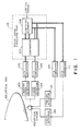
- Reference numeral 101 denotes an optical disc as a recording medium
- 102 indicates an optical system including an objective lens for converging a laser beam emitted from a laser source (not shown) like a spot onto the optical disc and irradiating the laser beam spot onto the optical disc in order to record and/or reproduce information onto/from the optical disc
- 103 a tracking error detector for detecting a relative position error signal (tracking error signal) in the tracking direction of the objective lens and the optical disc by a well-known method on the basis of the reflected lights which are obtained when the laser beam was irradiated onto the optical disc
- 104 a focus error detector for detecting a relative position error signal (focus error signal) in the focusing direction of the objective lens and the optical disc by a well-known method on the basis of the reflected lights which are obtained when the laser beam was irradiated onto the optical disc
- 105 an A/D converter to convert an analog output of the tracking error detector 103 into
- the computing element denotes a computing element in which the DSP or computing circuit to execute the calculations in accordance with the written programs is constructed in a hardware manner.
- various parameters can be changed by a control signal which is sent from the upper control unit (not shown).
- Reference numeral 110 denotes a D/A converter to convert a digital output of the computing element or comparator corresponding to the tracking error signal into an analog signal; 111 a D/A converter to convert a digital output of the computing element or comparator corresponding to the focus error signal into an analog signal; 112 a tracking actuator to drive the objective lens in the tracking direction on the basis of the output of the D/A converter 110; and 113 a focus actuator to drive the objective lens in the focusing direction on the basis of the output of the D/A converter 111.
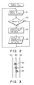
- Fig. 2 is a diagram showing a flow of the operation.
- the reflected lights from the optical disc 101 enter the optical system 2 and the tracking error signal is detected by the tracking error detector 103.
- the focus error signal is similarly detected by the focus error detector 104.
- the tracking error signal and focus error signal are converted into the digital signals by the A/D converters 105 and 106, respectively, and are input to the comparator 107 in a digital signal processing part 115 (step S1 in Fig. 2).
- step S2 digital signal processing part 115
- a check is made to see if the tracking error signal and/or focus error signal is set to "0" or not (step S2).
- the tracking error signal and/or focus error signal is not input to the computing element 108 but is input to the D/A converter 110 or 111, respectively. In this case, the controlled variables to the actuators are not changed but the objective lens is maintained in the same state.
- step S2 the comparator 107 inputs the tracking error signal and/or focus error signal to the computing element 108.
- the controlled variables of the tracking actuator 112 or focus actuator 113 are calculated from the input signal on the basis of predetermined calculating equations (step S3).
- the results of the calculations are output to the D/A converter 111 (step S4).
- the controlled variables which were converted into the analog values by the D/A converter 111 are input to the tracking actuator 112 or focus actuator 113.
- the tracking actuator 112 and focus actuator 113 drive the objective lens in the tracking and focusing directions in accordance with the controlled variables, respectively. That is, the tracking servo and focus servo are executed.
- Fig. 3 is a diagram showing an arrangment of beam spots 130, 131, and 132 on the recording medium from tracks 140 and the optical head.
- the tracking error signal is set to "0"
- the tracking of the beam spot 131 is correctly executed and there is no need to control by executing complicated calculations.
- the above circumstances are also the same as the case of the focus control of the in-focus state.
- Fig. 4 is a schematic diagram showing an example of a construction of an optical disc recording/reproducing apparatus in which the digital servo control apparatus of the invention is installed.
- Reference numeral 117 denotes an I/O (input/output) control part and 118 indicates a digital signal processor (hereinafter, abbreviated to DSP).
- DSP digital signal processor
- the DSP 118 executes discriminating and calculating processes in accordance with programs which have previously been written.
- various parameters filter constant and the like
- control signals which are sent from an upper control unit (not shown).
- the reflected lights from the optical disc 101 are input to the optical system 102 and a tracking error signal is detected by the tracking error detector 103.
- a focus error signal is detected by the focus error detector 104.
- the tracking error signal and the focus error signal are converted into the digital signals by the A/D converters 105 and 106, respectively, and are input to the DSP 118 through the I/O control part 117 (step S5).
- a check is made to see if the input servo error signal is set to "0" or not (step S6) (the discrimination in this step is executed in accordance with the program which has previously been written in the DSP 118). If it is "0", the operation to obtain the controlled variables which are necessary to accurately control the optical system 2 to a desired position by predetermined calculating equations is not executed but the controlled variables to the actuators are maintained in their states.
- the DSP 118 can assign the time when no calculating process is executed to the processes of the other control loops (not shown) or to the other processes (not shown) in the DSP 118.
- the control system can be simplified. If the servo error signal is not set to "0", in the DSP 118, the calculations are executed in accordance with the programs and the controlled variables are obtained (step S7) and are output to the D/A converters 110 and 111 through the I/O control part 117 (step S8).
- the calculations by the DSP 118 are executed by inputting the servo error signal which was sampled by a predetermined clock period.
- the controlled variables which were converted into the analog values by the D/A converters 110 and 111 are input to the tracking actuator 112 or focus actuator 113.
- the tracking actuator 112 and focus actuator 113 drive the objective lens in the tracking and focusing directions in accordance with the controlled variables, respectively. That is, the tracking servo and focus servo are performed.
- the present invention is not limited to the above embodiments but various other embodiments are possible.
- actuators are provided for other objects to be controlled, and the DSP 118 executes many calculating processes and can output the controlled variables to each of the actuators.
- the advantages of the invention can be obtained by constructing so as not to execute the calculations in a predetermined state in each control.
Landscapes
- Optical Recording Or Reproduction (AREA)
- Control Of Position Or Direction (AREA)
- Moving Of The Head To Find And Align With The Track (AREA)
- Feedback Control In General (AREA)
Applications Claiming Priority (4)
| Application Number | Priority Date | Filing Date | Title |
|---|---|---|---|
| JP73999/89 | 1989-03-28 | ||
| JP7399989 | 1989-03-28 | ||
| JP64306/90 | 1990-03-16 | ||
| JP2064306A JPH0348308A (ja) | 1989-03-28 | 1990-03-16 | デジタルサーボ制御装置 |
Publications (3)
| Publication Number | Publication Date |
|---|---|
| EP0390467A2 true EP0390467A2 (de) | 1990-10-03 |
| EP0390467A3 EP0390467A3 (de) | 1991-03-27 |
| EP0390467B1 EP0390467B1 (de) | 1995-06-28 |
Family
ID=26405423
Family Applications (1)
| Application Number | Title | Priority Date | Filing Date |
|---|---|---|---|
| EP90303199A Expired - Lifetime EP0390467B1 (de) | 1989-03-28 | 1990-03-26 | Digitales Servosteuergerät |
Country Status (4)
| Country | Link |
|---|---|
| US (1) | US5448542A (de) |
| EP (1) | EP0390467B1 (de) |
| JP (1) | JPH0348308A (de) |
| DE (1) | DE69020398T2 (de) |
Cited By (3)
| Publication number | Priority date | Publication date | Assignee | Title |
|---|---|---|---|---|
| EP0501570A1 (de) * | 1991-02-28 | 1992-09-02 | Koninklijke Philips Electronics N.V. | Digitales Regelsystem sowie Teilschaltung zur Anordnung im Regelsystem |
| EP0566778A3 (en) * | 1991-11-06 | 1993-12-01 | Sony Corp | Optical disk player with digital servo-control circuit |
| US5602689A (en) * | 1990-09-18 | 1997-02-11 | Rodime Plc | Digital servo control system for use in disk drives, including sample integrity tester for reducing effects of spurious sampled position values |
Families Citing this family (2)
| Publication number | Priority date | Publication date | Assignee | Title |
|---|---|---|---|---|
| JPH10214451A (ja) * | 1997-01-29 | 1998-08-11 | Alpine Electron Inc | デジタルディスクプレーヤ |
| JP2002124047A (ja) * | 2000-10-11 | 2002-04-26 | Sony Corp | 磁気ディスク装置 |
Family Cites Families (10)
| Publication number | Priority date | Publication date | Assignee | Title |
|---|---|---|---|---|
| US4907214A (en) * | 1985-12-18 | 1990-03-06 | Kabushiki Kaisha Toshiba | Eccentricity correction apparatus for an optical disk device |
| JPS62293522A (ja) * | 1986-06-13 | 1987-12-21 | Pioneer Electronic Corp | 記録デイスク再生装置 |
| JPS62298931A (ja) * | 1986-06-18 | 1987-12-26 | Sony Corp | 光デイスクに対するデジタルサ−ボ方式 |
| DE3783114T2 (de) * | 1986-09-20 | 1993-04-22 | Pioneer Electronic Corp | Servomechanismus fuer eine aufzeichnungsplatte-wiedergabeanordnung. |
| JPS63213126A (ja) * | 1987-02-27 | 1988-09-06 | Nec Corp | 光デイスク装置 |
| JPH0821210B2 (ja) * | 1987-07-09 | 1996-03-04 | 日本電気株式会社 | 位置誤差補償方式 |
| JP2557896B2 (ja) * | 1987-07-31 | 1996-11-27 | 株式会社東芝 | ディスク装置 |
| NL8702261A (nl) * | 1987-09-23 | 1989-04-17 | Philips Nv | Informatie opteken en/of uitlees systeem, alsmede een registratiedrager en opteken en/of uitleesinrichting voor toepassing in een dergelijk systeem. |
| JPH0782721B2 (ja) * | 1988-10-05 | 1995-09-06 | パイオニア株式会社 | ディスクプレーヤのサーボ装置 |
| US5235577A (en) * | 1989-11-02 | 1993-08-10 | Canon Kabushiki Kaisha | Information recording and/or reproducing apparatus for timing switching of a jumping pulse from an intermittently detected tracking signal |
-
1990
- 1990-03-16 JP JP2064306A patent/JPH0348308A/ja active Pending
- 1990-03-26 EP EP90303199A patent/EP0390467B1/de not_active Expired - Lifetime
- 1990-03-26 DE DE69020398T patent/DE69020398T2/de not_active Expired - Fee Related
-
1993
- 1993-09-10 US US08/118,687 patent/US5448542A/en not_active Expired - Fee Related
Cited By (16)
| Publication number | Priority date | Publication date | Assignee | Title |
|---|---|---|---|---|
| US5675450A (en) * | 1990-09-18 | 1997-10-07 | Rodime, P.L.C. | Digital servo control system for use in disk drives using driver saturation model |
| US5677809A (en) * | 1990-09-18 | 1997-10-14 | Rodime Plc | Digital servo control system for use in disk drives, having state space observer including integral compensator |
| US5914829A (en) * | 1990-09-18 | 1999-06-22 | Rodime Plc | Digital servo control system for use in disk drives, including calibrated controller for fixed-distance seeks |
| US5914830A (en) * | 1990-09-18 | 1999-06-22 | Rodime Plc | Digital servo control system including sample integrity tester for reducing effects of spurious sampled position values |
| US5602689A (en) * | 1990-09-18 | 1997-02-11 | Rodime Plc | Digital servo control system for use in disk drives, including sample integrity tester for reducing effects of spurious sampled position values |
| US5684650A (en) * | 1990-09-18 | 1997-11-04 | Rodime, Plc | Digital servo control system for use in disk drives |
| US5680272A (en) * | 1990-09-18 | 1997-10-21 | Rodime Plc | Digital servo control system for use in disk drives |
| US5638230A (en) * | 1990-09-18 | 1997-06-10 | Rodime Plc | Digital servo control system for use in disk drives |
| US5646797A (en) * | 1990-09-18 | 1997-07-08 | Rodime Plc | Digital servo control system for use in disk drives |
| EP0501570A1 (de) * | 1991-02-28 | 1992-09-02 | Koninklijke Philips Electronics N.V. | Digitales Regelsystem sowie Teilschaltung zur Anordnung im Regelsystem |
| US5249116A (en) * | 1991-02-28 | 1993-09-28 | U.S. Philips Corporation | Digital control system and a sub-circuit to be used in the control system |
| US5682307A (en) * | 1991-11-06 | 1997-10-28 | Sony Corporation | Circuits and methods for controlling a tracking actuator of an optical disk player |
| US5623465A (en) * | 1991-11-06 | 1997-04-22 | Sony Corporation | Optical disk player with a digital servo-control circuit incorporating a time sharing multifunctional digital filter |
| EP0739002A1 (de) * | 1991-11-06 | 1996-10-23 | Sony Corporation | Optischer Plattenspieler mit digitalem Servo-Kreis |
| EP0566778A3 (en) * | 1991-11-06 | 1993-12-01 | Sony Corp | Optical disk player with digital servo-control circuit |
| KR100272118B1 (ko) * | 1991-11-06 | 2000-11-15 | 이데이 노부유끼 | 디지탈 서보 제어 회로를 구비한 광디스크 플레이어 및 트래킹 서보 회로 |
Also Published As
| Publication number | Publication date |
|---|---|
| DE69020398D1 (de) | 1995-08-03 |
| JPH0348308A (ja) | 1991-03-01 |
| US5448542A (en) | 1995-09-05 |
| DE69020398T2 (de) | 1995-11-09 |
| EP0390467B1 (de) | 1995-06-28 |
| EP0390467A3 (de) | 1991-03-27 |
Similar Documents
| Publication | Publication Date | Title |
|---|---|---|
| US4611317A (en) | Optical disk apparatus | |
| US4751695A (en) | Method and apparatus for tracking servo system | |
| US5218588A (en) | Focus offset correction method | |
| US6442109B1 (en) | Motor control apparatus, motor control method, disk apparatus and disk access method for correcting an assumed value based on error information | |
| US6249496B1 (en) | Optical storage apparatus | |
| EP0363022B1 (de) | Spursignal in einem optischen Informationsaufzeichnungs- und/oder -wiedergabegerät | |
| US5142518A (en) | Gain control system for error signal amplifier in tracking servo apparatus | |
| US4918680A (en) | Focus-servo correction utilizing storage of detected focus errors | |
| EP0776000B1 (de) | System zur Wiedergabe von Informationen | |
| US5448542A (en) | Optical information recording and reproducing apparatus including a computing unit for calculating tracking and focusing error correction values | |
| EP1248255B1 (de) | Fokussierungsregler für die Kontrolle eines Sprunges zwischen Aufzeichnungsschichten | |
| US4901298A (en) | Track pulse controlled address search method for optical disk player | |
| US5123002A (en) | Disc player servo device | |
| US5086420A (en) | Focus control apparatus for use with an optical disk for determining whether a focused state has been obtained | |
| US5185730A (en) | Method for reading data from optical disk | |
| US5483507A (en) | Information recording and/or reproducing method and apparatus including head seek distance and direction control based on address information | |
| US4989194A (en) | Optical information processing method of driving auto-focusing and/or auto-tracking means in accordance with a stored servo signal when irradiation of a record medium with light beam is stopped, and apparatus therefor | |
| US5124964A (en) | Focus servo gain setting circuit for optical record disc reproducing apparatus | |
| EP0395403A2 (de) | Optisches Informationsaufnahme-/-wiedergabegerät mit digitaler Servoeinrichtung zum Fokussieren und/oder zur Spurfolge eines optischen Kopfes, basierend auf digitale Information | |
| US5659527A (en) | Optical disk drive with use of sampled preceding focus or tracking error signal in response to detection of spiked noise or offset | |
| US5485440A (en) | Optical information recording/reproducing apparatus comprising digital servo device for performing focusing and/or tracking of optical head based on digital information | |
| JP3228403B2 (ja) | 光ディスク記録再生装置 | |
| JPH0536099A (ja) | 情報記録再生装置 | |
| JP2794805B2 (ja) | フォーカシング制御装置 | |
| JPH0628697A (ja) | 光ディスクプレーヤ |
Legal Events
| Date | Code | Title | Description |
|---|---|---|---|
| PUAI | Public reference made under article 153(3) epc to a published international application that has entered the european phase |
Free format text: ORIGINAL CODE: 0009012 |
|
| AK | Designated contracting states |
Kind code of ref document: A2 Designated state(s): DE FR GB IT NL |
|
| PUAL | Search report despatched |
Free format text: ORIGINAL CODE: 0009013 |
|
| 17P | Request for examination filed |
Effective date: 19901231 |
|
| AK | Designated contracting states |
Kind code of ref document: A3 Designated state(s): DE FR GB IT NL |
|
| 17Q | First examination report despatched |
Effective date: 19930913 |
|
| GRAA | (expected) grant |
Free format text: ORIGINAL CODE: 0009210 |
|
| AK | Designated contracting states |
Kind code of ref document: B1 Designated state(s): DE FR GB IT NL |
|
| REF | Corresponds to: |
Ref document number: 69020398 Country of ref document: DE Date of ref document: 19950803 |
|
| ITF | It: translation for a ep patent filed | ||
| ET | Fr: translation filed | ||
| PLBE | No opposition filed within time limit |
Free format text: ORIGINAL CODE: 0009261 |
|
| STAA | Information on the status of an ep patent application or granted ep patent |
Free format text: STATUS: NO OPPOSITION FILED WITHIN TIME LIMIT |
|
| 26N | No opposition filed | ||
| REG | Reference to a national code |
Ref country code: GB Ref legal event code: IF02 |
|
| PGFP | Annual fee paid to national office [announced via postgrant information from national office to epo] |
Ref country code: NL Payment date: 20060315 Year of fee payment: 17 |
|
| PGFP | Annual fee paid to national office [announced via postgrant information from national office to epo] |
Ref country code: FR Payment date: 20060317 Year of fee payment: 17 Ref country code: GB Payment date: 20060317 Year of fee payment: 17 |
|
| PGFP | Annual fee paid to national office [announced via postgrant information from national office to epo] |
Ref country code: IT Payment date: 20060331 Year of fee payment: 17 |
|
| PGFP | Annual fee paid to national office [announced via postgrant information from national office to epo] |
Ref country code: DE Payment date: 20060518 Year of fee payment: 17 |
|
| GBPC | Gb: european patent ceased through non-payment of renewal fee |
Effective date: 20070326 |
|
| NLV4 | Nl: lapsed or anulled due to non-payment of the annual fee |
Effective date: 20071001 |
|
| REG | Reference to a national code |
Ref country code: FR Ref legal event code: ST Effective date: 20071130 |
|
| PG25 | Lapsed in a contracting state [announced via postgrant information from national office to epo] |
Ref country code: DE Free format text: LAPSE BECAUSE OF NON-PAYMENT OF DUE FEES Effective date: 20071002 Ref country code: NL Free format text: LAPSE BECAUSE OF NON-PAYMENT OF DUE FEES Effective date: 20071001 |
|
| PG25 | Lapsed in a contracting state [announced via postgrant information from national office to epo] |
Ref country code: GB Free format text: LAPSE BECAUSE OF NON-PAYMENT OF DUE FEES Effective date: 20070326 |
|
| PG25 | Lapsed in a contracting state [announced via postgrant information from national office to epo] |
Ref country code: FR Free format text: LAPSE BECAUSE OF NON-PAYMENT OF DUE FEES Effective date: 20070402 |
|
| PG25 | Lapsed in a contracting state [announced via postgrant information from national office to epo] |
Ref country code: IT Free format text: LAPSE BECAUSE OF NON-PAYMENT OF DUE FEES Effective date: 20070326 |