EP0390601B1 - Informationsaufzeichnungsmedium und Informationsaufzeichnungs/-Wiedergabemethode und -vorrichtung, die dergleichen verwendet - Google Patents
Informationsaufzeichnungsmedium und Informationsaufzeichnungs/-Wiedergabemethode und -vorrichtung, die dergleichen verwendet Download PDFInfo
- Publication number
- EP0390601B1 EP0390601B1 EP90303466A EP90303466A EP0390601B1 EP 0390601 B1 EP0390601 B1 EP 0390601B1 EP 90303466 A EP90303466 A EP 90303466A EP 90303466 A EP90303466 A EP 90303466A EP 0390601 B1 EP0390601 B1 EP 0390601B1
- Authority
- EP
- European Patent Office
- Prior art keywords
- disk
- clock signal
- reference clock
- zone
- frequency
- Prior art date
- Legal status (The legal status is an assumption and is not a legal conclusion. Google has not performed a legal analysis and makes no representation as to the accuracy of the status listed.)
- Expired - Lifetime
Links
- 238000000034 method Methods 0.000 title claims description 19
- 230000003287 optical effect Effects 0.000 claims description 30
- 238000001514 detection method Methods 0.000 claims description 11
- 102000001999 Transcription Factor Pit-1 Human genes 0.000 description 8
- 108010040742 Transcription Factor Pit-1 Proteins 0.000 description 8
- 238000005070 sampling Methods 0.000 description 4
- 239000004065 semiconductor Substances 0.000 description 4
- 238000006243 chemical reaction Methods 0.000 description 2
- 230000005381 magnetic domain Effects 0.000 description 2
- 230000005374 Kerr effect Effects 0.000 description 1
- 238000013459 approach Methods 0.000 description 1
- 230000001276 controlling effect Effects 0.000 description 1
- 230000002596 correlated effect Effects 0.000 description 1
- 230000001419 dependent effect Effects 0.000 description 1
- 238000010586 diagram Methods 0.000 description 1
- 230000001360 synchronised effect Effects 0.000 description 1
Images




Classifications
-
- G—PHYSICS
- G11—INFORMATION STORAGE
- G11B—INFORMATION STORAGE BASED ON RELATIVE MOVEMENT BETWEEN RECORD CARRIER AND TRANSDUCER
- G11B7/00—Recording or reproducing by optical means, e.g. recording using a thermal beam of optical radiation by modifying optical properties or the physical structure, reproducing using an optical beam at lower power by sensing optical properties; Record carriers therefor
- G11B7/007—Arrangement of the information on the record carrier, e.g. form of tracks, actual track shape, e.g. wobbled, or cross-section, e.g. v-shaped; Sequential information structures, e.g. sectoring or header formats within a track
- G11B7/00745—Sectoring or header formats within a track
-
- G—PHYSICS
- G11—INFORMATION STORAGE
- G11B—INFORMATION STORAGE BASED ON RELATIVE MOVEMENT BETWEEN RECORD CARRIER AND TRANSDUCER
- G11B20/00—Signal processing not specific to the method of recording or reproducing; Circuits therefor
- G11B20/10—Digital recording or reproducing
- G11B20/12—Formatting, e.g. arrangement of data block or words on the record carriers
- G11B20/1217—Formatting, e.g. arrangement of data block or words on the record carriers on discs
- G11B20/1258—Formatting, e.g. arrangement of data block or words on the record carriers on discs where blocks are arranged within multiple radial zones, e.g. Zone Bit Recording or Constant Density Recording discs, MCAV discs, MCLV discs
-
- G—PHYSICS
- G11—INFORMATION STORAGE
- G11B—INFORMATION STORAGE BASED ON RELATIVE MOVEMENT BETWEEN RECORD CARRIER AND TRANSDUCER
- G11B7/00—Recording or reproducing by optical means, e.g. recording using a thermal beam of optical radiation by modifying optical properties or the physical structure, reproducing using an optical beam at lower power by sensing optical properties; Record carriers therefor
- G11B7/007—Arrangement of the information on the record carrier, e.g. form of tracks, actual track shape, e.g. wobbled, or cross-section, e.g. v-shaped; Sequential information structures, e.g. sectoring or header formats within a track
- G11B7/0079—Zoned data area, e.g. having different data structures or formats for the user data within data layer, Zone Constant Linear Velocity [ZCLV], Zone Constant Angular Velocity [ZCAV], carriers with RAM and ROM areas
Definitions
- the present invention relates to a disk-shaped information recording medium having concentric or spiral tracks on which servo signals for detecting the tracking error are recorded in discrete manner, and a method and an apparatus for recording and/or reproducing information, utilizing said recording medium.
- Optical disk apparatus are commonly known as an apparatus for recording and/or reproducing information on a disk-shaped information recording medium.
- tracking servo for causing a light spot to track the information track, in which an objective lens working as light collecting means is moved by the deviation of the light spot from the information track, detected by optical means.
- detection of deviation is for example achieved by a discrete time method, usually called sampling servo method.
- a front (or preceding) wobble pit 2 and a rear (or succeeding) wobble pit 4 are positioned with a deviation of about 1/4 track pitch on both sides of an imaginary (or virtual) track 1, and the deviation from said imaginary track is detected on the basis of the optical modulation by such wobble pits.
- the optical disk is rotated at a constant angular velocity, and, if the light spot passes over the pits on a trace line A deviated toward the periphery of the disk, on the imaginary track 1, and on a trace line B deviated toward the center of the disk as shown in Fig. 2, the light spot is modulated by said wobble pits as indicated by curves e, f and g in Fig. 2, perspectively.
- a clock pit 3 is used for generating a reference clock signal for extracting a tracking error signal.
- the wobble pit train consisting of the front wobble pit 2, clock pit 3 and rear wobble pit 4 is positioned at a constant angular interval in the circumferential direction of the optical disk. Accordingly, when the optical disk is rotated at a constant angular velocity, the light spot periodically passes the wobble pit train.
- a signal indicating the peak of modulation by the clock pit 3 is generated and a reference clock signal h shown in Fig. 2 is generated by a phase-locked loop (PLL) circuit.
- PLL phase-locked loop
- the tracking error signal is obtained by sample-holding the modulation signal based on the front wobble pit 2 at a time t 1 (at the setup of the reference clock signal), shown in Fig. 2, then sample-holding the modulation signal based on the rear wobble pit 4 at a time t 2 , and subtracting the latter signal from the former signal.
- the subtraction When the light spot is on the trace line A, the subtraction provides a positive result as the modulation by the front wobble pit 2 is larger than that by the rear wobble pit 4, and when the light spot is on the trace line B, the subtraction provides a negative result as the modulation by the front wobble pit 2 is smaller than that by the rear wobble pit 4.
- Said tracking error signal is detected from the wobble pit trains at a substantially constant interval, namely in discrete time manner.
- the modulation signal resulting from the wobble pit train is generally repeated at a constant interval over the entire surface of the optical disk. This is particularly effective in a seeking operation. In case of radially moving the light spot and effecting the tracking servo operation on a desired track, if the modulation signals resulting from the wobble pit trains do not appear periodically before and after said movement, there is again required the locking function of the PLL circuit so as to generate the reference clock signal for extracting the tracking error signal, so that prompt capture operation of tracking servo is difficult.
- the reference clock signal for extracting the tracking error signal also as the reference clock signal for the digital information to be recorded between two wobble pit trains.
- the digital information is recorded by modulating the beam of a semiconductor laser in synchronization with the reference clock signal h shown in Fig. 2, thereby recording marks in the form of pits (in case of write once read many type), magnetic domains (in case of photo-electro-magnetic type) or the like in the information recording film between two wobble pit trains.
- the reproduction of information can also be achieved by identifying the presence or absence of said marks, by inspecting the signal obtained by photoelectric conversion of the light reflected from the disk at timings synchronized with said reference clock signal h shown in Fig. 2.
- MCAV constant angular velocity
- WO-A-88/04824 discloses an information recording disk designed to be rotated at a constant linear velocity leading to a variable angular velocity.
- the recording tracks are grouped into a plurality of annular zones wherein each track within a given zone has a fixed number of radially aligned tracking pads.
- EP-A-0278006 discloses an information recording disk in which there is provided a servo signal region in which servo signals in the form of pits are formed, and an address signal region in which data and address signals are written.
- EP-A-0218214 discloses an optical disk apparatus for use with an optical disk in which either the data signals are of constant frequency regardless of the access position on the disk, or vary dependent on the access position.
- the object of the present invention is to provide an information recording disk enabling secure tracking operation and still providing a large recording capacity, and a method and an apparatus for recording and/or reproduction utilizing said disk.
- an information recording disk on which the tracks are concentrically or spirally provided in a plurality of zones (A-G) in a radial direction, each zone containing one or more of tracks (21) each track being divided into a plurality of sectors each of a predetermined number of bytes, servo signals for detecting tracking errors being discretely recorded on the tracks, the recording or reproducing frequency for recording or reproducing information on the disk being greater at a track at an outer zone of the disc than at a track at an inner zone of the disk such that the recording density is substantially the same in inner and outer zones of the disk,
- Fig. 3 is a schematic view showing an embodiment of the information record/reproducing apparatus of the present invention, wherein an information recording medium 9 is composed of a magneto-optical (photo-electro-magnetic) disk with a diameter of 86 mm.
- the signal recording and reproduction are conducted in an area, from 48 to 80 mm in diameter, of said disk.
- a motor 10 is provided for rotating said disk at 3600 rpm, and the revolution of said motor is controlled by a revolution controller (not shown).
- An optical head 11 incorporates therein a semiconductor laser of a wavelength 830 nm constituting a light source, a collimating lens, an objective lens, an actuator for moving said objective lens in the focusing direction and in the tracking direction, a polarizing beam splitter, and a PIN photodiode serving as a photoelectric converter, and focuses the beam emitted from the semiconductor laser onto the disk 9 by unrepresented means, maintaining the light spot in about 1.5 ⁇ m in the half-peak width.
- the reflected light from the disk 9 enters the PIN photodiode, whereby the optical modulation by the pits embossed on said disk 9 and the modulation caused by the Kerr effect of the magnetic domain marks can both be photoelectrically converted by said PIN photodiode and supplied to a signal processing unit 13.
- a linear motor 12 for moving the optical head 11 in the radial direction of the disk 9, and a control unit 14 for controlling the tracking actuator of the optical head 11 and the linear motor 12, based on the tracking error signal and the address information obtained from the signal processing unit 13.
- a record/reproducing area is defined from 40 to 24 mm in radius, in which servo bytes, to be explained later, are provided in a number of 1672 per turn, in spiral pattern with a radial pitch of 1.5 ⁇ m.
- the record/reproducing area contains 10,666 imaginary tracks in spiral pattern with a pitch of 1.5 ⁇ m.
- the record/reproducing area is divided, as shown in Fig. 4, in seven concentric zones A - G.
- the digital information is recorded or reproduced by a unit of 512 bytes, but the actual recording data consist of 584 bytes including the error correction code (ECC) and the control data.
- ECC error correction code
- Said recording data are encoded by 4/11 encoding and recorded by NRZ (non return to zero) modulation.
- the logic bit 1 or 0 respectively corresponds to the presence or absence of a mark.
- the 4/11 encoding is used for converting 8-bit data into an 11-bit code as already known, but will not be explained in detail as it is not directly related to the present invention.
- the actual recording data of 584 bytes are recorded in or reproduced from each sector constituting a recording unit on the magneto-optical (photo-electro-magnetic) disk.
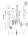
- Said sector is defined by dividing the track of a turn into a plural number.
- the first block #0 is not available for recording, and contains a sector mark for identifying the start of a sector, a track address and a sector address, all by embossed pits.
- Ensuing blocks #1, #2 are available for recording, and record a logic sector address, of which record/reproducing bit rate is equal to the servo channel bit rate to be explained later.
- servo bytes which are divided into 22 servo channel bits.
- the rate of said servo channel bits is same for each of the zones, and is 60 (Hz) x 1672 (blocks/turn) x 110 (servo channel bits/block) ⁇ 11.04 Mbps.
- the servo bytes are followed by the aforementioned actual recording data of 584 bytes, but the number m of bytes of actual recording data per block varies according to the zone.
- the data channel bit rate in the data area of the block varies depending on the zone, and the ratio of said rates is equal to the ratio of the number of bytes of actual recording data in the blocks.
- a relative track address is formed as an access mark, in the form of encoded embossed pits. This pattern is repeated in every 18 tracks, and is used for detecting the distance to the desired track in the course of movement of the optical head 11 by the linear motor 12 in a seeking operation, thereby increasing the speed of the seeking operation.
- 11th to 17th bits there are formed, as shown in the lower part of Fig.
- the signal processing unit 13 shown in Fig. 3 includes 2-stage PLL circuits as shown in Fig. 6, wherein the first PLL circuit, for generating the servo reference clock signal from a clock pit signal generated when the light spot passes through the clock pit, is composed of a phase comparator 5, a loop filter 6, a voltage-controlled oscillator (VCO) 7, and a 1/110 frequency divider 8.
- the second PLL circuit for generating a data reference clock signal by receiving a frequency-divided signal obtained by a 1/8 frequency divider 15 from the servo reference clock signal generated in the first PLL circuit, is composed of a phase comparator 16, a loop filter 17, a VCO 18, and a frequency divider 19 with variable frequency dividing ratio.
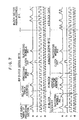
- a signal a obtained by photoelectric conversion in the photodetector the optical head shows modulations by embossed marks and magneto-optical marks by approximately same amplitudes.
- a clock pit signal b is a pulse signal generated at the peak of the clock pit at each servo bytes.
- the servo reference clock signal c is generated by entering the clock pit signal into the first PLL circuit shown in Fig. 6, and the data reference clock signal d is similarly generated by the second PLL circuit shown in Fig. 6.
- the 1/8 frequency divider 15 of the second PLL circuit is reset by the clock pit signal of the block #1, in order to start the frequency division once in each sector and to match the phase of the data reference clock signal.
- the identification of marks, including the servo bytes is conducted by the servo reference clock signal.
- the mark identification is conducted with the servo reference clock signal for the servo bytes only, and with the data reference clock signal in the data area.
- the voltages are subjected to sample-holding approximately at the centers by the servo reference clock signal, and are then subjected to subtraction to generate the tracking error signal.
- the control unit 14 drives the tracking actuator of the optical head 11, thereby achieving the tracking servo operation and causing the light spot to follow the imaginary track.
- the data reference clock signal is used for defining the start point of the data area, there are obtained 24 or 25 counts, depending on the block.
- the number of channel bits of the servo bytes is not a multiple of the number of data bytes actually recorded by the servo reference clock signal in the data area, namely not a multiple of 8.
- the number of channel bits of the servo bytes is selected as 24 bits as shown in Fig. 8.
- the 1/110 frequency divider 8 in Fig. 6 is replaced by a 1/112 frequency divider. Consequently the count of the data reference clock signal in the servo bytes becomes an integer, so that the number of the data reference clock pulses in each block becomes also an integer.
- the present invention is not limited to the foregoing embodiments but is subject to various applications.
- the tracks may be formed concentrically instead of spirally.
- the present invention is applicable to a magnetic disk and a magnetic disk apparatus in which information recording and reproduction are conducted with a magnetic head.
- the present invention includes all such applications within the scope of the appended claims.
Landscapes
- Engineering & Computer Science (AREA)
- Signal Processing (AREA)
- Software Systems (AREA)
- Theoretical Computer Science (AREA)
- Signal Processing For Digital Recording And Reproducing (AREA)
- Optical Recording Or Reproduction (AREA)
- Manufacturing Optical Record Carriers (AREA)
Claims (20)
- Informationsaufzeichnungsmedium (9), auf dem Spuren (21) konzentrisch oder spiralförmig in einer Vielzahl von in radialer Richtung ausgebildeten Zonen (A-G) ausgebildet sind, wobei jede Zone eine oder mehrere Spuren (21) enthält und jede Spur in eine Vielzahl von jeweils eine vorbestimmte Anzahl von Bytes umfassenden Sektoren unterteilt ist, wobei Servosignale (22, 24) zur Erfassung von Spurführungsfehlern einzeln auf den Spuren (21) aufgezeichnet sind, wobei eine Aufzeichnungs- oder Wiedergabefrequenz zur Aufzeichnung oder Wiedergabe von Informationen auf/von dem Medium bei einer Spur in einer äußeren Zone des Mediums (9) größer als bei einer Spur in einer inneren Zone des Mediums (9) ist, so daß die Aufzeichnungsdichte in der inneren und der äußeren Zone des Mediums (9) im wesentlichen die gleiche ist, wobei das Medium
dadurch gekennzeichnet ist, daß
die Sektoren in eine Vielzahl von Blöcken unterteilt sind, wobei in jedem Block ein Servosignal aufgezeichnet ist, wobei die Anzahl der Blöcke pro Sektor in der inneren Zone des Mediums (9) größer als in der äußeren Zone des Mediums (9) ist, so daß die Servosignale in inneren und äußeren Zonen des Mediums (9) dieselbe Frequenz aufweisen. - Informationsaufzeichnungsmedium (9) nach Anspruch 1,
dadurch gekennzeichnet, daß
die Anzahl von Servosignalen pro Sektor in einer Zone konstant, aber zwischen verschiedenen Zonen unterschiedlich ist. - Informationsaufzeichnungsmedium nach Anspruch 1,
dadurch gekennzeichnet, daß
ein Adressignal in dem ersten Block in jeden der Sektoren mit einer Bitrate aufgezeichnet ist, die gleich der des Servosignals ist. - Informationsaufzeichnungsmedium nach Anspruch 1,
dadurch gekennzeichnet, daß
die Servosignale aus einer in der Mittelposition einer Spur (21) ausgebildeten Taktvertiefung (23), und ersten und zweiten Wobbelvertiefungen (22, 24) bestehen, die in entgegengesetzten Richtungen in von der Mitte der Spur (21) abweichenden Positionen ausgebildet sind. - Informationsaufzeichnungsmedium nach Anspruch 1,
dadurch gekennzeichnet, daß
das Medium eine optische Platte (9)ist, bei der die Informationsaufzeichnung/-wiedergabe durch Bestrahlung mit einem Lichtstrahl erfolgt. - Informationsaufzeichnungsmedium nach Anspruch 5,
dadurch gekennzeichnet, daß
die Platte (9) eine magneto-optische Platte ist. - Verfahren zur Informationsaufzeichnung auf und/oder Informationswiedergabe von einem gemäß Anspruch 1 definierten Informationsaufzeichnungsmedium (9), mit den SchrittenRotieren des Mediums (9) mit konstanter Winkelgeschwindigkeit,Erzeugen eines ersten Bezugstaktsignals konstanter Frequenz (F1) aus dem auf dem Medium (9) aufgezeichneten Servosignal,Erzeugen eines zweiten Bezugstaktsignals, dessen Frequenz (F2) in einer äußeren Zone des Mediums (9) höher ist als in einer inneren Zone des Mediums (9),Erfassen von Spurführungsfehlern auf der Grundlage der auf einer gewünschten Spur (21) des Mediums (9) aufgezeichneten Servosignalen unter Verwendung des ersten Bezugstaktsignals,Durchführen der Spurführungssteuerung unter Verwendung der erfaßten Spurführungsfehler, undDurchführen der Aufzeichnung von Informationen auf und/oder der Wiedergabe von Informationen von der gewünschten Spur (21) auf der Grundlage des zweiten Bezugstaktsignals.
- Verfahren nach Anspruch 7, bei dem
die Frequenz des zweiten Bezugstaktsignals so gesteuert wird, daß sie innerhalb einer Zone konstant, aber abhängig von der Zone veränderlich ist. - Verfahren nach Anspruch 8, bei dem
jede der Spuren auf der Grundlage der Servosignale in Umfangsrichtung in eine Vielzahl von Blöcken aufgeteilt ist, und die Anzahl von Bytes der tatsächlich in jedem Block aufgezeichneten Daten eine ganze Zahl ist, die sich entsprechend der Zone, zu der der Block gehört ändert. - Verfahren nach Anspruch 9, bei dem
das Verhältnis von Frequenzen des zweiten Bezugstaktsignals in verschiedenen Zonen (A-G) gleich dem Verhältnis der Anzahl von Bytes von tatsächlich pro Block in den Zonen (A-G) aufgezeichneten Daten ist. - Verfahren nach Anspruch 9, bei dem
die Anzahl von Kanalbits von jedem der Servosignale ein ganzzahliges Vielfaches der Anzahl von Bytes von tatsächlich mit der Rate des ersten Bezugstaktsignals pro Block aufgezeichneten Daten ist. - Vorrichtung zur Durchführung der Aufzeichung von Informationen auf einem Informationsaufzeichnungsmedium (9) nach Anspruch 1, miteinem Motor (10) zur Drehung des Mediums (9) mit einer konstanten Winkelgeschwindigkeit,einer ein erstes Taktsignal erzeugenden Schaltung (5, 6, 7, 8) zur Erzeugung eines ersten Bezugstaktsignals konstanter Frequenz (F1) auf der Grundlage der auf einer gewünschten Spur des Mediums (9) aufgezeichneten Servosignale (23),einer ein zweites Taktsignal erzeugenden Schaltung (15, 16, 17, 18, 19) zur Erzeugung eines zweiten Bezugstaktsignals aus dem ersten Bezugstaktsignal, wobei die Schaltung die Frequenz (F2) des zweiten Bezugstaktsignals so ändert, daß diese höher ist, wenn die gewünschte Spur in einer äußeren Zone des Mediums (9) liegt,einer Fehlererfassungsschaltung (13) zur Spurführungsfehlererfassung auf der Grundlage des auf der gewünschten Spur aufgezeichneten Servosignals unter Verwendung des ersten Bezugstaktsignals,einem Kopf (11) zur Durchführung der Informationsaufzeichnung auf der gewünschten Spur beruhend auf dem zweiten Bezugstaktsignal, undeine Steuerungsschaltung (14) zur Durchführung der Spurführungssteuerung des Kopfs unter Verwendung des von der Fehlererfassungsschaltung (13) erfaßten Spurführungsfehlers.
- Vorrichtung zur Durchführung der Wiedergabe von auf einem Informationsaufzeichnungsmedium (9) nach Anspruch 1 aufgezeichneten Informationen, miteinem Motor (10) zur Drehung des Mediums (9) mit einer konstanten Winkelgeschwindigkeit,einer ein erstes Taktsignal erzeugenden Schaltung (5, 6, 7, 8) zur Erzeugung eines ersten Bezugstaktsignals konstanter Frequenz (F1) auf der Grundlage der auf einer gewünschten Spur des Mediums (9) aufgezeichneten Servosignale (23),einer ein zweites Taktsignal erzeugenden Schaltung (15, 16, 17, 18, 19) zur Erzeugung eines zweiten Bezugstaktsignals aus dem ersten Bezugstaktsignal, wobei die Schaltung die Frequenz (F2) des zweiten Bezugstaktsignals so ändert, daß diese höher ist, wenn die gewünschte Spur in einer äußeren Zone des Mediums (9) liegt,einer Fehlererfassungsschaltung (13) zur Spurführungsfehlererfassung auf der Grundlage des auf der gewünschten Spur aufgezeichneten Servosignals unter Verwendung des ersten Bezugstaktsignals,einem Kopf (11) zur Durchführung der Informationswiedergabe von der gewünschten Spur beruhend auf dem zweiten Bezugstaktsignal, undeiner Steuerschaltung (14) zur Durchführung der Spurführungssteuerung des Kopfs unter Verwendung des von der Fehlererfassungsschaltung (13) erfaßten Spurführungsfehlers.
- Vorrichtung nach Anspruch 13, mit der
auch Informationen auf das Medium (9) aufgezeichnet werden können. - Vorrichtung nach Anspruch 12, 13 oder 14, wobei
die ein erstes Taktsignal erzeugende Schaltung (5, 6, 7, 8) eine PLL-Schaltung ist, die aus einem ersten spannungsgesteuerten Oszillator (7) zur Erzeugung eines ersten Bezugstaktsignals, einem Frequenzteiler (8) zum Teilen der Frequenz des Ausgangssignals des ersten Oszillators (7), und aus einem Phasenvergleicher (5) zum Vergleichen der Phase des Ausgangssignals des Frequenzteilers (8) mit der des durch den Kopf (11) gelesenen Servosignals besteht, wodurch der erste Oszillator (7) gesteuert wird. - Vorrichtung nach Anspruch 12, 13 oder 14, wobei
die ein zweites Taktsignal erzeugende Schaltung (15, 16, 17, 18, 19) eine PLL-Schaltung ist, die aus einem spannungsgesteuerten Oszillator (18) zur Erzeugung eines zweiten Bezugstaktsignals, einem ersten Frequenzteiler (19) mit veränderlicher Frequenzteilungsrate zum Teilen der Frequenz des Ausgangssignals des zweiten Oszillators (18), einem zweiten Frequenzteiler (15) zum Teilen der Frequenz (F2) des ersten Bezugstaktsignals, und einem Phasenvergleicher (16) zum Vergleichen der Phase des Ausgangssignals des ersten Frequenzteilers (19) mit der des Ausgangssignals des zweiten Frequenzteilers (15), wodurch der zweite Oszillator (18) gesteuert wird. - Vorrichtung nach Anspruch 12, 13 oder 14, wobei
die ein zweites Taktsignal erzeugende Schaltung (15, 16, 17, 18, 19) jedesmal dann zurückgesetzt wird, wenn der Kopf an einem Sektor vorbeifährt. - Vorrichtung nach Anspruch 12, 13 oder 14, wobei
die ein zweites Taktsignal erzeugende Schaltung (15, 16, 17, 18, 19) die Frequenz des zweiten Bezugstaktsignals so steuert, daß sie innerhalb einer jeden Zone (A-G) konstant, aber abhängig von der Zone (A-G) verschieden ist. - Vorrichtung nach Anspruch 12 oder 14, wobei
der Kopf ein optischer Kopf (11) zur Informationsaufzeichnung durch Bestrahlung des Mediums (9) mit einem Lichtstrahl ist. - Vorrichtung nach Anspruch 13 oder 14, wobei
der Kopf ein optischer Kopf (11) zur Informationswiedergabe durch Bestrahlung des Mediums (9) mit einem Lichtstrahl ist.
Applications Claiming Priority (2)
| Application Number | Priority Date | Filing Date | Title |
|---|---|---|---|
| JP83207/89 | 1989-03-31 | ||
| JP1083207A JPH0646487B2 (ja) | 1989-03-31 | 1989-03-31 | 情報記録再生方法、情報記録再生装置及び情報記録担体 |
Publications (3)
| Publication Number | Publication Date |
|---|---|
| EP0390601A2 EP0390601A2 (de) | 1990-10-03 |
| EP0390601A3 EP0390601A3 (de) | 1991-09-25 |
| EP0390601B1 true EP0390601B1 (de) | 1997-08-20 |
Family
ID=13795877
Family Applications (1)
| Application Number | Title | Priority Date | Filing Date |
|---|---|---|---|
| EP90303466A Expired - Lifetime EP0390601B1 (de) | 1989-03-31 | 1990-03-30 | Informationsaufzeichnungsmedium und Informationsaufzeichnungs/-Wiedergabemethode und -vorrichtung, die dergleichen verwendet |
Country Status (4)
| Country | Link |
|---|---|
| US (1) | US5206847A (de) |
| EP (1) | EP0390601B1 (de) |
| JP (1) | JPH0646487B2 (de) |
| DE (1) | DE69031286T2 (de) |
Families Citing this family (21)
| Publication number | Priority date | Publication date | Assignee | Title |
|---|---|---|---|---|
| JP2583645B2 (ja) * | 1990-06-13 | 1997-02-19 | シャープ株式会社 | 情報記録再生装置 |
| JP3158474B2 (ja) * | 1991-03-28 | 2001-04-23 | ソニー株式会社 | 記録方法、ディスク記録装置及びディスク再生装置 |
| JP3277517B2 (ja) * | 1991-06-17 | 2002-04-22 | ソニー株式会社 | ディスク状記録媒体の再生方法 |
| DE69231731T2 (de) * | 1991-06-17 | 2001-06-28 | Sony Corp., Tokio/Tokyo | Plattenaufzeichnungsverfahren |
| US5388090A (en) * | 1991-07-09 | 1995-02-07 | Hitachi, Ltd. | Method, apparatus, and medium for recording information in data sections having number of bytes which increases with increase in circumference of tracks on medium |
| JPH0684174A (ja) * | 1992-09-03 | 1994-03-25 | Hitachi Ltd | 光ディスク媒体とそれを用いた情報処理装置 |
| US5432762A (en) * | 1992-11-12 | 1995-07-11 | Teac Corporation | Detection apparatus for detecting sector marks of optical disk and optical disk access apparatus |
| JP3240762B2 (ja) * | 1993-07-26 | 2001-12-25 | ソニー株式会社 | 光記録媒体の再生方法及び再生装置 |
| WO1995007532A1 (en) * | 1993-09-07 | 1995-03-16 | Sony Corporation | Disk device |
| JPH0778418A (ja) * | 1993-09-10 | 1995-03-20 | Matsushita Electric Ind Co Ltd | 光ディスク及び光学的記録再生装置 |
| US5452285A (en) * | 1993-09-30 | 1995-09-19 | Polaroid Corporation | Uniformly distributed servo data for optical information storage medium |
| CN1106640C (zh) * | 1994-08-25 | 2003-04-23 | 索尼公司 | 光盘和光盘驱动装置 |
| US5561655A (en) * | 1994-12-02 | 1996-10-01 | Eastman Kodak Company | Apparatus and method for differential tracking in a magneto-optic data storage system using mark edge detection |
| US5696756A (en) * | 1995-04-14 | 1997-12-09 | Kabushiki Kaishia Toshiba | Optical disk having an evaluation pattern for evaluating the optical disk |
| JP3092510B2 (ja) * | 1996-04-15 | 2000-09-25 | 三菱電機株式会社 | 光ディスク媒体及び光ディスク装置 |
| DE10013933C2 (de) * | 2000-03-21 | 2002-06-20 | Micronas Munich Gmbh | Verfahren und Vorrichtung zum Erzeugen eines mit einem Referenzsignal verkoppelten Taktsignal |
| JPWO2002021518A1 (ja) * | 2000-09-01 | 2004-01-15 | 松下電器産業株式会社 | 光ディスク媒体ならびに光ディスク再生装置および記録装置 |
| JP4016612B2 (ja) * | 2001-06-07 | 2007-12-05 | 株式会社日立製作所 | ディスク記録方法及びディスク装置 |
| US6873483B2 (en) * | 2002-02-07 | 2005-03-29 | Hitachi Global Storage Technologies Netherlands B.V. | Disk drive with servo synchronous recording |
| JP4337341B2 (ja) * | 2002-12-13 | 2009-09-30 | ソニー株式会社 | 再生専用記録媒体、再生装置、再生方法、ディスク製造方法 |
| US7405893B2 (en) * | 2005-09-21 | 2008-07-29 | Seagate Technology Llc | Data storage medium with optimized servo format |
Family Cites Families (18)
| Publication number | Priority date | Publication date | Assignee | Title |
|---|---|---|---|---|
| JPS57208647A (en) * | 1981-06-18 | 1982-12-21 | Toshiba Corp | Optical disk for recording of information |
| FR2523347B1 (fr) * | 1982-03-12 | 1988-11-04 | Thomson Csf | Support d'information mobile pregrave et dispositif optique de suivi de piste mettant en oeuvre un tel support |
| FR2528605B1 (fr) * | 1982-06-15 | 1987-11-20 | Thomson Csf | Procede et dispositif optique de focalisation d'un faisceau d'energie lumineuse sur un plan de reference d'un support d'information ainsi que ce support |
| JPS58220226A (ja) * | 1982-06-15 | 1983-12-21 | Toshiba Corp | 位相ロツクル−プ制御回路 |
| US4791622A (en) * | 1983-09-19 | 1988-12-13 | Storage Technology Partners 11 | Optical data format employing resynchronizable data sectors |
| JPS6196583A (ja) * | 1984-10-17 | 1986-05-15 | Sony Corp | ディスク記録再生装置 |
| US4918677A (en) * | 1985-01-23 | 1990-04-17 | Canon Kabushiki Kaisha | Information recording/reproducing apparatus including a plurality of recording or reproducing rates |
| GB2178218B (en) * | 1985-06-28 | 1989-07-19 | Teac Corp | Rotary recording medium having a guide track and recording and reproducing apparatus therefor |
| JPH06101199B2 (ja) * | 1985-10-03 | 1994-12-12 | 株式会社東芝 | デイスク装置 |
| US4967403A (en) * | 1986-08-25 | 1990-10-30 | Sony Corporation | Multi-format optical disk and reading device |
| US4907215A (en) * | 1986-08-27 | 1990-03-06 | Sony Corporation | Integral optical recording of product code in data areas |
| US4819218A (en) * | 1986-12-19 | 1989-04-04 | Eastman Kodak Company | Quasi-constant linear-velocity disk having corresponding radii of adjacent annular zones related by a rational number for distributing prerecorded indicia to form a coherent write clock signal |
| US4873679A (en) * | 1986-12-25 | 1989-10-10 | Matsushita Electric Industrial Co., Ltd. | Optical information recording disk and optical information recording disk apparatus |
| US4799112A (en) * | 1987-02-19 | 1989-01-17 | Magnetic Peripherals Inc. | Method and apparatus for recording data |
| US4872155A (en) * | 1987-03-13 | 1989-10-03 | Pioneer Electronic Corporation | Clock generator circuit and a synchronizing signal detection method in a sampled format system and a phase comparator circuit suited for generation of the clock |
| US4860271A (en) * | 1987-03-13 | 1989-08-22 | Pioneer Electronic Corporation | Servo circuit for generating a tracking error signal for optical disk player |
| JPH01128270A (ja) * | 1987-11-12 | 1989-05-19 | Canon Inc | 情報再生装置 |
| JPH0821211B2 (ja) * | 1987-11-13 | 1996-03-04 | 株式会社日立製作所 | 情報記録再生装置 |
-
1989
- 1989-03-31 JP JP1083207A patent/JPH0646487B2/ja not_active Expired - Fee Related
-
1990
- 1990-03-30 EP EP90303466A patent/EP0390601B1/de not_active Expired - Lifetime
- 1990-03-30 DE DE69031286T patent/DE69031286T2/de not_active Expired - Fee Related
- 1990-03-30 US US07/501,737 patent/US5206847A/en not_active Expired - Lifetime
Also Published As
| Publication number | Publication date |
|---|---|
| JPH02260285A (ja) | 1990-10-23 |
| EP0390601A3 (de) | 1991-09-25 |
| US5206847A (en) | 1993-04-27 |
| EP0390601A2 (de) | 1990-10-03 |
| DE69031286T2 (de) | 1997-12-18 |
| JPH0646487B2 (ja) | 1994-06-15 |
| DE69031286D1 (de) | 1997-09-25 |
Similar Documents
| Publication | Publication Date | Title |
|---|---|---|
| US5206847A (en) | Information recording disk, and information recording/reproducing method and apparatus utilizing the same | |
| KR0132674B1 (ko) | 광학적으로 판독가능한 기록매체와 그 제조장치와 기록 및 판독장치 | |
| US5377178A (en) | Data recording/reproducing method and apparatus using a recording medium having clock marks recorded in a wobbled track for read/write synchronization | |
| EP0064196B1 (de) | Optisches Datenaufzeichnungs- und -wiedergabegerät | |
| US5388090A (en) | Method, apparatus, and medium for recording information in data sections having number of bytes which increases with increase in circumference of tracks on medium | |
| US4901300A (en) | Method of and apparatus for recording an information signal | |
| EP0278006B1 (de) | Plattenanordnung und plattenähnliches speichermedium | |
| EP0320975B1 (de) | Verfahren und Gerät zur Datenaufnahme/Wiedergabe | |
| US6678223B2 (en) | Frequency demodulating circuit, optical disk apparatus thereof and preformating device | |
| US6373816B1 (en) | Optical disk fabricating method, optical disk, and optical disk apparatus | |
| US6044051A (en) | Optical information recording/reproducing device and method for recording, reproducing and erasing information on an optical information recording medium utilizing light beam radiation | |
| EP0414557A2 (de) | Aufnahme-/Wiedergabegerät für optische Scheibe | |
| EP0461912B1 (de) | Datenaufzeichnungs- und Wiedergabevorrichtung | |
| US6298033B1 (en) | Recording/reproducing optical disk with constant product of rotation number and number of sector areas and recording/reproducing apparatus using same | |
| US6181655B1 (en) | Optical disc drive, timing signal generator, and information recording and reproduction method | |
| JP2807362B2 (ja) | 情報再生装置 | |
| US6310851B1 (en) | Frequency demodulating circuit, optical disk apparatus thereof and preformating device | |
| EP1058239B1 (de) | Optische Platte, Aufzeichnungsverfahren und -vorrichtung sowie Wiedergabevorrichtung dafür | |
| US6144627A (en) | Data recording and reproducing apparatus and method with phase error detection | |
| US5311491A (en) | Method of data recording for optical disc having burst modulated track | |
| AU2002233720B2 (en) | Recording/reproducing device | |
| JP2776822B2 (ja) | 光ディスクの記録再生方法及びその装置 | |
| JPH10320783A (ja) | ウォブル信号検出回路、ウォブル異常検出回路、これらを用いた情報処理装置及び情報処理方法、並びにこれらに用いる記憶媒体 | |
| JP4048597B2 (ja) | 光ディスク装置 | |
| JPH05314664A (ja) | 情報記録媒体、情報記録再生方法並びに情報記録再生装置 |
Legal Events
| Date | Code | Title | Description |
|---|---|---|---|
| PUAI | Public reference made under article 153(3) epc to a published international application that has entered the european phase |
Free format text: ORIGINAL CODE: 0009012 |
|
| AK | Designated contracting states |
Kind code of ref document: A2 Designated state(s): DE FR GB IT NL |
|
| 17P | Request for examination filed |
Effective date: 19901231 |
|
| PUAL | Search report despatched |
Free format text: ORIGINAL CODE: 0009013 |
|
| AK | Designated contracting states |
Kind code of ref document: A3 Designated state(s): DE FR GB IT NL |
|
| 17Q | First examination report despatched |
Effective date: 19940126 |
|
| GRAG | Despatch of communication of intention to grant |
Free format text: ORIGINAL CODE: EPIDOS AGRA |
|
| GRAH | Despatch of communication of intention to grant a patent |
Free format text: ORIGINAL CODE: EPIDOS IGRA |
|
| GRAH | Despatch of communication of intention to grant a patent |
Free format text: ORIGINAL CODE: EPIDOS IGRA |
|
| GRAA | (expected) grant |
Free format text: ORIGINAL CODE: 0009210 |
|
| AK | Designated contracting states |
Kind code of ref document: B1 Designated state(s): DE FR GB IT NL |
|
| REF | Corresponds to: |
Ref document number: 69031286 Country of ref document: DE Date of ref document: 19970925 |
|
| ITF | It: translation for a ep patent filed | ||
| ET | Fr: translation filed | ||
| PLBE | No opposition filed within time limit |
Free format text: ORIGINAL CODE: 0009261 |
|
| STAA | Information on the status of an ep patent application or granted ep patent |
Free format text: STATUS: NO OPPOSITION FILED WITHIN TIME LIMIT |
|
| 26N | No opposition filed | ||
| REG | Reference to a national code |
Ref country code: GB Ref legal event code: IF02 |
|
| PGFP | Annual fee paid to national office [announced via postgrant information from national office to epo] |
Ref country code: GB Payment date: 20080326 Year of fee payment: 19 Ref country code: NL Payment date: 20080318 Year of fee payment: 19 Ref country code: IT Payment date: 20080320 Year of fee payment: 19 |
|
| PGFP | Annual fee paid to national office [announced via postgrant information from national office to epo] |
Ref country code: DE Payment date: 20080331 Year of fee payment: 19 |
|
| PGFP | Annual fee paid to national office [announced via postgrant information from national office to epo] |
Ref country code: FR Payment date: 20080321 Year of fee payment: 19 |
|
| GBPC | Gb: european patent ceased through non-payment of renewal fee |
Effective date: 20090330 |
|
| NLV4 | Nl: lapsed or anulled due to non-payment of the annual fee |
Effective date: 20091001 |
|
| REG | Reference to a national code |
Ref country code: FR Ref legal event code: ST Effective date: 20091130 |
|
| PG25 | Lapsed in a contracting state [announced via postgrant information from national office to epo] |
Ref country code: DE Free format text: LAPSE BECAUSE OF NON-PAYMENT OF DUE FEES Effective date: 20091001 |
|
| PG25 | Lapsed in a contracting state [announced via postgrant information from national office to epo] |
Ref country code: NL Free format text: LAPSE BECAUSE OF NON-PAYMENT OF DUE FEES Effective date: 20091001 |
|
| PG25 | Lapsed in a contracting state [announced via postgrant information from national office to epo] |
Ref country code: FR Free format text: LAPSE BECAUSE OF NON-PAYMENT OF DUE FEES Effective date: 20091123 Ref country code: GB Free format text: LAPSE BECAUSE OF NON-PAYMENT OF DUE FEES Effective date: 20090330 |
|
| PG25 | Lapsed in a contracting state [announced via postgrant information from national office to epo] |
Ref country code: IT Free format text: LAPSE BECAUSE OF NON-PAYMENT OF DUE FEES Effective date: 20090330 |