EP0390934A2 - Gaszähler - Google Patents
Gaszähler Download PDFInfo
- Publication number
- EP0390934A2 EP0390934A2 EP87117874A EP87117874A EP0390934A2 EP 0390934 A2 EP0390934 A2 EP 0390934A2 EP 87117874 A EP87117874 A EP 87117874A EP 87117874 A EP87117874 A EP 87117874A EP 0390934 A2 EP0390934 A2 EP 0390934A2
- Authority
- EP
- European Patent Office
- Prior art keywords
- central block
- bellows
- central
- distributor
- side covers
- Prior art date
- Legal status (The legal status is an assumption and is not a legal conclusion. Google has not performed a legal analysis and makes no representation as to the accuracy of the status listed.)
- Granted
Links
Images


Classifications
-
- G—PHYSICS
- G01—MEASURING; TESTING
- G01F—MEASURING VOLUME, VOLUME FLOW, MASS FLOW OR LIQUID LEVEL; METERING BY VOLUME
- G01F15/00—Details of, or accessories for, apparatus of groups G01F1/00 - G01F13/00 insofar as such details or appliances are not adapted to particular types of such apparatus
- G01F15/16—Diaphragms; Bellows; Mountings therefor
-
- G—PHYSICS
- G01—MEASURING; TESTING
- G01F—MEASURING VOLUME, VOLUME FLOW, MASS FLOW OR LIQUID LEVEL; METERING BY VOLUME
- G01F3/00—Measuring the volume flow of fluids or fluent solid material wherein the fluid passes through the meter in successive and more or less isolated quantities, the meter being driven by the flow
- G01F3/02—Measuring the volume flow of fluids or fluent solid material wherein the fluid passes through the meter in successive and more or less isolated quantities, the meter being driven by the flow with measuring chambers which expand or contract during measurement
- G01F3/20—Measuring the volume flow of fluids or fluent solid material wherein the fluid passes through the meter in successive and more or less isolated quantities, the meter being driven by the flow with measuring chambers which expand or contract during measurement having flexible movable walls, e.g. diaphragms, bellows
- G01F3/22—Measuring the volume flow of fluids or fluent solid material wherein the fluid passes through the meter in successive and more or less isolated quantities, the meter being driven by the flow with measuring chambers which expand or contract during measurement having flexible movable walls, e.g. diaphragms, bellows for gases
- G01F3/225—Measuring the volume flow of fluids or fluent solid material wherein the fluid passes through the meter in successive and more or less isolated quantities, the meter being driven by the flow with measuring chambers which expand or contract during measurement having flexible movable walls, e.g. diaphragms, bellows for gases characterised by constructional features of membranes or by means for improving proper functioning of membranes
-
- G—PHYSICS
- G01—MEASURING; TESTING
- G01F—MEASURING VOLUME, VOLUME FLOW, MASS FLOW OR LIQUID LEVEL; METERING BY VOLUME
- G01F3/00—Measuring the volume flow of fluids or fluent solid material wherein the fluid passes through the meter in successive and more or less isolated quantities, the meter being driven by the flow
- G01F3/02—Measuring the volume flow of fluids or fluent solid material wherein the fluid passes through the meter in successive and more or less isolated quantities, the meter being driven by the flow with measuring chambers which expand or contract during measurement
- G01F3/20—Measuring the volume flow of fluids or fluent solid material wherein the fluid passes through the meter in successive and more or less isolated quantities, the meter being driven by the flow with measuring chambers which expand or contract during measurement having flexible movable walls, e.g. diaphragms, bellows
- G01F3/22—Measuring the volume flow of fluids or fluent solid material wherein the fluid passes through the meter in successive and more or less isolated quantities, the meter being driven by the flow with measuring chambers which expand or contract during measurement having flexible movable walls, e.g. diaphragms, bellows for gases
- G01F3/226—Measuring the volume flow of fluids or fluent solid material wherein the fluid passes through the meter in successive and more or less isolated quantities, the meter being driven by the flow with measuring chambers which expand or contract during measurement having flexible movable walls, e.g. diaphragms, bellows for gases characterised by features of meter body or housing
Definitions
- the present invention relates to a gas meter.
- the invention relates to a gas meter of the bellows type.
- British patent 1,508,307 describes an exemplary embodiment thereof. It essentially consists of two measurement spaces, each space being separated into two measurement chambers by a deformable bellows. Each measurement chamber has an orifice for the admission and then the evacuation of the volume of gas to be measured.
- each bellows is associated with a transmission system which controls a distributor which cyclically places the orifices associated with the chambers in communication with the arrival of gas in the meter or with gas outlet.
- the distributor can be of the linear displacement type, this is the case of the counter described in the British patent already cited, or with rotary displacement.
- the orifices associated with the chambers are arranged on a circular crown and the dispenser rotates around the axis of this crown.
- the meter body is constituted by a central block having a central core and by two side covers.
- the periphery of each of the two bellows is pinched between an edge of the central block and the board of one of the side covers.
- the central block includes the structural elements to define the internal passages associated with the two internal chambers (those defined by the central block)
- part of the structural elements defining the internal passages associated with the two external chambers is an integral part of the two side covers.
- an object of the invention is to provide a four-chamber gas meter whose body has a structure such that it allows easy assembly and in particular by automatic means when said body is made with heat-sealable plastic materials.
- the gas meter comprising a measurement unit comprising a box forming two measurement compartments, each compartment being separated by a deformable bellows into two chambers and a distribution surface in which are formed four orifices, each orifice being connected to one of said chambers by internal passages, a distributor mounted mobile on said distribution surface, and transmission means for kinematically connecting said distributor to said bellows, said transmission means comprise at least two sets of levers, is characterized in that said body is formed by a central block and by two side covers integral with said central block, said central block comprising all the elements of structure defining said internal passages.
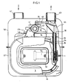
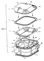
- the counter essentially consists of a sealed external envelope A, a measurement unit B arranged inside the envelope A and a totalizer C which makes it possible to display mechanically the volume measurement made by the measurement unit B.
- the measurement unit B firstly comprises a box D which comprises a central block referenced 1 and two lateral covers respectively referenced 2 and 3.
- the central block, 1 comprises a partition central 1 a arranged along the main longitudinal plane of the central block by a bottom 1 j substantially perpendicular to the central partition 1a, and two side walls referenced 1k.
- the upper part of the central block which is more complex, will be described later.
- the covers 2 and 3 are welded by coupling surfaces forming the edge of the bottom 1j, the side walls 1k and the upper part of the central block 1.
- there are the coupling surfaces 1c and 1d which are welded with coupling surfaces 2a and 3a of the covers 2 and 3.
- each compartment 4 and 5 is separated into two chambers by a deformable bellows or diaphragm.
- the bellows 10 For compartment 4 there is the bellows 10 and for compartment 5 the bellows 11.
- the bellows 11 separates the compartment 5 into a chamber 8 and a chamber 9.
- each bellows is pinched between internal shoulders formed in the bottom 1j, the side walls 1k, and the upper part of the central block 1, respectively referenced 1 e and 1f and flanges respectively referenced 12 and 13.
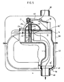
- the box D finally comprises at its upper part a distribution cover 14 which is welded or glued to the upper part of the central block 1 which will be described later.
- the distribution cover 14 and the upper part of the central block 1 further define internal passages respectively referenced 15, 16, 17 and 18. These parts also define a central outlet passage 19 which is better visible in FIGS. 3b and 4.
- the upper face 14b of the distribution cover 14 has four openings or lights each having the shape of a quarter of a circle sector which are respectively referenced 23, 24, 25 and 26 separated by radial bars sealing 14c.
- the upper face 14b forms a seat or window in which the 4 lights are already provided defined.
- the internal passages 15 to 18 are intended to connect each chamber 6 to 9 with one of the lights 23 to 26. More specifically, the chambers 6, 7, 8 and 9 are placed in communication with the lights 23, 24, 25 and 26 , respectively through internal passages 15, 16, 17 and 18.
- FIG. 6e shows that the upper part of the central block 1 comprises an upper wall 1 m into which openings separated by elements of partition parallel to the central partition 1a and which bear the general reference 80. It is on the free upper end of the partition elements 80 that the distribution cover 14 is fixed.
- the orifices form the end of the passages 15 to 19 In FIG. 6e, these orifices have been identified by the reference of the passage whose end they form, but assigned the prime sign.
- the distribution cover 14 has the function of sealingly connecting the orifices 15 ⁇ to 18 ⁇ to the lights 23 to 26.
- Figure 6d shows that the internal passage 17 is reduced to a hole, also referenced 17, drilled in the upper wall 1m of the central block which directly communicates the chamber 8 with the orifice 17 ⁇ and that the internal passage 15 is reduced to a hole, also referenced 15, drilled in the upper wall 1m from the central block and which connects chamber 6 directly with port 15 ⁇ .
- the central passage 19 is limited by a U-shaped partition referenced 82 and the apex of which is connected to the upper periphery of the central partition at least over part of its length, as shown in FIG. 6 a .
- Figure 6b shows that the passage 18 which communicates the chamber 9 with the orifice 18 ⁇ of Figure 6e is limited by an inclined partition 84 connected to the partition elements of Figure 6e surrounding the orifice 18 ⁇ .
- Figure 6c shows that the internal passage 16 which connects the chamber 7 to the Figure 6e 16' orifice is limited by a first inclined wall 86 which extends from the periphery of the central wall 1a through one of the wall elements surrounding the orifice 16 ⁇ , by a second inclined partition 88 separating the passage 16 from part of the orifice 18 ⁇ and by the partition elements of FIG. 6e surrounding the orifice 16 ⁇ .
- FIGS. 6 a to 6e show that, according to an important characteristic of the invention, all of the internal passages 15 to 18, as well as the central passage 19 are defined by structural elements belonging to the block central 1.
- the distribution cover 14 simply has the function of connecting the orifices 15 ⁇ to 18 ⁇ of the block central to the distribution lights 23 to 26.
- the side covers 2 and 3 do not include any element for defining the internal passages.
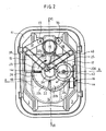
- the measurement unit also includes a rotary distributor bearing the general reference 22.
- the lower face 22 ⁇ of the distributor 22 slides on the seat or glass formed by the upper face 14b of the distribution cover 14. More specifically, the face 14b is provided with bars or ribs 14d, better visible in FIG. 3b, which cooperate with the lower face 22 ⁇ of the dispenser to ensure the necessary seals.
- the dispenser is constituted by four sectors of a circle which consist respectively of an orifice 22c and of a convex zone 22d separated by two flat areas 22b. Each of these four zones corresponds to an angle of 90 °.
- the dispenser also has a recessed central zone 22f which communicates with the hollow convex zone 22d.
- the orifice 22c aims to successively put each light in communication with the outside of the central unit limited by the envelope A, that the convex zone 22nd and the central zone 22f are intended to put in communicating the central passage 19 with one of the lights while isolating the assembly from the outside of the measurement unit and that the flat zones 22b successively close the lights.
- the rotation of the distributor makes it possible to control the admission and the evacuation of the gas in the different measurement chambers.
- crank 21 has a hub 21e provided with a blind hole pivotally mounted on a fixed axis 20 engaged in an axial bore 1 h formed in the central block.
- the crank can thus rotate around the axis 20 which is arranged along the geometric axis of the lights 23 to 26.
- the hub of the crank is also engaged in a sleeve 22e integral with the distributor 22.
- the sleeve 22e is arranged according to the geometric axis of the circular face of the distributor 22 in contact with the face 14b of the distribution cover.
- the 21st hub is engaged This makes it possible to define with better precision the extreme position of the bellows and therefore the useful volume of the chamber.
- the outer shell A consists of two shells 57 and 58 respectively lower and upper.
- the upper shell 58 is provided with a gas inlet nozzle 62 and a gas evacuation nozzle 63.
- the evacuation nozzle 63 is connected by the conduit 64 to the internal evacuation passage 19 by means of the orifice 65 formed in a perforable area 65 ⁇ of the dispensing cover 14 situated outside the surface swept by the dispenser 22.
- the totalizer C visible in FIG. 2 a includes drums 53 for displaying the measurement. These drums are kinematically connected to the wheel 21c of the crank 21 by a set of toothed wheels referenced 41, 43, 45, and 48 which it is not necessary to describe in more detail.
- the distributor 22 is driven in rotation about a variable axis randomly due to the play e which is no longer negligible.
- the movement of the distributor is therefore eccentric relative to the axis of rotation of the hub 21e.
- the contact surface between the bars 14d of the distribution cover and the underside 22 ⁇ of the distributor 22 varies at the same time as the axis of rotation of the distributor. It follows that the wear of the lower face 22 ⁇ of the distributor 22 interests a much larger portion thereof, a portion which is defined by the clearance e . Thus the wear of the face 22 ⁇ of the distributor 22 is much more regular.
- the sets of levers 37-39 and 38-40 may apply to the distributor a tilting torque, as has already been explained.
- this tilting torque is applied to the crank assembly 21. Because there is a certain clearance between the hub 21e of the crank and the sleeve 22e of the distributor, and that the only connection between the crank 21 and the distributor 22 is produced by the tilting cooperation is applied to the crank, but is not transmitted to the distributor itself. As a result, the wear of the face of the dispenser in contact with the glass 14b is regular.
- the gas enters and leaves from the counter to the upper part of the enclosure A.
- the counter is constructed in such a way that, by means of simple machining and assembly operations, the introduction of the gas into the enclosure always at the upper part of the envelope, but that the gas is evacuated at the lower part of the envelope, substantially in the extension of the introduction.
- the central block 1 and the side covers 2 and 3 define an internal passage 19 ⁇ separated, in Figure 4, from the passage 19 by a thin partition 66 perforable.
- the passage 19 ⁇ opens out through the orifice 67 at the lower end of the body D.
- FIG. 6 d shows that the side wall 1k, 1j, 1m of the central block 1 which is connected to the partition 1a, has two coupling surfaces 1c and 1d for fixing the side covers 2 and 3.
- These coupling surfaces 1c and 1d are not entirely flat.
- Each surface has a flat portion 100 corresponding to the bottom of the body 1j and to most of the side faces of the body 1k arranged in a plane parallel to that of the partition 1 a , another portion 102 also planar but arranged in a plane different from that of the portion 100 and parallel to it and corresponding to the upper face 1m on which the distribution cover 14 is fixed, these two flat portions 100 and 102 being connected by two curved portions 104 and 106.
- the curved portions 104 and 106 are generated by a straight portion which moves in parallel to the remaining central partition 1a and perpendicular to the upper face 1m of the central block.
- the central block also defines two shoulders respectively referenced 1e and 1f. These shoulders are planar and arranged symmetrically with respect to the central partition 1a in planes parallel thereto. The plane of each shoulder is internal with respect to the plane in which the first planar portion 100 of the corresponding connection surface is located.
- Each shoulder 1 e , 1 f has pins such as 110 molded with the rest of the central block 1.
- the plane of the shoulder 1 f is disposed between the passage 17 associated with the chamber 8 and the origin of the associated passage 18 in chamber 9. There is a similar arrangement for shoulder 1e.
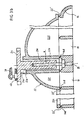
- Figure 7 illustrates the different phases of the installation of the bellows and side covers.
- the end of the arm 72 is pivotally mounted on the plate 30 integral with the bellows 11.
- the flat periphery 112 of the bellows is placed on the shoulder 1f so that the pins 110 penetrate into holes 114 made in the periphery 112 of the bellows.
- the flange 13 is then put in place which is provided with corresponding orifices 116.
- the flange 13 is applied with pressure to the periphery of the bellows and the heads of the nipples 110 are deformed by ultrasound, thereby making a tight fixing of the periphery 112 of the bellows on the shoulder 1f.
- FIG. 7 shows that the side cover 3 has a mating surface 3 a which is conjugate with the mating surface 1d of the central block 1. More specifically, the mating surface has a corresponding flat portion 120 to the portion 100 of the coupling surface 1d, a second planar portion 122 corresponding to the portion 102 and two curved portions 124 and 126 corresponding to the portions 104 and 106 of the surface 1d.
- the side cover 3 comprises a flat part 128 which extends the portion 122 of the coupling surface and an inclined part 130 which connects the flat part 128 to the part 120 of the coupling surface 3 a , this inclined portion 130 being further limited by the curved portions 124 and 126 of the coupling surface 3a.
- the side cover 3 is fixed to the central block 1 by friction welding.
- the cover 3 is placed on the central block 1 in such a way that the coupling surface 3 has cover is in contact with the mating surface 1d of the central block.
- the assembly is subjected: central block 1, lateral cover 3 to a relative vibration movement in the direction F which is perpendicular to the upper part 1m of the central block.
- the combination of the applied force and the relative vibration movement causes localized heating of the coupling surfaces and therefore welding.
- the cover 3 is made of a thermo-plastic material identical to, or compatible with, that of which the central block is made. A sealed connection is thus obtained between the central block 1 and the side cover 3.
- the procedure is similar for mounting the bellows 10 and the side cover 2 respectively on the shoulder 1c and on the coupling surface 1c.
- the heat-sealable material is a polyester butylene terephthalate loaded with glass fibers.
- the pressure exerted perpendicular to the covers is of the order of 700 daN.
- the vibrations applied to the covers in parallel at the coupling surfaces have a frequency of the order of 200 Hz and an amplitude of 0.7 to 1.5 mm.
- the separation between the fixing of the bellows and the fixing of the side covers on the central block makes it possible to considerably simplify the assembly of the meter and to allow its automation, compared with the known techniques according to which the periphery of the bellows is pinched between an edge of the central block and the edge of one of the side covers.
- the bellows it is necessary for the bellows to have an extra thickness at its periphery to ensure double sealing between the bellows, the central block and the side cover.
- the seal since the seal must be produced directly between the central block and the side covers, it is possible to use friction welding which would be impossible if a seal had to be interposed between these two rooms.
- the very shape of the side covers has two advantages over a solution in which the covers are flat.
- the presence of the inclined portion 130 makes it possible to stiffen the cover, on the other hand this same inclined portion makes it possible to reduce the total size of the meter, in particular by authorizing the use of a lower shell 57 which has leave without increasing its dimensions.
Landscapes
- Physics & Mathematics (AREA)
- Fluid Mechanics (AREA)
- General Physics & Mathematics (AREA)
- Measuring Volume Flow (AREA)
- Sampling And Sample Adjustment (AREA)
- Other Investigation Or Analysis Of Materials By Electrical Means (AREA)
- Glass Compositions (AREA)
- Superconductors And Manufacturing Methods Therefor (AREA)
- Gas Separation By Absorption (AREA)
- Acyclic And Carbocyclic Compounds In Medicinal Compositions (AREA)
- Lubrication Details And Ventilation Of Internal Combustion Engines (AREA)
Applications Claiming Priority (3)
| Application Number | Priority Date | Filing Date | Title |
|---|---|---|---|
| FR8309791 | 1983-06-14 | ||
| FR8309791A FR2549221B1 (fr) | 1983-06-14 | 1983-06-14 | Compteur a gaz |
| EP84401196A EP0128838B1 (de) | 1983-06-14 | 1984-06-13 | Gasmesser |
Related Parent Applications (1)
| Application Number | Title | Priority Date | Filing Date |
|---|---|---|---|
| EP84401196.5 Division | 1984-06-13 |
Publications (3)
| Publication Number | Publication Date |
|---|---|
| EP0390934A2 true EP0390934A2 (de) | 1990-10-10 |
| EP0390934A3 EP0390934A3 (en) | 1990-12-27 |
| EP0390934B1 EP0390934B1 (de) | 1994-09-07 |
Family
ID=9289748
Family Applications (2)
| Application Number | Title | Priority Date | Filing Date |
|---|---|---|---|
| EP84401196A Expired EP0128838B1 (de) | 1983-06-14 | 1984-06-13 | Gasmesser |
| EP87117874A Expired - Lifetime EP0390934B1 (de) | 1983-06-14 | 1984-06-13 | Gaszähler |
Family Applications Before (1)
| Application Number | Title | Priority Date | Filing Date |
|---|---|---|---|
| EP84401196A Expired EP0128838B1 (de) | 1983-06-14 | 1984-06-13 | Gasmesser |
Country Status (15)
| Country | Link |
|---|---|
| US (1) | US4593562A (de) |
| EP (2) | EP0128838B1 (de) |
| KR (1) | KR930004083B1 (de) |
| AT (2) | ATE111214T1 (de) |
| BR (1) | BR8402908A (de) |
| DE (2) | DE3479337D1 (de) |
| DK (1) | DK163748C (de) |
| EG (1) | EG16576A (de) |
| ES (2) | ES8601462A1 (de) |
| FR (1) | FR2549221B1 (de) |
| GR (1) | GR82209B (de) |
| IE (1) | IE55254B1 (de) |
| IN (1) | IN165197B (de) |
| MA (1) | MA20149A1 (de) |
| PT (1) | PT78727B (de) |
Cited By (1)
| Publication number | Priority date | Publication date | Assignee | Title |
|---|---|---|---|---|
| WO1999060346A1 (fr) * | 1998-05-20 | 1999-11-25 | Schlumberger Industries S.A. | Procede de fabrication d'un compteur de gaz et compteur de gaz fabrique par un tel procede |
Families Citing this family (10)
| Publication number | Priority date | Publication date | Assignee | Title |
|---|---|---|---|---|
| FR2577164B1 (fr) * | 1985-02-12 | 1987-05-29 | Flonic Sa | Procede de realisation de membranes synthetiques pour compteur a gaz et compteur a gaz comportant une membrane obtenue par la mise en oeuvre dudit procede |
| USD336258S (en) | 1991-12-10 | 1993-06-08 | Schlumberger Industries, Inc. | Gas meter |
| GB9214876D0 (en) * | 1992-07-14 | 1992-08-26 | Smith Meters Ltd | Dry gas meter |
| EP0650581A1 (de) * | 1992-07-14 | 1995-05-03 | Smith Meters Limited | Korper und anschlussmoglichkeiten eines balgen-gaszahlers |
| FR2778981B1 (fr) * | 1998-05-20 | 2000-08-11 | Schlumberger Ind Sa | Compteur de gaz pourvu de moyens de guidage ameliores |
| DE10314638B3 (de) * | 2003-04-01 | 2004-10-07 | Actaris Gaszählerbau GmbH | Balgengaszähler |
| FR2921483B1 (fr) * | 2007-09-25 | 2009-10-23 | Actaris Sas Soc Par Actions Si | Tiroir de distribution pour compteur de gaz a membranes a entrainement de distribution rotatif. |
| FR2921486B1 (fr) * | 2007-09-25 | 2010-03-12 | Actaris Sas | Couvercle de distribution pour compteur de gaz a membranes a entrainement de distribution rotatif. |
| EP2249133B1 (de) | 2009-05-07 | 2019-10-16 | Itron GmbH | Gasmessgerät |
| ES2880344T3 (es) | 2016-09-26 | 2021-11-24 | Itron Inc | Contador modular eficiente alimentado por batería |
Family Cites Families (12)
| Publication number | Priority date | Publication date | Assignee | Title |
|---|---|---|---|---|
| FR539446A (fr) * | 1921-08-17 | 1922-06-26 | Werkstatten Fur Prazisions Mec | Compteur à gaz sec |
| FR1112391A (fr) * | 1953-09-12 | 1956-03-13 | Vivaldi & Compagni | Compteur à gaz |
| FR1122023A (fr) * | 1954-02-02 | 1956-08-30 | Gas Council | Compteur à gaz sec |
| GB857663A (en) * | 1957-01-23 | 1961-01-04 | Continental Sprague Meter Ital | Improvements in or relating to dry gas meters |
| FR1303532A (fr) * | 1961-07-31 | 1962-09-14 | Compteurs Comp D | Compteur de gaz sec à tiroir rotatif |
| US3161049A (en) * | 1962-08-13 | 1964-12-15 | Textron Inc | Gas meter |
| FR1466742A (fr) * | 1965-02-03 | 1967-01-20 | Contigea Sa | Perfectionnements apportés aux compteurs à gaz |
| GB1241796A (en) * | 1967-08-01 | 1971-08-04 | United Gas Industries Ltd | Improvements in dry gas meters |
| BR7209001D0 (pt) * | 1971-12-21 | 1973-08-30 | Galileo Argentina Comercial In | Medidor de gas |
| US4014212A (en) * | 1975-10-08 | 1977-03-29 | The Singer Company | Three-chamber gas meter |
| DE2756163A1 (de) * | 1977-12-16 | 1979-06-21 | Kromschroeder Ag G | Einstueckiger gaszaehlerbauteil |
| US4422324A (en) * | 1981-11-20 | 1983-12-27 | Rockwell International Corporation | Four chamber direct drive gas meter |
-
1983
- 1983-06-14 FR FR8309791A patent/FR2549221B1/fr not_active Expired
-
1984
- 1984-06-07 IE IE1430/84A patent/IE55254B1/en not_active IP Right Cessation
- 1984-06-12 MA MA20373A patent/MA20149A1/fr unknown
- 1984-06-12 DK DK287884A patent/DK163748C/da not_active IP Right Cessation
- 1984-06-12 GR GR74986A patent/GR82209B/el unknown
- 1984-06-12 PT PT78727A patent/PT78727B/pt unknown
- 1984-06-13 AT AT87117874T patent/ATE111214T1/de not_active IP Right Cessation
- 1984-06-13 ES ES533368A patent/ES8601462A1/es not_active Expired
- 1984-06-13 EP EP84401196A patent/EP0128838B1/de not_active Expired
- 1984-06-13 DE DE8484401196T patent/DE3479337D1/de not_active Expired
- 1984-06-13 US US06/620,245 patent/US4593562A/en not_active Expired - Lifetime
- 1984-06-13 EP EP87117874A patent/EP0390934B1/de not_active Expired - Lifetime
- 1984-06-13 EG EG357/84A patent/EG16576A/xx active
- 1984-06-13 AT AT84401196T patent/ATE45423T1/de not_active IP Right Cessation
- 1984-06-13 DE DE3486348T patent/DE3486348T2/de not_active Expired - Lifetime
- 1984-06-14 BR BR8402908A patent/BR8402908A/pt not_active IP Right Cessation
-
1985
- 1985-04-01 ES ES541819A patent/ES8607534A1/es not_active Expired
- 1985-06-05 KR KR1019850003930A patent/KR930004083B1/ko not_active Expired - Lifetime
- 1985-06-06 IN IN417/MAS/85A patent/IN165197B/en unknown
Cited By (3)
| Publication number | Priority date | Publication date | Assignee | Title |
|---|---|---|---|---|
| WO1999060346A1 (fr) * | 1998-05-20 | 1999-11-25 | Schlumberger Industries S.A. | Procede de fabrication d'un compteur de gaz et compteur de gaz fabrique par un tel procede |
| FR2778982A1 (fr) * | 1998-05-20 | 1999-11-26 | Schlumberger Ind Sa | Procede de fabrication d'un compteur de gaz et compteur de gaz fabrique par un tel procede |
| AU757219B2 (en) * | 1998-05-20 | 2003-02-06 | Actaris S.A.S. | Method for making a gas meter and gas meter obtained by said method |
Also Published As
| Publication number | Publication date |
|---|---|
| FR2549221B1 (fr) | 1986-10-31 |
| ES8607534A1 (es) | 1986-05-16 |
| IE55254B1 (en) | 1990-07-18 |
| IN165197B (de) | 1989-08-26 |
| EP0128838B1 (de) | 1989-08-09 |
| GR82209B (de) | 1984-12-13 |
| BR8402908A (pt) | 1985-05-21 |
| ES541819A0 (es) | 1986-05-16 |
| PT78727B (fr) | 1986-07-11 |
| DE3486348D1 (de) | 1994-10-13 |
| FR2549221A1 (fr) | 1985-01-18 |
| DK163748C (da) | 1992-09-07 |
| EP0128838A2 (de) | 1984-12-19 |
| IE841430L (en) | 1984-12-14 |
| KR930004083B1 (ko) | 1993-05-20 |
| MA20149A1 (fr) | 1984-12-31 |
| ES533368A0 (es) | 1985-10-16 |
| DK163748B (da) | 1992-03-30 |
| DK287884A (da) | 1984-12-15 |
| DE3486348T2 (de) | 1995-03-23 |
| US4593562A (en) | 1986-06-10 |
| KR860000542A (ko) | 1986-01-29 |
| ATE45423T1 (de) | 1989-08-15 |
| ATE111214T1 (de) | 1994-09-15 |
| PT78727A (es) | 1985-01-01 |
| DK287884D0 (da) | 1984-06-12 |
| DE3479337D1 (de) | 1989-09-14 |
| ES8601462A1 (es) | 1985-10-16 |
| EP0128838A3 (en) | 1985-11-21 |
| EP0390934B1 (de) | 1994-09-07 |
| EG16576A (en) | 1990-10-30 |
| EP0390934A3 (en) | 1990-12-27 |
Similar Documents
| Publication | Publication Date | Title |
|---|---|---|
| EP0390934B1 (de) | Gaszähler | |
| EP0939893A1 (de) | Miniaturisiertes photoakustisches spektrometer | |
| FR2645259A1 (fr) | Capteur capacitif de deplacements et capteur d'angle de torsion comportant au moins un tel capteur capacitif | |
| EP0018248A1 (de) | Druckwandler mit akustischen Oberflächenwellen und seine Anwendung in dem Zündsystem eines Verbrennungsmotors und in einem Durchflussmessgerät | |
| FR2671149A1 (fr) | Dispositif a rigidite commandee pour la transmission mecanique d'efforts. | |
| FR2666888A1 (fr) | Capteur de mesure d'une grandeur physique. | |
| EP0627614A1 (de) | Zylindrische Messkammer eines Ringkolbenzählers | |
| WO1998035207A1 (fr) | Gyrometre laser triaxial symetrise par rapport a son axe d'activation | |
| CH645698A5 (fr) | Machine a chambres et pistons oscillants. | |
| EP1078229B1 (de) | Gaszähler mit verbesserten führungsmitteln | |
| CH709550A1 (fr) | Capteur de pression différentielle. | |
| EP0075519B1 (de) | Antriebsmechanismus mit Fluidhilfe, insbesondere für Kraftfahrzeugservolenkungssystem | |
| EP0596767B1 (de) | Hydro-elastisches Lager | |
| FR2638587A1 (fr) | Dispositif demontable de support d'un resonateur piezoelectrique a l'interieur d'un boitier | |
| EP1080343B1 (de) | Hestellungsverfahren für einen gaszähler sowie nach einem solchen verfahren hergestellter gaszähler | |
| EP1520128B1 (de) | Anordnung für einen sensor und seine drahtverbindungen in einer mehrplatten-zylinderkopfdichtung aus metall | |
| JPH071187B2 (ja) | ガス・メ−タ | |
| WO1990010791A1 (fr) | Pompe peristaltique | |
| FR2661615A1 (fr) | Regulateur de debit pour dispositif servant a administrer a un patient un liquide, par gravite. | |
| FR2897129A1 (fr) | Verin et systeme de frein pour vehicule automobile. | |
| EP2161789A1 (de) | Modularerer Adapter für Anschlusseinsatz und mit solchen modularen Adaptern ausgestattete Anschlusseinheit | |
| EP2207017A1 (de) | Volumetrisches Messgerät mit zwei Kolben für eine Kraftstoff-Abgabevorrichtung | |
| WO1996004538A1 (fr) | Dispositif de mesure de la pression en differents points de mesure | |
| WO2002071102A2 (fr) | Element de maintien et d'indexation d'une structure guidante asymetrique | |
| CH231548A (fr) | Machine à piston oscillant. |
Legal Events
| Date | Code | Title | Description |
|---|---|---|---|
| PUAI | Public reference made under article 153(3) epc to a published international application that has entered the european phase |
Free format text: ORIGINAL CODE: 0009012 |
|
| AC | Divisional application: reference to earlier application |
Ref document number: 128838 Country of ref document: EP |
|
| AK | Designated contracting states |
Kind code of ref document: A2 Designated state(s): AT BE DE GB IT NL SE |
|
| PUAL | Search report despatched |
Free format text: ORIGINAL CODE: 0009013 |
|
| AK | Designated contracting states |
Kind code of ref document: A3 Designated state(s): AT BE DE GB IT NL SE |
|
| RHK1 | Main classification (correction) |
Ipc: G01F 15/16 |
|
| 17P | Request for examination filed |
Effective date: 19910618 |
|
| 17Q | First examination report despatched |
Effective date: 19930408 |
|
| GRAA | (expected) grant |
Free format text: ORIGINAL CODE: 0009210 |
|
| AC | Divisional application: reference to earlier application |
Ref document number: 128838 Country of ref document: EP |
|
| AK | Designated contracting states |
Kind code of ref document: B1 Designated state(s): AT BE DE GB IT NL SE |
|
| PG25 | Lapsed in a contracting state [announced via postgrant information from national office to epo] |
Ref country code: GB Effective date: 19940907 |
|
| REF | Corresponds to: |
Ref document number: 111214 Country of ref document: AT Date of ref document: 19940915 Kind code of ref document: T |
|
| REF | Corresponds to: |
Ref document number: 3486348 Country of ref document: DE Date of ref document: 19941013 |
|
| ITF | It: translation for a ep patent filed | ||
| EAL | Se: european patent in force in sweden |
Ref document number: 87117874.5 |
|
| GBV | Gb: ep patent (uk) treated as always having been void in accordance with gb section 77(7)/1977 [no translation filed] |
Effective date: 19940907 |
|
| PGFP | Annual fee paid to national office [announced via postgrant information from national office to epo] |
Ref country code: SE Payment date: 19950522 Year of fee payment: 12 |
|
| PGFP | Annual fee paid to national office [announced via postgrant information from national office to epo] |
Ref country code: AT Payment date: 19950629 Year of fee payment: 12 |
|
| PGFP | Annual fee paid to national office [announced via postgrant information from national office to epo] |
Ref country code: BE Payment date: 19950707 Year of fee payment: 12 |
|
| PLBE | No opposition filed within time limit |
Free format text: ORIGINAL CODE: 0009261 |
|
| STAA | Information on the status of an ep patent application or granted ep patent |
Free format text: STATUS: NO OPPOSITION FILED WITHIN TIME LIMIT |
|
| 26N | No opposition filed | ||
| PG25 | Lapsed in a contracting state [announced via postgrant information from national office to epo] |
Ref country code: AT Effective date: 19960613 |
|
| PG25 | Lapsed in a contracting state [announced via postgrant information from national office to epo] |
Ref country code: SE Effective date: 19960614 |
|
| PG25 | Lapsed in a contracting state [announced via postgrant information from national office to epo] |
Ref country code: BE Effective date: 19960630 |
|
| BERE | Be: lapsed |
Owner name: SCHLUMBERGER INDUSTRIES Effective date: 19960630 |
|
| EUG | Se: european patent has lapsed |
Ref document number: 87117874.5 |
|
| PGFP | Annual fee paid to national office [announced via postgrant information from national office to epo] |
Ref country code: DE Payment date: 20030626 Year of fee payment: 20 |
|
| PGFP | Annual fee paid to national office [announced via postgrant information from national office to epo] |
Ref country code: NL Payment date: 20030630 Year of fee payment: 20 |
|
| PG25 | Lapsed in a contracting state [announced via postgrant information from national office to epo] |
Ref country code: NL Free format text: LAPSE BECAUSE OF EXPIRATION OF PROTECTION Effective date: 20040613 |
|
| NLV7 | Nl: ceased due to reaching the maximum lifetime of a patent |
Effective date: 20040613 |