EP0391703A2 - Calculateurs et isolateurs optiques quasi-achromatiques utilisant des prismes à réflexion totale interne - Google Patents
Calculateurs et isolateurs optiques quasi-achromatiques utilisant des prismes à réflexion totale interne Download PDFInfo
- Publication number
- EP0391703A2 EP0391703A2 EP90303641A EP90303641A EP0391703A2 EP 0391703 A2 EP0391703 A2 EP 0391703A2 EP 90303641 A EP90303641 A EP 90303641A EP 90303641 A EP90303641 A EP 90303641A EP 0391703 A2 EP0391703 A2 EP 0391703A2
- Authority
- EP
- European Patent Office
- Prior art keywords
- degrees
- wavelength
- light beam
- prisms
- optical
- Prior art date
- Legal status (The legal status is an assumption and is not a legal conclusion. Google has not performed a legal analysis and makes no representation as to the accuracy of the status listed.)
- Withdrawn
Links
Images

Classifications
-
- G—PHYSICS
- G02—OPTICS
- G02F—OPTICAL DEVICES OR ARRANGEMENTS FOR THE CONTROL OF LIGHT BY MODIFICATION OF THE OPTICAL PROPERTIES OF THE MEDIA OF THE ELEMENTS INVOLVED THEREIN; NON-LINEAR OPTICS; FREQUENCY-CHANGING OF LIGHT; OPTICAL LOGIC ELEMENTS; OPTICAL ANALOGUE/DIGITAL CONVERTERS
- G02F1/00—Devices or arrangements for the control of the intensity, colour, phase, polarisation or direction of light arriving from an independent light source, e.g. switching, gating or modulating; Non-linear optics
- G02F1/01—Devices or arrangements for the control of the intensity, colour, phase, polarisation or direction of light arriving from an independent light source, e.g. switching, gating or modulating; Non-linear optics for the control of the intensity, phase, polarisation or colour
- G02F1/09—Devices or arrangements for the control of the intensity, colour, phase, polarisation or direction of light arriving from an independent light source, e.g. switching, gating or modulating; Non-linear optics for the control of the intensity, phase, polarisation or colour based on magneto-optical elements, e.g. exhibiting Faraday effect
- G02F1/093—Devices or arrangements for the control of the intensity, colour, phase, polarisation or direction of light arriving from an independent light source, e.g. switching, gating or modulating; Non-linear optics for the control of the intensity, phase, polarisation or colour based on magneto-optical elements, e.g. exhibiting Faraday effect used as non-reciprocal devices, e.g. optical isolators, circulators
-
- G—PHYSICS
- G02—OPTICS
- G02F—OPTICAL DEVICES OR ARRANGEMENTS FOR THE CONTROL OF LIGHT BY MODIFICATION OF THE OPTICAL PROPERTIES OF THE MEDIA OF THE ELEMENTS INVOLVED THEREIN; NON-LINEAR OPTICS; FREQUENCY-CHANGING OF LIGHT; OPTICAL LOGIC ELEMENTS; OPTICAL ANALOGUE/DIGITAL CONVERTERS
- G02F2203/00—Function characteristic
- G02F2203/04—Function characteristic wavelength independent
Definitions
- This application pertains generally to the field of nonreciprocal optical devices such as optical isolators and optical circulators, which are constructed from materials that exhibit the optical Faraday effect.
- Optical isolators are commonly used to overcome the instability in semiconductor light sources caused by reflected light.
- Optical circulators may be used in two-way fiber optic communication systems and in other applications.
- this application pertains to quasi-achromatic isolators and circulators using total internal Fresnel reflection to simplify their construction.
- Nonreciprocal optical devices such as isolators and circulators may be constructed from materials that exhibit the optical Faraday effect.
- This effect is a circular birefringence that arises from the presence within the material of a magnetization resulting from an externally applied magnetic field or from an internal spontaneous magnetization due to ferromagnetic or ferrimagnetic ordering that may be held in a saturated state by an externally applied magnetic field. In either case, it manifests itself as an optical rotatory effect upon light propagating through the material along the direction of magnetization. It is nonreciprocal in that the sense of rotation of the axes of polarization depends on the polarity of the magnetization relative to the direction of propagation.
- Optical signals transmitted through fiber optic waveguides are being used for telecommunications to an ever increasing extent. They are generated by laser diodes of various types that often operate at wavelengths in the 1.28 to 1.60 ⁇ range. Some of these lasers, especially those of the so-called distributed feedback construction, are somewhat sensitive to light returning on their output fiber whether it be from reflections of their own emissions or from another source.
- An optical isolator which is a nonreciprocal two port device that passes light in one direction and absorbs light in the opposite direction, is often necessary to obtain optimum operation from these laser diode sources.
- the optical circulator is a more generally applicable nonreciprocal four port device. As with the isolator, light entering the first port passes out the second port, but light entering the second port is not absorbed, and instead passes out the third port. Similarly, light entering the third port passes out the fourth port, and light entering the fourth port passes out the first port.
- a circulator can function as an isolator, but it also has the potential of permitting optical fiber transmission lines to be operated in a bidirectional mode with signals at the same or different wavelengths traveling in opposite directions simultaneously.
- the 45° Faraday rotation element which is usually composed of glass or a single crystal transparent over the desired wavelength range.
- Opposing parallel optical facets surround the active region which is within an externally applied axial magnetic field provided by adjacent permanent magnets or by a current carrying solenoid.
- the field strength required to obtain 45° of rotation depends on the Verdet constant of the element material.
- Suitable materials include diamagnetic glasses especially those with a high lead oxide content, paramagnetic glasses or cubic crystals containing ions such as trivalent cerium or terbium, and ferrimagnetic oxide crystals such as yttrium iron garnet.
- the latter commonly known as YIG, is especially useful in the 1.28 ⁇ to 1.60 ⁇ wavelength range where many optical fiber systems operate.
- an optical isolator In its simplest form an optical isolator consists of an input plane polarizer, a 45° Faraday element with its associated axial field magnet, and an output plane polarizer with its polarization axis rotationally orientated at 45° relative to that of the input polarizer.
- a compact isolator of this type using a YIG crystal has been described in the literature. Input light must be plane polarized to pass through the input polarizer after which its plane of polarization is rotated 45° by the Faraday element so that it can pass through the output polarizer. If the propagation direction is reversed, the Faraday element will rotate -45° and the light passed through it will be absorbed in the output polarizer.
- a similar optical circulator, also using a YIG crystal, but with input and output polarization beam splitters instead of plane polarizers has also been described in the literature. Both devices require specific states of plane polarization at their ports to function optimally.
- the degree of isolation obtainable with either of these nonreciprocal devices is limited by deviations of the Faraday element rotation from its nominal 45°.
- the element is designed for some nominal wavelength, and in general it will have a greater rotation at shorter and a lesser rotation at longer wavelengths.
- some Faraday elements such as YIG are temperature sensitive so the rotation will change due to temperature variations.
- Various techniques have been used to improve the degree of isolation by minimizing these deviations from 45° rotation. In the case of YIG, gadolinium substitution for part of the yttrium lowers the temperature coefficient of the rotation, but at the expense of its magnitude.
- the wavelength dependence can be partially compensated by a second element have -45° of reciprocal type rotation. Such an element can be made from an optically active crystal.
- the two-element combination between crossed polarizers would be used as an isolator.
- the opposite rotations would always sum to zero if they had identical wavelength dependences. But for the opposite direction of propagation both elements would have -45° of rotation which would sum to -90° with a doubled wavelength variation.
- the isolator would therefore have a wavelength dependent insertion loss.
- the cross-referenced European application discloses a quasi-achromatic configuration of two Faraday elements and five birefringent plates which when suitably oriented between two linearly polarizing elements would constitute an optical isolator or circulator.
- the nominal Faraday rotations of the two elements are 45° and 90° at a center design wavelength about which the devices are to operate. Changes in these rotations due to either wavelength or temperature variations compensate one another because of their coupling by the birefringent plates. In this way a higher degree of isolation is obtained over a wider optical bandwidth than would be possible in a device using a single 45° Faraday element.
- a group of three plates is used between the two Faraday elements and two more follow them to give the required polarization transformations which must themselves be quasi-achromatic over the desired wavelength range.
- the present invention provides an optical configuration of two nonreciprocal Faraday elements coupled by linear retardation elements based on total internal Fresnel reflection such that wavelength or temperature effects on the Faraday elements compensate one another to give quasi-achromatic isolation and/or temperature stability when this optical configuration is incorporated into an optical isolator or circulator.
- a nonreciprocal optical wavelength filter through which a light beam within a wavelength range can propagate consists of an input polarization filter, through which the beam enters said filter, an alternating sequence of wavelength dependent nonreciprocal circularly birefringent elements and wavelength in dependent linear retardation elements, through which the beam is propagated, and an output polarization filter through which said beam exits the filter.
- a quasi-achromatic optical isolator through which a light beam within a wavelength range about a nominal wavelength may propagate is made from a sequence of elements having a first plane polarizer accepting said light beam as an input, said light beam then passing through in sequence, a first Faraday rotator, a first wavelength independent linear retardation element, a second Faraday rotator, a second wavelength independent linear retardation element, and said light beam exiting said isolator undiminished in intensity through a second plane polarizer.
- a quasi-achromatic optical circulator having first, second, third and fourth ports is provided such that said circulator may accept a light beam within a wavelength range about a nominal wavelength and direct it to a succeeding port.
- a light beam enters said circulator through a first polarizing beam splitter adjacent to said first and third ports and passes through sequentially a first Faraday rotator, a first wavelength independent linear retardation element, a second Faraday rotator, a second wavelength independent linear retardation element and a second polarizing beam splitter adjacent to said second and fourth ports of said circulator, whereby said light beam is transmitted undiminished in intensity to the next succeeding port.
- said wavelength independent linear retardation elements of said isolator and circulator are optically transparent isotropic prisms within which said beam undergoes total internal reflection.
- said first and second prisms have refractive indicies between 1.69 and 1.81 and said light beam is deflected 90 degrees by total internal reflection at an angle of incidence of 45 degrees within said first and second prisms in a common plane of incidence parallel to the x axis whereby said light beam experiences linear retardations between 58 and 64 degrees with fast axes parallel to the x axis within said prisms.
- This application pertains generally to the field of nonreciprocal optical devices such as optical isolators and optical circulators, which are constructed from materials that exhibit the optical Faraday effect.
- Optical isolators are commonly used to overcome the instability in semiconductor light sources caused by reflected light.
- Optical circulators may be used in two-way fiber optic communication systems and in other applications.
- this application pertains to quasi-achromatic isolators and circulators using total internal Fresnel reflection to simplify their construction.
- the basic prior art nonreciprocal configuration of an optical isolator uses a single 45° Faraday element, as shown in Figs 1.
- An input light beam 12 propagates along the +z axis in a right hand coordinate system and passes in turn through plane polarizer 14, Faraday rotation element 15, and output plane polarizer 18.
- Beam 12 is plane polarized at an angle of 0° to the x axis and passes through polarizer 14 unchanged.
- Faraday rotation element 15 which includes its axial field producing magnet, the plane of polarization is rotated to an angle of +45° from the x axis.
- Output polarizer 18 is oriented at +45° to pass beam 12 undiminished in intensity.
- a reverse direction beam would initially be polarized at +45° so as to pass through polarizer 18 unchanged.
- the polarization direction of the beam would be rotated to an angle of +90° so that it would be completely absorbed by polarizer 14.
- the device functions as an isolator because it transmits light propagating in the +z direction and absorbs light propagating in the -z direction.
- a rotator element is considered to have a positive rotation if the polarization axes rotate in a counterclockwise direction as the oncoming light beam is observed.
- the polarization axes were rotated from x toward y for both propagation directions, but according to the above definition this corresponds to a +45° rotation for the +z direction and a -45° rotation for the -z direction. This is the behavior of the Faraday effect.
- a reciprocal rotation element on the other hand has the same polarity of rotation for both propagation directions. Light propagating in an optically active element, for example, would have its polarization axes rotated, but if the direction of propagation were reversed the polarization axes would retrace the orientations traced during their forward path.
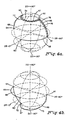
- equatorial points represent linear polarization states with the optical electric field orientation varying from 0° to 180°.
- the north and south poles represent right and left circular polarization states respectively, while all other points represent states of elliptical polarization.
- This Poincare sphere representation results from the fact that a polarization transformation produced by a birefringent element is represented by a circular path around an axis representing the principal polarization modes of the element.
- Linearly birefringent plates for example, produce polarization transformations represented on the sphere by circular arcs around equatorial axes, while circularly birefringent elements such as reciprocal or nonreciprocal rotators produce polarization transformations represented on the sphere by circular arcs around the polar axis.
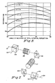
- FIG. 2 An isolator constructed according to the present invention is shown in Fig. 2.
- Input light beam 22 propagates along the +z axis in a right hand coordinate system and passes in turn through plane polarizer 24, Faraday rotation element 25, reflecting prism 26, Faraday rotation element 27, reflecting prism 28, and output plane polarizer 29.
- Beam 22 is plane polarized at an angle of 0° to the x axis and passes through polarizer 24 unchanged.
- Faraday rotation element 25 which includes its axial field producing magnet
- the second Faraday rotation element 27, which also includes its axial field producing magnet has a rotation angle of -90°.
- Output polarizer 29 is oriented at +135° from the x axis.
- Input light beam 52 propagates along the +z axis in a right hand coordinate system and passes in turn through plane polarizer 54, Faraday rotation element 55, linearly birefringent plate 56, Faraday rotation element 57, birefringent plate 58 and output plane polarizer 59.
- Beam 52 is plane polarized at an angle of 0° to the x axis and passes through polarizer 54 unchanged.
- Faraday rotation elements 55 and 57 have rotations of +45 and -90°, respectively, obtained by oppositely orienting their associated axial field magnets relative to the beam direction, and plates 56 and 58 have retardations of +60° with their fast axes oriented at +90° from the x axis.
- the polarization transformations that take place in elements 55, 56, 57, and 58 are represented on the Poincare sphere diagram of Fig. 4a (Fig. 6a in the cross-referenced European application) in terms of the spherical coordinates 2 ⁇ and 2 ⁇ , where ⁇ is the orientation of the major elliptic axis and ⁇ is the ellipticity. The latter is the arc tangent of the elliptic axis ratio and is 45° for circularly polarized light.
- the radii of +90 and -180° arcs and 65 and 67 of Fig. 4a are proportional to the cosines of their 2 ⁇ values which are 0° and 60° respectively. Since the radius of the -180° arc is half that of the +90° arc. the arc lengths are equal but opposite in sense. If the Faraday rotations that they represent each change by a proportional amount due to wavelength or temperature variations, the lengths of arcs 65 and 67 will both change by equal amounts.
- Arc 65 represents the nominal +45° Faraday rotation by element 55 from the input linear polarization state at point 60 to point 61.
- a change in its length causes the following +60° arc 66 which represents the transformation by plate 56 to move to a new position 76 or 78 while remaining centered about an equatorial axis through point 60.
- Both endpoints of arc 66 move by equal distances, and so the equal change in the length of arc 67 compensates that of arc 65, thereby leaving endpoint 63 of arc 67 representing the -90° Faraday rotation by element 57 invariant.
- Proportional changes in the retardations of plates 56 and 58 due to temperature or wavelength variations will cause the lengths of arcs 66 and 68 to change by equal amounts.
- Output polarizer 59 is oriented at +135° to pass beam 52 undiminished in intensity.
- the operation of the isolator of Fig. 3 in the reverse direction is equivalent to reversing the polarity of both Faraday rotators.
- the polarization transformations are then represented by the Poincare sphere diagram of Fig. 4b (Fig. 6b of the cross-referenced application).
- Output polarizer 59 oriented at +135 degrees completely absorbs beam 52.
- each birefringent plate of Fig. 3 is replaced by the optical retardation between linear polarization states obtained from the differential phase shift accompanying total internal Fresnel reflection in prisms 26 and 28.
- Beam 22 enters and leaves prisms 26 and 28 at normal incidence, but is reflected internally at a 45 degree angle of incidence by the uncoated hypotenuse face of the 45° right angle prisms.
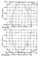
- the retardations obtainable within a right angle prism are shown in Fig. 5.
- the prisms from glass having an index of refraction between 1.69 and 1.81 retardations between 58° and 64° may be obtained that are insensitive to the angle of incidence near 45°. Wavelength affects the retardation only by virtue of the small dispersion of the index of refraction of the glass.
- Fig. 6a shows the forward transmission of the single Faraday element isolator of Fig. 1 as curve 30 while curve 32 shows the forward transmission of the present invention of Fig. 2.
- Fig. 6b shows the reverse transmission of the same two isolators as curves 31 and 33 respectively. These functions determine the degree of optical isolation attainable. Curve 33 remains below 0.0005 within the 1.28 ⁇ to 1.60 ⁇ wavelength range and this represents an isolation of -33dB. Within the same range curve 31 of the single Faraday element isolator reaches 0.017 transmission for an isolation of only -17.7 dB.
- a circulator may be derived from the isolator of Fig. 2 by replacing polarizers 24 and 29 by polarizing beam splitters 44 and 49 as shown in Fig. 7.
- Each may be a glass cube prism with a diagonal interface containing a multilayer dielectric coating that reflects the TE and transits the TM polarization states.
- the four input and/or output beams 51, 52, 53, and 54 are the four ports of the circulator and beams entering each port must be plane polarized for proper operation.
Landscapes
- Physics & Mathematics (AREA)
- Nonlinear Science (AREA)
- Engineering & Computer Science (AREA)
- Power Engineering (AREA)
- General Physics & Mathematics (AREA)
- Optics & Photonics (AREA)
Applications Claiming Priority (2)
| Application Number | Priority Date | Filing Date | Title |
|---|---|---|---|
| US07/335,146 US4991938A (en) | 1989-04-07 | 1989-04-07 | Quasi-achromatic optical isolators and circulators using prisms with total internal fresnel reflection |
| US335146 | 1994-11-07 |
Publications (2)
| Publication Number | Publication Date |
|---|---|
| EP0391703A2 true EP0391703A2 (fr) | 1990-10-10 |
| EP0391703A3 EP0391703A3 (fr) | 1991-08-21 |
Family
ID=23310469
Family Applications (1)
| Application Number | Title | Priority Date | Filing Date |
|---|---|---|---|
| EP19900303641 Withdrawn EP0391703A3 (fr) | 1989-04-07 | 1990-04-04 | Calculateurs et isolateurs optiques quasi-achromatiques utilisant des prismes à réflexion totale interne |
Country Status (4)
| Country | Link |
|---|---|
| US (1) | US4991938A (fr) |
| EP (1) | EP0391703A3 (fr) |
| JP (1) | JPH02287421A (fr) |
| CA (1) | CA2011829A1 (fr) |
Cited By (1)
| Publication number | Priority date | Publication date | Assignee | Title |
|---|---|---|---|---|
| CN100516980C (zh) * | 2006-09-14 | 2009-07-22 | 武汉光迅科技股份有限公司 | 多端口闭路光环行器 |
Families Citing this family (28)
| Publication number | Priority date | Publication date | Assignee | Title |
|---|---|---|---|---|
| DE69121176T2 (de) * | 1990-12-17 | 1997-01-09 | Nippon Telegraph & Telephone | Optischer Zirkulator |
| JP2677726B2 (ja) * | 1991-09-20 | 1997-11-17 | 富士通株式会社 | 光送信機 |
| US5212586A (en) * | 1991-11-26 | 1993-05-18 | Optics For Research | Optical circulator having a simplified construction |
| JPH06222212A (ja) * | 1992-12-03 | 1994-08-12 | Matsushita Electric Ind Co Ltd | 偏波面回転光学装置及び偏光変換光学装置及び投写型表示装置 |
| US5657151A (en) * | 1993-12-09 | 1997-08-12 | Lucent Technologies Inc. | Polarization scrambler/modulator |
| US5404413A (en) * | 1993-12-14 | 1995-04-04 | At&T Corp. | Optical circulator for dispersion compensation |
| US5689593A (en) * | 1995-10-13 | 1997-11-18 | E-Tek Dynamics, Inc. | Compact fiberoptic circulator with low polarization mode dispersion |
| US5682446A (en) * | 1995-10-13 | 1997-10-28 | E-Tek Dynamics, Inc. | Polarization mode dispersion-free circulator |
| US6075596A (en) | 1998-05-19 | 2000-06-13 | E-Tek Dynamics, Inc. | Low cost fiber optic circulator |
| US6154581A (en) * | 1998-10-27 | 2000-11-28 | Adc Telecommunications, Inc. | Multiple port, fiber optic circulator |
| GB2344238B (en) * | 1998-11-28 | 2001-02-21 | Marconi Comm Ltd | Photonics system |
| US6246807B1 (en) | 1999-04-06 | 2001-06-12 | Adc Telecommunications, Inc. | Optical circulator |
| US6407861B1 (en) | 1999-04-06 | 2002-06-18 | Adc Telecommunications, Inc. | Adjustable optical circulator |
| US6961179B2 (en) * | 2001-11-30 | 2005-11-01 | Colorlink, Inc. | Compensated color management systems and methods |
| US7002752B2 (en) * | 2001-11-30 | 2006-02-21 | Colorlink, Inc. | Three-panel color management systems and methods |
| US6816309B2 (en) * | 2001-11-30 | 2004-11-09 | Colorlink, Inc. | Compensated color management systems and methods |
| US6943881B2 (en) * | 2003-06-04 | 2005-09-13 | Tomophase Corporation | Measurements of optical inhomogeneity and other properties in substances using propagation modes of light |
| US8498681B2 (en) * | 2004-10-05 | 2013-07-30 | Tomophase Corporation | Cross-sectional mapping of spectral absorbance features |
| US7970458B2 (en) * | 2004-10-12 | 2011-06-28 | Tomophase Corporation | Integrated disease diagnosis and treatment system |
| US20060197914A1 (en) * | 2005-03-04 | 2006-09-07 | Colorlink, Inc. | Four panel projection system |
| US7831298B1 (en) | 2005-10-04 | 2010-11-09 | Tomophase Corporation | Mapping physiological functions of tissues in lungs and other organs |
| JP2007178409A (ja) * | 2005-12-28 | 2007-07-12 | Topcon Corp | 光画像計測装置 |
| US7706646B2 (en) * | 2007-04-24 | 2010-04-27 | Tomophase Corporation | Delivering light via optical waveguide and multi-view optical probe head |
| WO2009108950A2 (fr) * | 2008-02-29 | 2009-09-03 | Tomophase Corporation | Mise en correspondance de profils de température et thermothérapie guidée |
| US8467858B2 (en) * | 2009-04-29 | 2013-06-18 | Tomophase Corporation | Image-guided thermotherapy based on selective tissue thermal treatment |
| EP2470886A4 (fr) | 2009-08-26 | 2016-11-02 | Tomophase Inc | Imagerie optique tissulaire basée sur l'imagerie optique dans le domaine des fréquences |
| CN108594426B (zh) * | 2018-01-30 | 2023-06-30 | 中国工程物理研究院激光聚变研究中心 | 一种光延迟器及其使用方法 |
| CN110440693B (zh) * | 2019-08-27 | 2022-04-01 | 上海航天计算机技术研究所 | 一种准光馈电网络系统及误差测试方法 |
Family Cites Families (10)
| Publication number | Priority date | Publication date | Assignee | Title |
|---|---|---|---|---|
| NL6715244A (fr) * | 1967-11-09 | 1969-05-13 | ||
| JPS55121215U (fr) * | 1979-02-21 | 1980-08-28 | ||
| DE3327417A1 (de) * | 1983-07-29 | 1985-02-07 | Philips Patentverwaltung Gmbh, 2000 Hamburg | Optische verzweigungsvorrichtung |
| JPS60130934A (ja) * | 1983-12-20 | 1985-07-12 | Fujitsu Ltd | 光アイソレ−タ |
| JPS60202415A (ja) * | 1984-03-27 | 1985-10-12 | Hoya Corp | 光アイソレ−タ |
| US4762384A (en) * | 1985-04-29 | 1988-08-09 | American Telephone And Telegraph Company, At&T Bell Laboratories | Optical systems with antireciprocal polarization rotators |
| US4671613A (en) * | 1985-11-12 | 1987-06-09 | Gte Laboratories Inc. | Optical beam splitter prism |
| JPS6317426A (ja) * | 1986-07-09 | 1988-01-25 | Nec Corp | 光アイソレ−タ |
| DE3884421T2 (de) * | 1987-02-17 | 1994-02-03 | Hitachi Metals Ltd | Optischer Isolator. |
| JPS63228121A (ja) * | 1987-03-17 | 1988-09-22 | Seiko Instr & Electronics Ltd | 光フアイバ光アイソレ−タ |
-
1989
- 1989-04-07 US US07/335,146 patent/US4991938A/en not_active Expired - Lifetime
-
1990
- 1990-03-09 CA CA002011829A patent/CA2011829A1/fr not_active Abandoned
- 1990-03-28 JP JP2077163A patent/JPH02287421A/ja active Pending
- 1990-04-04 EP EP19900303641 patent/EP0391703A3/fr not_active Withdrawn
Cited By (1)
| Publication number | Priority date | Publication date | Assignee | Title |
|---|---|---|---|---|
| CN100516980C (zh) * | 2006-09-14 | 2009-07-22 | 武汉光迅科技股份有限公司 | 多端口闭路光环行器 |
Also Published As
| Publication number | Publication date |
|---|---|
| JPH02287421A (ja) | 1990-11-27 |
| EP0391703A3 (fr) | 1991-08-21 |
| US4991938A (en) | 1991-02-12 |
| CA2011829A1 (fr) | 1990-10-07 |
Similar Documents
| Publication | Publication Date | Title |
|---|---|---|
| US4991938A (en) | Quasi-achromatic optical isolators and circulators using prisms with total internal fresnel reflection | |
| US4988170A (en) | Quasi-achromatic optical isolators and circulators | |
| US5204771A (en) | Optical circulator | |
| US5212586A (en) | Optical circulator having a simplified construction | |
| US5682446A (en) | Polarization mode dispersion-free circulator | |
| EP0525208B1 (fr) | Isolateur optique | |
| CA1149499A (fr) | Circulateur optique | |
| US6757101B2 (en) | None-mechanical dual stage optical switches | |
| US6931165B2 (en) | Variable polarization plane rotator and optical device using same | |
| JPH07218866A (ja) | 光アイソレータ | |
| US6876480B2 (en) | Farady rotation device and optical device comprising it | |
| US5078512A (en) | Unidirectional mode converter and optical isolator using same | |
| JPS61264301A (ja) | 直線偏光の偏光面回転装置及びその製造方法 | |
| JP2542532B2 (ja) | 偏光無依存型光アイソレ―タの製造方法 | |
| JPH07191280A (ja) | 光学アイソレータ | |
| JPS63200117A (ja) | 多段光アイソレ−タ | |
| JPH0244310A (ja) | 光アイソレータ | |
| JP2516463B2 (ja) | 偏光無依存型光アイソレ―タ | |
| Yan et al. | Magneto‐optic circulator for optical fiber transmission | |
| JP2567697B2 (ja) | ファラデー回転装置 | |
| CN100549766C (zh) | 微型磁光开关 | |
| CN101672985A (zh) | 一种磁光开关 | |
| JPH07191279A (ja) | 光学アイソレータ | |
| JPH04264515A (ja) | 光アイソレータ | |
| JP2002250897A (ja) | 光デバイス |
Legal Events
| Date | Code | Title | Description |
|---|---|---|---|
| PUAI | Public reference made under article 153(3) epc to a published international application that has entered the european phase |
Free format text: ORIGINAL CODE: 0009012 |
|
| AK | Designated contracting states |
Kind code of ref document: A2 Designated state(s): BE DE FR GB NL |
|
| PUAL | Search report despatched |
Free format text: ORIGINAL CODE: 0009013 |
|
| AK | Designated contracting states |
Kind code of ref document: A3 Designated state(s): BE DE FR GB NL |
|
| STAA | Information on the status of an ep patent application or granted ep patent |
Free format text: STATUS: THE APPLICATION IS DEEMED TO BE WITHDRAWN |
|
| 18D | Application deemed to be withdrawn |
Effective date: 19920222 |