EP0392825A2 - Dokumentenverarbeitungsapparat - Google Patents
Dokumentenverarbeitungsapparat Download PDFInfo
- Publication number
- EP0392825A2 EP0392825A2 EP90303918A EP90303918A EP0392825A2 EP 0392825 A2 EP0392825 A2 EP 0392825A2 EP 90303918 A EP90303918 A EP 90303918A EP 90303918 A EP90303918 A EP 90303918A EP 0392825 A2 EP0392825 A2 EP 0392825A2
- Authority
- EP
- European Patent Office
- Prior art keywords
- information
- flow
- data
- maximum
- input
- Prior art date
- Legal status (The legal status is an assumption and is not a legal conclusion. Google has not performed a legal analysis and makes no representation as to the accuracy of the status listed.)
- Granted
Links
Images









Classifications
-
- G—PHYSICS
- G06—COMPUTING OR CALCULATING; COUNTING
- G06F—ELECTRIC DIGITAL DATA PROCESSING
- G06F40/00—Handling natural language data
- G06F40/10—Text processing
- G06F40/166—Editing, e.g. inserting or deleting
- G06F40/177—Editing, e.g. inserting or deleting of tables; using ruled lines
Definitions
- Fig. t is a schematic block diagram showing an arrangement of a control unit of an English word processor according to an embodiment of the present invention.
- a keyboard (KB) 1 is connected to a keyboard interface (KB I/F) 2.
- KB I/F 2 receives a key code from the KB 1, and outputs it onto a CPU bus 7.
- the CPU bus 7 is connected to a program ROM 3, a dictionary ROM 4, a dictionary RAM 5, and a CPU 6.
- the program ROM 3 stores control programs for the CPU 6, various data, and the like.
- the dictionary ROM 4 stores a spelling check word dictionary.
- the dictionary RAM 5 is used by a user to register, as a dictionary, character strings, e.g., person's names which may be found to require correction during spelling checking.
- the CPU 6 executes various control process operations according to the control programs stored in the program ROM 3.
- the CPU bus 7 includes an address bus, a data bus, and a control bus.
- the CPU bus 7 is also connected to a CRT controller (CRTC) 8 and a RAM 9.
- the CRTC 8 is connected to a display (CRT) 13.
- the CRTC 8 causes the CRT 13 to display bit map data stored in the RAM 9 in accordance with an instruction from the CPU 6.
- the RAM 9 stores document information input from the KB 1, and also stores display information to be displayed on the CRT 13 in the bit map format.
- the CRT 13 displays display information from the RAM 9 under the control of the CRTC 8.
- the CRTC 8 is also connected to a CRT interface (CRT I/F) 14.
- the CRT I/F 14 receives signals from the CRTC 8 and the RAM 9, and displays them on the CRT 13.
- An external storage 15 such as a hard disc or floppy disc unit stores input document information through a disc interface (DISC I/F) 10, and reads out corresponding document information according to an instruction from the CPU 6.
- the CPU bus 7 is also connected to a printer interface (I/F) 11 and a modem interface (I/F) 12.
- the printer I/F 11 executes data 1/0 control between a printer (not shown) and the CPU bus.
- the modem I/F 12 can transmit or receive information through a telephone network.
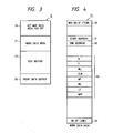
- Fig. 3 shows a data format of the RAM 9 of the word processor of the embodiment shown in Fig. 1.
- the RAM 9 includes a CRT bit map area 20 for storing image data to be displayed on the CRT 13 in the bit map format, a work data area 21, used during a control operation of the CPU 6, for temporarily storing various data, a text buffer 22 for storing document information, table information, and the
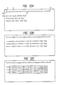
- Figs. 12A to 12C show an input example of document information using decimal tabs.
- Fig. 12A shows input document information, and the same reference numerals in Fig. 12A denote the same parts as in Figs. 8A to 10A.
- Fig. 13 shows the content of the text data area 41 at that time.
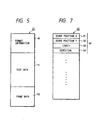
- the start address area 31 designates the start address of document information
- the end address area 32 designates the end address of the document information. Note that in Fig. 13, "-" indicates a tab code, and " ⁇ " indicates a return code.
- Fig. 12B shows a display example determined by selecting tab information corresponding to tab codes set on the basis of the document information shown in Fig. 13.
- "t” indicates a standard tab set position
- "d” indicates a decimal tab set position.
- Fig. 12C shows a frame at that time. This frame data is automatically generated by a process to be described later.
- Fig. 14 shows frame data at that time.
- 140 designates four vertical line data in Fig. 12C
- 141 designates four horizontal line data in Fig. 12C.
- Figs. 15A, 15B, and 15C are views for explaining an automatic changing operation of a right margin upon input of table data.
- a document (numerals) is input up to a right margin position indicated by "R”, and an input operation is made to a position indicated by a cursor 151 in Fig. 15A.
- Fig. 15B shows a case wherein numerals are input in the same line. In this case, the right margin position is moved to the right in correspondence with the input position.
- Fig. 15C shows a case wherein numerals are kept input in the same line. In this case, the right margin is moved to a maximum allowable range (position of "R") of one line. In this manner, when a document is input while exceeding the right margin position, the right margin position is moved in correspondence with an input of the document information.
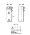
- Figs. 16A to 16C show a data format of the work area 33 (Fig. 4) in the work data area 21.
- Fig. 16A shows a table for holding position information used for determining a tab position.
- This table can store (N-1) pieces of item information per line.
- wP n represents the number of digits of numerals on the left-hand side of a decimal point
- wS n represents the number of digits (including the decimal point) of numerals on the right-hand side of the decimal point.
- the table shown in Fig. 16A is generated when data in table data are checked, and maximum numbers in items are set.
- Fig. 16C shows values determined by the second line in Fig. 9C including maximum items.
- maximum item lengths wT, , wT 2 , and wT 3 are determined, and the lengths of space portions assigned on both sides of these items are indicated by w, to w 3 .
- w n in Fig. 16A corresponds to w 1 to W4 in Fig. 16C.
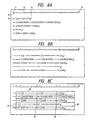
- Figs. 17A to 17D show position information of these data.
- Fig. 17A corresponds to position information of Fig. 8B.
- This position information is set for a line (second line) in which items have maximum numbers of digits. More specifically, the number of digits w, of a left-end space is set to be "5", and the number of characters wP, of the first item is "10". Since this value does not include digits below the decimal point, wT 1 is also set to be “10". Spaces w 2 and w 3 between the first and second items and between the second and third items are set to be "4". The number of digits W4 of a right-end space is set to be "5".
- Fig. 17 B shows position information of Fig. 9B
- Fig. 17C shows position information of Fig. 10B
- Fig. 17D shows position information of Fig. 12B.
- w, 7, wP, represents 8 digits of "clothing”
- wP 2 is "3" on the basis of the number of digits higher than the decimal point of a number "100.00" of the second item
- wS 2 represents 3 digits including the decimal point.
- wT 2 is "6".
- w 2 is obtained as "6" based on a space between the last character position of characters "clothing" having the maximum number of digits in the first item, and the start position of a the number "100.00” having the maximum number of digits in the second item.
- Figs. 18A to 18D show an example of format information shown in detail in Figs. 16A to 16C.
- Fig. 18A shows format information of Fig. 8B.
- the left margin position is set to be "1”
- These decimal tab positions correspond to those in Fig. 12B.
- a column position (F m ) of each frame is given by:
- F m the maximum number of digits
- Figs. 19 to 26 are flow charts showing processes in this English word processor.
- the control programs for executing these control operations are stored in the program ROM 3. The operations of this embodiment will be described below with reference to these flow charts and the drawings mentioned above.
- Fig. 19 shows a text editing process of the word processor of this embodiment. This process is started when document information is input from the KB 1.
- step S2 a key input process of a key code input from the KB 1 is executed.
- step S3 it is checked if the input key is a table making key for starting a table process. If YES in step S3, the flow advances to step S4, and the table input process is executed. If NO in step S3, the flow advances to a corresponding process routine. For example, in step S5, a text input process by character keys is executed.
- the table process as the characteristic feature of this embodiment will be described below.
- Fig. 20 is a flow chart showing the table input process in step S4 in Fig. 19.
- step S10 an input process of a key code input from the KB 1 is executed, and it is checked in step S11 if a table input end key is depressed. If YES in step S11, the flow advances to step S12, and table format information is formed. This process will be described later with reference to Fig. 22 and subsequent drawings.
- step S13 The flow then advances to step S13 to check if a frame making process is instructed. If YES in step S13, the flow advances to step S14, and frame information is formed.
- the frame information making process will be described in detail later with reference to Fig. 26.
- the flow then advances to step S15, and a text display process of a text including table information is executed.
- step S11 If it is determined in step S11 that the table input end key is not depressed, the flow advances to step S17 to check if an editing key is depressed. If YES in step S17, the flow advances to step S18, and a table making & editing process is executed. Thereafter, the flow advances to the text display process in step S23. If NO in step S17, however, the flow advances to step S19 to check if an input character code is on the right margin position. If YES in step S19, the flow advances to step S20 to execute a right margin release process. In step S22, a cursor movement process upon input of a function key or a character key is executed. The flow then advances to step S23, and a text display process is executed. Of steps S17 to S23, process routines excluding step S20 are known to those who are skilled in the art, and a description thereof will not be particularly made here.
- Fig. 21 is a flow chart showing the right margin release process in step S20 in Fig. 20.
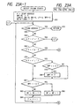
- step S30 It is checked in step S30 if the right margin position is a maximum (right end) position. If YES in step S30, since the right margin position can no longer be moved to the right, the flow returns to the main maximum column count) is set in WT CLM in correspondence with each item.
- step S41 Fig. 22
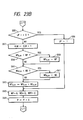
- a space amount (w n ) corresponding to each item is computed. This process will be described below with reference to the flow chart of Fig. 24.
- step S90 the number of columns between the right and left margin positions is computed, and a character portion is subtracted from the computed value, thus computing a total of space amounts in one line. This equation is given by: where m is the maximum item count.
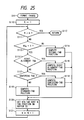
- Fig. 25 is a flow chart showing the format change process in step S44 shown in Fig. 22.
- step S117 If it is determined in step S117 that centering tabs are to be set, the flow advances to step S118, and centering tab positions are computed on the basis of the above-mentioned equation. However, if NO in step S117, the flow advances to step S119, and standard tab positions are computed on the basis of the above-mentioned equation. Note that as w n , wT n , and wP n used in these equations, the values computed in step S40 are used.
- step S120 a sort of tab and a tab position corresponding to an Nth item are set in the format information area 40 (Fig. 6) of the text buffer 22.
- step S121 increment N by one, and the flow then returns to step S111.
- Fig. 26 is a flow chart showing the frame information making process in step S14 of Fig. 20.
- step S130 the pointer N is set to be "1". If it is determined in step S131 that N is smaller than (m + 1: m is the maximum item count), the flow advances to step S139, a y-position is set to be "1" (first line). The flow then advances to step S140, and the horizontal column position is computed by the above-mentioned equation (F(w n-1 + wT n .,) + w r /2) for computing a horizontal position of a frame. The flow then advances to step S141, and the number of lines is set in a vertical length. In step S142, vertical line data is set. Thus, for example, data of the vertical line 77 shown in Fig. 8C is obtained, and frame data designated by reference numeral 140a in Fig. 14 is stored. The flow then advances to step S143 to increment N by one, and the flow returns to step S131.
- step S132 the pointer N is set to be "1".
- step S132a the y-position is set to indicate the first line.
- step S138 horizontal line data is set.
- step S138a increment N by one, and the flow advances to step S134.
- horizontal table data is formed, as designated by reference numeral 141 in Fig. 14.
Landscapes
- Engineering & Computer Science (AREA)
- Theoretical Computer Science (AREA)
- Health & Medical Sciences (AREA)
- Artificial Intelligence (AREA)
- Audiology, Speech & Language Pathology (AREA)
- Computational Linguistics (AREA)
- General Health & Medical Sciences (AREA)
- Physics & Mathematics (AREA)
- General Engineering & Computer Science (AREA)
- General Physics & Mathematics (AREA)
- Document Processing Apparatus (AREA)
- Character Input (AREA)
Applications Claiming Priority (2)
| Application Number | Priority Date | Filing Date | Title |
|---|---|---|---|
| JP90848/89 | 1989-04-12 | ||
| JP01090848A JP3105895B2 (ja) | 1989-04-12 | 1989-04-12 | 文書処理装置 |
Publications (3)
| Publication Number | Publication Date |
|---|---|
| EP0392825A2 true EP0392825A2 (de) | 1990-10-17 |
| EP0392825A3 EP0392825A3 (de) | 1992-09-02 |
| EP0392825B1 EP0392825B1 (de) | 1997-08-27 |
Family
ID=14010003
Family Applications (1)
| Application Number | Title | Priority Date | Filing Date |
|---|---|---|---|
| EP90303918A Expired - Lifetime EP0392825B1 (de) | 1989-04-12 | 1990-04-11 | Dokumentenverarbeitungsapparat |
Country Status (4)
| Country | Link |
|---|---|
| US (1) | US5299303A (de) |
| EP (1) | EP0392825B1 (de) |
| JP (1) | JP3105895B2 (de) |
| DE (1) | DE69031320D1 (de) |
Cited By (1)
| Publication number | Priority date | Publication date | Assignee | Title |
|---|---|---|---|---|
| EP0574657A3 (de) * | 1992-03-11 | 1994-03-23 | Chinon Ind Inc |
Families Citing this family (11)
| Publication number | Priority date | Publication date | Assignee | Title |
|---|---|---|---|---|
| JP2641318B2 (ja) * | 1990-08-14 | 1997-08-13 | キヤノン株式会社 | 文書処理装置 |
| US5271065A (en) * | 1990-09-28 | 1993-12-14 | Xerox Corporation | Electronic printing system for printing signatures |
| JP3303926B2 (ja) * | 1991-09-27 | 2002-07-22 | 富士ゼロックス株式会社 | 構造化文書分類装置及び方法 |
| JPH06274484A (ja) * | 1993-03-24 | 1994-09-30 | Nec Corp | ワープロによる表作成方法 |
| US6208744B1 (en) * | 1994-12-14 | 2001-03-27 | Casio Computer Co., Ltd. | Document image processor and method for setting a document format conforming to a document image |
| JPH08212203A (ja) * | 1995-02-06 | 1996-08-20 | Fujitsu Ltd | 文書表示装置及び方法 |
| US5895478A (en) * | 1996-08-08 | 1999-04-20 | U S West, Inc. | Right and center font justification for a document system library |
| US6731309B1 (en) | 1998-08-28 | 2004-05-04 | Corel Corporation | Real time preview |
| US7236979B2 (en) * | 2002-06-26 | 2007-06-26 | Microsoft Corporation | Menu-less system and method for interactively manipulating and reformatting data entered in a tabular format in a data processing application |
| JP4332461B2 (ja) * | 2004-04-16 | 2009-09-16 | キヤノン株式会社 | 画像処理装置および方法 |
| US8650482B2 (en) * | 2005-12-14 | 2014-02-11 | Microsoft Corporation | Dynamic positioning and aligning tabs relative to margins indent and column width |
Family Cites Families (14)
| Publication number | Priority date | Publication date | Assignee | Title |
|---|---|---|---|---|
| JPS541535B2 (de) * | 1974-10-23 | 1979-01-25 | ||
| EP0066045A3 (en) * | 1981-05-18 | 1983-07-13 | International Business Machines Corporation | Method for automatically expanding the displayed width of a selected field in a text processing system |
| US4481603A (en) * | 1981-05-18 | 1984-11-06 | International Business Machines Corporation | File processing method using expanding display windows for selected records and text fields |
| US4484826A (en) * | 1981-09-24 | 1984-11-27 | International Business Machines Corporation | Automatic intertext column spacing |
| JPS58132851A (ja) * | 1982-01-30 | 1983-08-08 | Canon Inc | 文字処理装置 |
| JPS60127184A (ja) * | 1983-12-14 | 1985-07-06 | Canon Inc | 記録装置 |
| US5055998A (en) * | 1984-12-10 | 1991-10-08 | Wang Laboratories, Inc. | Intermediate spreadsheet structure |
| US4977536A (en) * | 1984-12-10 | 1990-12-11 | Canon Kabushiki Kaisha | Document processor |
| GB2170335B (en) * | 1984-12-29 | 1989-07-26 | Canon Kk | Information processing apparatus |
| JPS61158389A (ja) * | 1984-12-29 | 1986-07-18 | キヤノン株式会社 | 罫線処理装置 |
| US4783760A (en) * | 1985-06-03 | 1988-11-08 | Honeywell Bull Inc. | Word processing text justification method |
| JPS63266574A (ja) * | 1987-04-24 | 1988-11-02 | Hitachi Ltd | 文書作成装置 |
| EP0298166B1 (de) * | 1987-07-08 | 1992-09-23 | International Business Machines Corporation | Datenverarbeitungsanlage zur automatischen Veränderung von Datenformaten |
| US4951233A (en) * | 1987-08-05 | 1990-08-21 | Hitachi, Ltd. | Document producing apparatus having in-document layout display |
-
1989
- 1989-04-12 JP JP01090848A patent/JP3105895B2/ja not_active Expired - Fee Related
-
1990
- 1990-04-11 DE DE69031320T patent/DE69031320D1/de not_active Expired - Lifetime
- 1990-04-11 EP EP90303918A patent/EP0392825B1/de not_active Expired - Lifetime
-
1993
- 1993-08-20 US US08/109,459 patent/US5299303A/en not_active Expired - Lifetime
Cited By (3)
| Publication number | Priority date | Publication date | Assignee | Title |
|---|---|---|---|---|
| EP0574657A3 (de) * | 1992-03-11 | 1994-03-23 | Chinon Ind Inc | |
| US5448685A (en) * | 1992-03-11 | 1995-09-05 | Chinon Industries, Inc. | Label printing apparatus and wordprocessor |
| US5559934A (en) * | 1992-03-11 | 1996-09-24 | Chinon Industries, Inc. | Label printing apparatus and wordprocessor |
Also Published As
| Publication number | Publication date |
|---|---|
| EP0392825B1 (de) | 1997-08-27 |
| JP3105895B2 (ja) | 2000-11-06 |
| JPH02291055A (ja) | 1990-11-30 |
| EP0392825A3 (de) | 1992-09-02 |
| US5299303A (en) | 1994-03-29 |
| DE69031320D1 (de) | 1997-10-02 |
Similar Documents
| Publication | Publication Date | Title |
|---|---|---|
| US5717794A (en) | Document recognition method and system | |
| US7191390B2 (en) | Automated paragraph layout | |
| KR930009761B1 (ko) | 워드프로세서 | |
| EP0394633A2 (de) | Von der Sprache unabhängiges Verfahren zur Isolierung von Wörtern eines Textes unter Verwendung von in Kategorien klassifizierten Zeichen | |
| EP0139344B1 (de) | Verfahren und Einrichtung zum automatischen Erhalten von Zeichenzwischenräumen während der Satzaufbereitung | |
| US4677585A (en) | Method for obtaining common mode information and common field attribute information for a plurality of card images | |
| EP0392825B1 (de) | Dokumentenverarbeitungsapparat | |
| EP0258069B1 (de) | Informationsprozessor zur Prüfung von Daten | |
| JPH06124078A (ja) | 欧文文書処理に於けるカーニング処理方法 | |
| JPH0634256B2 (ja) | 接触文字切出し方法 | |
| US6504540B1 (en) | Method and apparatus for altering one or more attributes of one or more blocks of image data in a document | |
| EP0519713B1 (de) | Verfahren und Gerät zur Zeicheneingabe | |
| JPS61214051A (ja) | 電子辞書 | |
| JP2915175B2 (ja) | 単語間スペース検出方法 | |
| JPH04290184A (ja) | 手書き文書作成装置 | |
| JP3128357B2 (ja) | 文字認識処理装置 | |
| JPH0935006A (ja) | 文字認識装置 | |
| EP0335644A2 (de) | Textverarbeitungsgerät | |
| JPH03177963A (ja) | 漢字分類方法及び漢字分類表及び漢字処理装置 | |
| JP3157530B2 (ja) | 文字切り出し方法 | |
| JP3338570B2 (ja) | 自然言語の一括処理における処理終了時間の予測装置 | |
| JPS62249269A (ja) | 文書処理装置 | |
| JP2562765B2 (ja) | ワ−ドプロセッサの印字制御方法 | |
| JP3022790B2 (ja) | 手書き文字入力装置 | |
| JPH07296100A (ja) | イメージデータ認識装置 |
Legal Events
| Date | Code | Title | Description |
|---|---|---|---|
| PUAI | Public reference made under article 153(3) epc to a published international application that has entered the european phase |
Free format text: ORIGINAL CODE: 0009012 |
|
| AK | Designated contracting states |
Kind code of ref document: A2 Designated state(s): DE FR GB IT |
|
| 17P | Request for examination filed |
Effective date: 19901231 |
|
| PUAL | Search report despatched |
Free format text: ORIGINAL CODE: 0009013 |
|
| AK | Designated contracting states |
Kind code of ref document: A3 Designated state(s): DE FR GB IT |
|
| 17Q | First examination report despatched |
Effective date: 19940817 |
|
| GRAG | Despatch of communication of intention to grant |
Free format text: ORIGINAL CODE: EPIDOS AGRA |
|
| GRAH | Despatch of communication of intention to grant a patent |
Free format text: ORIGINAL CODE: EPIDOS IGRA |
|
| GRAH | Despatch of communication of intention to grant a patent |
Free format text: ORIGINAL CODE: EPIDOS IGRA |
|
| GRAA | (expected) grant |
Free format text: ORIGINAL CODE: 0009210 |
|
| AK | Designated contracting states |
Kind code of ref document: B1 Designated state(s): DE FR GB IT |
|
| REF | Corresponds to: |
Ref document number: 69031320 Country of ref document: DE Date of ref document: 19971002 |
|
| ET | Fr: translation filed | ||
| ITF | It: translation for a ep patent filed | ||
| PG25 | Lapsed in a contracting state [announced via postgrant information from national office to epo] |
Ref country code: DE Effective date: 19971128 |
|
| PG25 | Lapsed in a contracting state [announced via postgrant information from national office to epo] |
Ref country code: GB Free format text: LAPSE BECAUSE OF NON-PAYMENT OF DUE FEES Effective date: 19980411 |
|
| PLBE | No opposition filed within time limit |
Free format text: ORIGINAL CODE: 0009261 |
|
| STAA | Information on the status of an ep patent application or granted ep patent |
Free format text: STATUS: NO OPPOSITION FILED WITHIN TIME LIMIT |
|
| 26N | No opposition filed | ||
| GBPC | Gb: european patent ceased through non-payment of renewal fee |
Effective date: 19980411 |
|
| PGFP | Annual fee paid to national office [announced via postgrant information from national office to epo] |
Ref country code: IT Payment date: 20080422 Year of fee payment: 19 |
|
| PGFP | Annual fee paid to national office [announced via postgrant information from national office to epo] |
Ref country code: FR Payment date: 20080331 Year of fee payment: 19 |
|
| REG | Reference to a national code |
Ref country code: FR Ref legal event code: ST Effective date: 20091231 |
|
| PG25 | Lapsed in a contracting state [announced via postgrant information from national office to epo] |
Ref country code: FR Free format text: LAPSE BECAUSE OF NON-PAYMENT OF DUE FEES Effective date: 20091222 |
|
| PG25 | Lapsed in a contracting state [announced via postgrant information from national office to epo] |
Ref country code: IT Free format text: LAPSE BECAUSE OF NON-PAYMENT OF DUE FEES Effective date: 20090411 |