EP0392961A1 - Nahtspurführung zwischen zusammengepassten Teilen - Google Patents
Nahtspurführung zwischen zusammengepassten Teilen Download PDFInfo
- Publication number
- EP0392961A1 EP0392961A1 EP90630061A EP90630061A EP0392961A1 EP 0392961 A1 EP0392961 A1 EP 0392961A1 EP 90630061 A EP90630061 A EP 90630061A EP 90630061 A EP90630061 A EP 90630061A EP 0392961 A1 EP0392961 A1 EP 0392961A1
- Authority
- EP
- European Patent Office
- Prior art keywords
- seam
- location
- image
- tentative
- width
- Prior art date
- Legal status (The legal status is an assumption and is not a legal conclusion. Google has not performed a legal analysis and makes no representation as to the accuracy of the status listed.)
- Granted
Links
Images

Classifications
-
- G—PHYSICS
- G01—MEASURING; TESTING
- G01C—MEASURING DISTANCES, LEVELS OR BEARINGS; SURVEYING; NAVIGATION; GYROSCOPIC INSTRUMENTS; PHOTOGRAMMETRY OR VIDEOGRAMMETRY
- G01C1/00—Measuring angles
- G01C1/02—Theodolites
- G01C1/04—Theodolites combined with cameras
-
- B—PERFORMING OPERATIONS; TRANSPORTING
- B25—HAND TOOLS; PORTABLE POWER-DRIVEN TOOLS; MANIPULATORS
- B25J—MANIPULATORS; CHAMBERS PROVIDED WITH MANIPULATION DEVICES
- B25J9/00—Program-controlled manipulators
- B25J9/16—Program controls
- B25J9/1694—Program controls characterised by use of sensors other than normal servo-feedback from position, speed or acceleration sensors, perception control, multi-sensor controlled systems, sensor fusion
- B25J9/1697—Vision controlled systems
-
- G—PHYSICS
- G05—CONTROLLING; REGULATING
- G05B—CONTROL OR REGULATING SYSTEMS IN GENERAL; FUNCTIONAL ELEMENTS OF SUCH SYSTEMS; MONITORING OR TESTING ARRANGEMENTS FOR SUCH SYSTEMS OR ELEMENTS
- G05B19/00—Program-control systems
- G05B19/02—Program-control systems electric
- G05B19/42—Recording and playback systems, i.e. in which the program is recorded from a cycle of operations, e.g. the cycle of operations being manually controlled, after which this record is played back on the same machine
- G05B19/425—Teaching successive positions by numerical control, i.e. commands being entered to control the positioning servo of the tool head or end effector
-
- G—PHYSICS
- G05—CONTROLLING; REGULATING
- G05B—CONTROL OR REGULATING SYSTEMS IN GENERAL; FUNCTIONAL ELEMENTS OF SUCH SYSTEMS; MONITORING OR TESTING ARRANGEMENTS FOR SUCH SYSTEMS OR ELEMENTS
- G05B2219/00—Program-control systems
- G05B2219/30—Nc systems
- G05B2219/36—Nc in input of data, input key till input tape
- G05B2219/36417—Programmed coarse position, fine position by alignment, follow line, path adaptive
Definitions
- the invention relates to tracking of a seam in material to be joined; and in particular, to refining a coarsely taught trajectory.
- the seam to be followed is rough taught to the robot.
- This rough tentative trajectory is refined with the parts to be joined in place.
- a matrix camera is focused on the seam establishing electronic image which includes the seam.
- the image is rotated so that the horizontal direction of the electronic image sweep is perpendicular to the tentative direction of the track.
- This rotated image is then evaluated to locate the edges of the seam based on the local gray level gradients.
- the offset of this actual location from the tentative track is remembered by the processor and applied during the later welding operation.
- False readings of the seam location are deterred by processing the data in a manner to emphasize the edges of the seam.
- a filter is applied using negative coefficients on one side of the point under inspection and a positive amplification on the other side to produce high negative and positive peaks in the resulting data.
- This filter is equal to or a little less than twice the width of the seam so that it will react most strongly to an indication approximating the seam width and thereby give lower indications for scratches and other false readings.
- Other criteria is also applied to differentiate between the proper seam location indication and other aberrations. These include comparing the distance between peaks to the expected width of the seam either from knowledge of the design or from storage of a previous frame. Proper left to right orientation of maximum and minimum values avoids the need to investigate erroneous readings. The system may furthermore react more favorably to maximum peaks in either the positive or negative direction. Each of the various criteria may be weighted for voting with these criteria then applied to the process signal to select that which gives the actual seam location.
- a robot 10 carries a weld head 12 used ultimately to weld a seam 14 between work pieces 16 and 18. Also located on the robot is video camera 20 with lens 22 and illumination source 24. The camera and weld head are not used simultaneously and each is arranged to be out of the way of the other during operation. Of course, the camera is in location during the refinement of the track, the offset between the weld torch and the camera is known and compensated for within the robot.
- Fig. 2 illustrates a seam 14 to be tracked between work pieces 16 and 18.
- a tentative track 26 may be established by earlier calculation but is preferably established by the use of a conventional teach pendant.
- the teach pendant is placed at locations 27 through 31 sequentially so that the robot is programmed to establish a straight line path between these points.
- Fig. 3 illustrates a plurality of smaller discrete steps which are taken in refining the coarsely taught tentative trajectory in accordance with the invention.
- Fig. 4 illustrates this in more detail.
- the centerline of the seam 34 lies between the left edge 36 of the seam and the right edge 38 of the seam.
- View lines 40 crossing the seam are perpendicular to the tentative track 26 and accordingly may not be precisely perpendicular to the seam although they are close to that position.
- the camera 20 is focused on the work piece at an initial location on the tentative track which includes the seam.
- An electronic image is formed, and while it need not necessarily be transferred to a video image, the video image is shown for purposes of description.
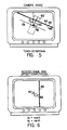
- the image seen may be as shown in Fig. 5.
- Point 42 is the center point which is located on the tentative track location.
- Line 44 represents the image of the seam with a left edge 46 and a right edge 48.
- a wide rectangle 50 is selected with its center being the base location 42, and with the rectangle in its long dimension being perpendicular to tentative track 26.
- the image may be electronically rotated to the rotated form illustrated in Fig. 6.
- the offset 52 of the actual seam location with respect to the nominal point 42 on the tentative tracking line is a dimension to be determined. With the image electronically rotated, this can be relatively simply accomplished by examining pixels in the horizontal electronic scan of the rotated image. It is an object of this invention to locate the seam with respect to the initial location 42 for correction of the tentative track. It is also important that differentiation be made between the actual seam and other scratches and defects on the material.
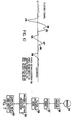
- Fig. 7 illustrates the steps in the overall logic in achieving this results.
- 54 indicates establishment of an electronic image with box 56 illustrating the rotation of the window to the horizontal position in the electronic image.
- each vertical column including a selected plurality of rows is averaged with the result treated as a single horizontal scan.
- This averaging process improves the signal to noise ratio by reducing or eliminating the effects of noise spots and scratches or lighting artifacts which do not run approximately parallel to the seam.
- a trade-off between the number of rows in the window and a seam location accuracy must also be considered if the seam has significant curvature to it or if the seam deviates significantly from vertical.
- the resulting row of data is processed with a filter to enhance the edges of the seam.
- a majority voting feature processor 59 applies weight values to various features to facilitate location of the seam and to reject spurious signals. As indicated in box 60, the new seam position and width may then be calculated with this information being retained in memory and applied as an offset to the tentative track. For a later welding operation, the tentative track with a known offset provides precise positioning for welding or any other operation carried out.
- the invention may be used one of two ways. Where fixturing is precise and tolerance of the various pieces is closely held, the roughly taught path may be corrected only once with the corrected path being used for welding of all the pieces. Alternatively, the same coarsely taught tentative path, or a previously refined path, may be used with the refinement operation carried out for each new welding operation, this being practical because of the speed and simplicity of the operation.
- step 58 which filters the averaged row of pixels
- curve 62 represents the gray level electronically determined in a horizontal scan with a decrease in the gray level at scratch 64 and seam 66.
- the averaged row of data referred to as the raw data is then processed with the filter to enhance the edges of the seam.
- the filtering process is performed by convolving the row of image data with a coefficient factor representing the filter.
- convolution is defined as a weight sum of the gray level values in a one pixel by two K pixel neighborhood.
- J is the pixel under investigation, and U represents the adjacent pixels from minus K to plus K
- the processing value at J equals the summation from minus K to plus K, of the filter applied coefficient at each location times the gray level at each location. This is represented as
- the coefficients of the filter are chosen so that the resulting signal peaks where the edges (gradients) occur. For instance, the coefficient is minus 1 for all minus K positions and plus 1 for all plus K positions.
- the left edge of a seam is indicated by a negative peak 68 since the high intensity pixels on the left side of the edge would be subtracted from the low intensity pixels on the right side of the edge.
- the right edge of the seam is indicated by a positive peak 70 in the filtered signal.
- the parameter K is selected to be less than or equal to the smallest expected width of the seam in pixels.
- a fixed value of K based on the known seam width may be used if desired. However, an improvement under some conditions may be achieved by storing the last frame of data and determining the width of the seam in this earlier frame. The width of this seam from the earlier frame is then used to establish the K for the subsequent frame.
- the next step is to process the filtered signal to locate the edges of the seam and the majority voting feature process of 59 facilitates this.
- the edges of the seam are indicated by negative and positive peaks, there may be other more intense peaks caused by scratches in the surface of the part, lighting artifacts, and other types of noise.
- the location (J) and the corresponding process values of the edge peaks are sent to the majority voting feature processor.
- the positive peaks 76 and the negative peaks 78 are sent to the voting feature processor 59. All valid negative peak and positive peak combinations are determined from logical thresholds and comparisons. For example, peaks may be eliminated from consideration immediately if their values did not exceed a specified threshold. Scanning the signal from left to right combinations which have a positive peak occurring before a negative peak are eliminated immediately. The width of a combination is computed by subtracting the location of the negative peak from the location of the positive peak. If the width does not fall within a specified range, that combination is eliminated.
- the resulting candidate combinations are then awarded weighted votes based on certain features. For example, one vote may be assigned to any combination which includes the most negative peak or the most positive peak. A vote may be awarded to the combination with the highest edge strength, where edge strength is computed by subtracting the negative peak value from the positive peak value. The center gray level intensity between edges may be computed for each combination from the raw image data and a vote awarded to the lowest intensity.
- the seam location is computed as the average position between the negative and positive peaks, this representing the centerline of the seam.
- This width determination may be sent through line 80 to frame delay 82, and the width from the previous frame used to award a weighted vote based on how close the width between two peaks is to the width of the seam as determined by the previous votes.
- a weighted vote may be based on the proximity of the peak indications to the location of the seam in the previous frame.
- the features and weights used in the majority voting schemes are application dependent. For example, if the light source is uniform and the surface is fairly clean, the center gray level intensity of the combination may be given more weight. For an application where lighting cannot be controlled, the gray level intensity may be given no weight.
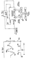
- An example of a majority voting process is shown in Fig. 10. In this case, the features given weights are the lowest and highest peaks, the nearest width to the previous seam width, and the nearest location to the previous seam location. All votes having a weighting value of 1.
- the filtered signal 86 has negative peaks at pixel locations 29, 55 and 84 with positive peaks at pixel locations 39, 45 and 67.
- Table 1 shows the various combinations of peaks and the location representing the center between the two pixel locations.
- the first two combinations in the table are potentially valid.
- the 29, 67 combination shows a width of 38 pixels which is out of range.
- the 55, 39 combination is invalid because of the reversed left to right orientation of the peaks, this also applying to several other combinations.
- the 55, 67 combination is potentially valid.
- Table 2 shows the majority voting applied to the three potentially valid combinations.
- the combination 29, 45 while not having the highest positive peak, has the lowest negative peak, a width closest to the previous seam width and the nearest location to the previous seam location. It accordingly has the majority of votes awarded thereto.
Landscapes
- Engineering & Computer Science (AREA)
- Robotics (AREA)
- Physics & Mathematics (AREA)
- General Physics & Mathematics (AREA)
- Automation & Control Theory (AREA)
- Mechanical Engineering (AREA)
- Radar, Positioning & Navigation (AREA)
- Remote Sensing (AREA)
- Length Measuring Devices By Optical Means (AREA)
- Image Processing (AREA)
- Image Analysis (AREA)
- Manipulator (AREA)
Applications Claiming Priority (2)
| Application Number | Priority Date | Filing Date | Title |
|---|---|---|---|
| US07/325,427 US4922174A (en) | 1989-03-20 | 1989-03-20 | Seam tracking between mating parts |
| US325427 | 1989-03-20 |
Publications (2)
| Publication Number | Publication Date |
|---|---|
| EP0392961A1 true EP0392961A1 (de) | 1990-10-17 |
| EP0392961B1 EP0392961B1 (de) | 1994-04-27 |
Family
ID=23267840
Family Applications (1)
| Application Number | Title | Priority Date | Filing Date |
|---|---|---|---|
| EP90630061A Expired - Lifetime EP0392961B1 (de) | 1989-03-20 | 1990-03-05 | Nahtspurführung zwischen zusammengepassten Teilen |
Country Status (5)
| Country | Link |
|---|---|
| US (1) | US4922174A (de) |
| EP (1) | EP0392961B1 (de) |
| JP (1) | JPH02285204A (de) |
| KR (1) | KR900014859A (de) |
| DE (1) | DE69008409T2 (de) |
Cited By (1)
| Publication number | Priority date | Publication date | Assignee | Title |
|---|---|---|---|---|
| WO2002070211A1 (de) * | 2001-03-08 | 2002-09-12 | Carl Zeiss | Koordinatenmessgerät mit einem videotastkopf |
Families Citing this family (10)
| Publication number | Priority date | Publication date | Assignee | Title |
|---|---|---|---|---|
| US5270516A (en) * | 1991-04-01 | 1993-12-14 | Matsushita Electric Industrial Co., Ltd. | Arc welding machine |
| JP2768053B2 (ja) * | 1991-05-16 | 1998-06-25 | 住友金属工業株式会社 | 電縫鋼管のシーム部位置検出装置 |
| GB9707954D0 (en) * | 1997-04-19 | 1997-06-11 | Integrated Sensor Systems Limi | An improved remote operator viewing system for arc welding |
| PT1448334E (pt) * | 2001-11-15 | 2011-06-28 | Precitec Vision Gmbh & Co Kg | Processo e dispositivo para detetar a qualidade de uma costura de soldadura durante a soldadura de peças de trabalho |
| DE102004033710B4 (de) * | 2004-07-13 | 2010-02-11 | Gutsch & Exner Software Gmbh | Verfahren zum Verbinden eines Hauptträgers mit mindestens einem Anbauteil durch Schweißen |
| DE102004036127A1 (de) * | 2004-07-24 | 2006-02-16 | Gutsch & Exner Software Gmbh | Verfahren und Maschine zum Verbinden eines Hauptträgers mit mindestens einem zuvor nicht in der benötigten Position befindlichen Anbauteil durch Schweißen |
| CN101623867B (zh) * | 2008-07-11 | 2010-12-01 | 中国科学院沈阳自动化研究所 | 一种使机器人高精度跟踪指定路径的设备和方法 |
| JP5920401B2 (ja) * | 2013-05-21 | 2016-05-18 | Jfeスチール株式会社 | 電縫管の超音波探傷装置及び方法ならびに品質保証方法 |
| JP6339651B1 (ja) * | 2016-12-02 | 2018-06-06 | ファナック株式会社 | アーク溶接ロボットシステム |
| US20230211437A1 (en) * | 2020-07-15 | 2023-07-06 | Fanuc Corporation | Laser machining system |
Citations (3)
| Publication number | Priority date | Publication date | Assignee | Title |
|---|---|---|---|---|
| EP0113010A1 (de) * | 1982-11-30 | 1984-07-11 | Siemens Aktiengesellschaft | Robotersteuerung |
| AT375855B (de) * | 1979-10-05 | 1984-09-25 | Schuler Albert Dipl Ing Dr Tec | Vorrichtung zur positionierung einer schweisseinrichtung entlang beliebiger, ebener schweissfugen |
| US4595820A (en) * | 1982-10-22 | 1986-06-17 | The Ohio State University | Apparatus and methods for controlling a welding process |
Family Cites Families (4)
| Publication number | Priority date | Publication date | Assignee | Title |
|---|---|---|---|---|
| US4593173A (en) * | 1982-11-08 | 1986-06-03 | National Research Development Corp. | Electronic apparatus for automatic control of the placing of material at a junction between surfaces |
| US4542279A (en) * | 1983-03-07 | 1985-09-17 | General Electric Company | Microvector control for edge and joint following |
| US4568816A (en) * | 1983-04-19 | 1986-02-04 | Unimation, Inc. | Method and apparatus for manipulator welding apparatus with improved weld path definition |
| US4737614A (en) * | 1986-04-22 | 1988-04-12 | The Ohio State University Research Foundation | Optical image control for automated arc welding system vision system |
-
1989
- 1989-03-20 US US07/325,427 patent/US4922174A/en not_active Expired - Fee Related
-
1990
- 1990-03-05 DE DE69008409T patent/DE69008409T2/de not_active Expired - Fee Related
- 1990-03-05 EP EP90630061A patent/EP0392961B1/de not_active Expired - Lifetime
- 1990-03-17 KR KR1019900003572A patent/KR900014859A/ko not_active Withdrawn
- 1990-03-20 JP JP2071721A patent/JPH02285204A/ja active Pending
Patent Citations (3)
| Publication number | Priority date | Publication date | Assignee | Title |
|---|---|---|---|---|
| AT375855B (de) * | 1979-10-05 | 1984-09-25 | Schuler Albert Dipl Ing Dr Tec | Vorrichtung zur positionierung einer schweisseinrichtung entlang beliebiger, ebener schweissfugen |
| US4595820A (en) * | 1982-10-22 | 1986-06-17 | The Ohio State University | Apparatus and methods for controlling a welding process |
| EP0113010A1 (de) * | 1982-11-30 | 1984-07-11 | Siemens Aktiengesellschaft | Robotersteuerung |
Non-Patent Citations (1)
| Title |
|---|
| WELDING JOURNAL * |
Cited By (1)
| Publication number | Priority date | Publication date | Assignee | Title |
|---|---|---|---|---|
| WO2002070211A1 (de) * | 2001-03-08 | 2002-09-12 | Carl Zeiss | Koordinatenmessgerät mit einem videotastkopf |
Also Published As
| Publication number | Publication date |
|---|---|
| DE69008409D1 (de) | 1994-06-01 |
| EP0392961B1 (de) | 1994-04-27 |
| US4922174A (en) | 1990-05-01 |
| KR900014859A (ko) | 1990-10-25 |
| JPH02285204A (ja) | 1990-11-22 |
| DE69008409T2 (de) | 1994-08-11 |
Similar Documents
| Publication | Publication Date | Title |
|---|---|---|
| EP0532257B1 (de) | Apparat zum Bestimmen der Schweissnahtgüte | |
| US5771309A (en) | Method for measuring position of hole | |
| US4922174A (en) | Seam tracking between mating parts | |
| Li et al. | Narrow weld joint recognition method based on laser profile sensor | |
| KR100415796B1 (ko) | 스캐닝간격결정방법 | |
| JP3160838B2 (ja) | 表面欠陥検査装置 | |
| JP3758763B2 (ja) | 孔位置の光学的計測方法 | |
| JP3151790B2 (ja) | 溶接開先・ビードの中心位置検出方法及び装置 | |
| JP2003311464A (ja) | 環形状溶接部の溶接状態検査装置および検査方法 | |
| JP2912070B2 (ja) | 対象物の位置認識方法 | |
| JPH0656363B2 (ja) | 表面欠陥検査装置のデ−タ出力方法 | |
| JPH03118975A (ja) | 溶接装置 | |
| JP3303649B2 (ja) | 物体の形状欠損の検出方法及び検出装置 | |
| CN120506911B (zh) | 一种后视镜平整度检测方法及系统 | |
| JPH05203584A (ja) | ワーク表面特徴量検出装置 | |
| JPH09259320A (ja) | 円形物体の位置決定方法 | |
| JPH08103871A (ja) | 自動溶接方法 | |
| JPH08114425A (ja) | 光学式圧延板形状検出方法 | |
| JPH10202478A (ja) | スローアウェイチップの検査方法および検査装置 | |
| JP2000121333A (ja) | 外観検査装置及び外観検査方法 | |
| JP3102983B2 (ja) | 開先位置検出方法 | |
| JPH08304026A (ja) | エリアセンサを使用してなる溶接方法 | |
| Falkowski et al. | Vision sensing for arc welding robots-a new approach | |
| JPS62127603A (ja) | 相対位置計測修正方法と装置 | |
| JP2974788B2 (ja) | パターン位置検出方法 |
Legal Events
| Date | Code | Title | Description |
|---|---|---|---|
| PUAI | Public reference made under article 153(3) epc to a published international application that has entered the european phase |
Free format text: ORIGINAL CODE: 0009012 |
|
| AK | Designated contracting states |
Kind code of ref document: A1 Designated state(s): DE ES FR GB IT SE |
|
| 17P | Request for examination filed |
Effective date: 19901218 |
|
| 17Q | First examination report despatched |
Effective date: 19920707 |
|
| GRAA | (expected) grant |
Free format text: ORIGINAL CODE: 0009210 |
|
| AK | Designated contracting states |
Kind code of ref document: B1 Designated state(s): DE ES FR GB IT SE |
|
| PG25 | Lapsed in a contracting state [announced via postgrant information from national office to epo] |
Ref country code: IT Free format text: LAPSE BECAUSE OF FAILURE TO SUBMIT A TRANSLATION OF THE DESCRIPTION OR TO PAY THE FEE WITHIN THE PRE;WARNING: LAPSES OF ITALIAN PATENTS WITH EFFECTIVE DATE BEFORE 2007 MAY HAVE OCCURRED AT ANY TIME BEFORE 2007. THE CORRECT EFFECTIVE DATE MAY BE DIFFERENT FROM THE ONE RECORDED.SCRIBED TIME-LIMIT Effective date: 19940427 Ref country code: FR Effective date: 19940427 Ref country code: ES Free format text: THE PATENT HAS BEEN ANNULLED BY A DECISION OF A NATIONAL AUTHORITY Effective date: 19940427 Ref country code: SE Free format text: THE PATENT HAS BEEN ANNULLED BY A DECISION OF A NATIONAL AUTHORITY Effective date: 19940427 |
|
| REF | Corresponds to: |
Ref document number: 69008409 Country of ref document: DE Date of ref document: 19940601 |
|
| EN | Fr: translation not filed | ||
| PLBE | No opposition filed within time limit |
Free format text: ORIGINAL CODE: 0009261 |
|
| STAA | Information on the status of an ep patent application or granted ep patent |
Free format text: STATUS: NO OPPOSITION FILED WITHIN TIME LIMIT |
|
| PG25 | Lapsed in a contracting state [announced via postgrant information from national office to epo] |
Ref country code: GB Effective date: 19950305 |
|
| 26N | No opposition filed | ||
| GBPC | Gb: european patent ceased through non-payment of renewal fee |
Effective date: 19950305 |
|
| PGFP | Annual fee paid to national office [announced via postgrant information from national office to epo] |
Ref country code: DE Payment date: 19970224 Year of fee payment: 8 |
|
| PG25 | Lapsed in a contracting state [announced via postgrant information from national office to epo] |
Ref country code: DE Free format text: LAPSE BECAUSE OF NON-PAYMENT OF DUE FEES Effective date: 19981201 |