EP0396762A1 - Machine a coudre - Google Patents
Machine a coudre Download PDFInfo
- Publication number
- EP0396762A1 EP0396762A1 EP89909900A EP89909900A EP0396762A1 EP 0396762 A1 EP0396762 A1 EP 0396762A1 EP 89909900 A EP89909900 A EP 89909900A EP 89909900 A EP89909900 A EP 89909900A EP 0396762 A1 EP0396762 A1 EP 0396762A1
- Authority
- EP
- European Patent Office
- Prior art keywords
- rack
- drive shaft
- crank
- machine
- housing
- Prior art date
- Legal status (The legal status is an assumption and is not a legal conclusion. Google has not performed a legal analysis and makes no representation as to the accuracy of the status listed.)
- Withdrawn
Links
Images


Classifications
-
- D—TEXTILES; PAPER
- D05—SEWING; EMBROIDERING; TUFTING
- D05B—SEWING
- D05B13/00—Machines for sewing sacks
Definitions
- the present invention relates to the clothing industry, and in particular relates to a sewing machine which can be adjusted with respect to the material to be processed, for example for sewing insulation on pipes, for joining webs of fabric from various materials, including composite materials, which are used in industry find more and more use, and can be used to stitch edges on carpets, wall hangings and textile products, including large and heavy ones.
- a sewing machine for sewing insulation on pipes (SU, A, 511399) is known, which contains the following, housed in the house, kinematically connected with a cam drive: a horizontal needle, a hooked loop catcher mechanism and sewing feet for the feed of insulation under the needle.
- the loop catcher mechanism has an arcuate guide for the hook arranged in the vertical plane, in which one end is displaced horizontally with respect to the needle axis and is provided with a spring-loaded fixator for the hook.
- the machine also has feet for feeding the insulation under the needle, a device for moving the machine along the tube and a control handle attached to the housing.
- the spatial arrangement of the needle and the loop catcher only guarantee the sewing of the edges of an insulation, which is lifted from the pipe by means of a special mechanism, which causes the construction of the machine to become vicious, the mass of the machine increased and the maneuverability made more difficult.
- a sewing machine for sewing insulation on pipes is also known, comprising a housing with a control handle, a drive shaft with which a loop catcher mechanism, a mechanism of a bob Genen needle with eye, a mechanism for feeding the insulation under the needle, which is designed in the form of two stops controlled by a cam drive, are kinematically connected, and a device in the form of a rack and pinion conveyor for adjusting the machine, the rack and pinion conveyor is included the mechanisms for feeding the insulation, the needle and the loop catcher are kinematically connected, the latter being in the form of two hooks which perform a combined spatial movement.
- This known machine is also bulky and complicated in terms of its construction, and it only ensures that the insulation edges are sewn together (with a butt seam) when they are raised by two specially designed stops.
- three kinematic chains are provided for this machine to transmit the movement to the needle, the loop catcher mechanism and the rack feeder:
- the present invention has for its object to provide a sewing machine in which the kinematic connection of its main assemblies with the drive shaft are so perfected that the mass of the machine is significantly reduced, the construction is simplified and the technological possibilities of the machine can be expanded.
- the kinematic connection of the mechanism of the arcuate needle to the crank of the drive shaft includes a main rack, which is reciprocally moved perpendicularly to a shaft carrying the arcuate needle and the gear wheel cooperating with that toothed rack and the kinematic V eritatides Schlingenfnatureermeohanismus is accomplished with the crank of the drive shaft via said main rack, and an additional rack, the longitudinal the main rack is moved in a guide provided in it at right angles to a shaft which carries the loop catcher and a gear which cooperates with the teeth of the additional rack, the main rack having a limit stop for the additional rack and is connected to it by a spring, and the loop catcher has
- Such a design of the sewing machine makes it possible to simplify its construction, to reduce the number of parts for transmitting the movements to the needle and the loop catcher, and to ensure their synchronous work.
- the main rack can have an additional tooth surface parallel v is the main tooth surface and cooperating with a toothed segment, which is rotatably disposed in the housing and connected by a connecting rod to the crank of the drive shaft, it is the guide for the additional rack located between the tooth surfaces of the main rack.
- a driver with a vertical groove on the main rack, in which the crank pin is located aer drive shaft, which allows the kinematics for the three main assemblies of the machine such as needle, loop catcher and device for the Simplify machine movement significantly.
- a reduction in the number of individual parts allows the mass and dimensions of the machine to be reduced and, accordingly, its maneuverability and the possibility of control to be increased.
- the sewing machine according to the invention has reduced dimensions and a lower mass than the known sewing machines, and it is also easier to control and operate.
- the possibility of using interchangeable presser feet in the device for moving the machine by a stitch length expands the technological possibilities of the machine (in addition to sewing the fabric panels with butt seam, it is possible to provide the edges of the fabric panels with a stitching seam).
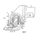
- the present Nahmaachine which is intended for sewing together fabric edges with butt seam or for piercing the fabric edges, has a housing 1 (Fig. 1) with a handle 2 (for controlling, holding and guiding the machine), mechanisms of an arcuate needle 3 and one Loop catcher 4, a device 5 for moving the machine by a stitch length and a drive shaft 6- (FIG. 2) which carries a crank 7 with which the mechanisms of the needle 3 and the loop catcher 4 and the device 5 (FIG. 1) are kinematically connected to move the machine by a stitch length.
- the arcuate needle 3 has an eye 8 at one end and is mounted on a rotatable shaft 9 (FIG. 2) which is accommodated in guides of the housing 1 in a horizontal plane.
- a rotatable shaft 9 FIG. 2
- the needle 3 carries out rotary movements in the vertical plane in the direction of the arrow shown in FIG. 2.
- the loop catcher 4 is also arch-shaped and has a hook 10 or an eye (not shown) at one of its ends, which is dependent on the technological operation carried out by the machine (for example, stitching together with a butt seam or stitching over the edges).
- the loop catcher 4 lies in the horizontal plane and is ver in the guides of the housing tically arranged rotary shaft 11 attached. When the shaft 11 rotates, the loop catcher 4 performs rotary movements in the horizontal plane in the direction indicated by arrows in FIG. 2.
- the kinematic connection of the mechanism of the needle 3 with the crank 7 of the drive shaft 6 in accordance with the embodiment variant shown in FIG. 2 contains a main rack 12 with two mutually parallel tooth surfaces 13 (upper) and 14 (lower).
- the main rack 12 is accommodated at right angles to the shaft 9 in guides 15 (FIG. 1) of the housing 1 and is moved back and forth with the aid of a rotatable toothed segment 16 (FIGS. 2, 3) which cooperates with the upper tooth surface 13.
- the lower tooth surface 14 of the toothed rack 12 acts with a gear 1? together.
- the toothed segment 16 is rotatably arranged on an axle 18 built into the housing 1 and is connected via an axle 19 to a connecting rod 20 which is connected to the crank 7.
- the rack is moved along 12 in a recess provided in the guide 22, for example, in the form of a groove, via the main rack 12 and additional rack 21.
- the additional toothed rack 21 is moved in the guide 22 at right angles to the shaft 11, to which a toothed wheel 23 which is in engagement with the teeth of this toothed rack 21 is fastened, the guide 22 between the tooth surfaces 13 and 14, as in FIG. shown lies.
- the main rack 12 is provided with a limit stop 24 for the additional rack 21, where the main rack 12 with the additional rack 21 by a spring 25, e.g. a compression spring is connected.
- a spring 25 e.g. a compression spring
- a stop 26 is attached to the housing 1, with which the shaft 27 of the loop catcher 4 interacts.
- the device 5. for moving the machine by a stitch length contains an interchangeable presser foot 28 with ends 29 bent upwards (see Fig. 1) and teeth 30 on the sole for contact with the sewing material, as well as in horizontal guides 32 of the housing accommodated and connected to each other by a web 33 supports 31.
- a finger 34 is fastened to the web 33, which engages in a profile groove 35 which is embodied on the side face of a cam 36 fastened to the drive shaft 6.
- the cam 36 with the groove 35 is a drive for the device 5, which adjusts the machine by a stitch length.
- the main rack 12 (see FIG. 4) has a lower tooth surface 14 which cooperates with the gear 17.
- a driver 37 is fastened to the main rack 12 with a vertical groove 38 in which the pin 39 of the crank 7 is accommodated.
- the crank 7 is connected to the cam 36 seated on the drive shaft 6.
- a device 40 (FIG. 5) is provided in the device 5 for regulating the step, which is fastened to supports 31, the supports in the housing not being the supports 31 as for the embodiment variant according to FIGS. 1, 3, but the housing 41 (FIG. 5) of the assembly 40 of the control unit.
- the assembly 40 of the control contains a housing 41, a crosshead hub 42 arranged in the housing 41 and movable from 0 to the maximum in the step control, and a screw 43 which is screwed into the crosshead hub 42 and has an end against a stationary one Stop 44 in the housing 41.
- the screw 43 is provided with a scale 45 of the stride lengths.
- the machine works as follows.
- the loop catcher 4 When the machine drive is switched on, the loop catcher 4 is caulked against the stop 26 (FIGS. 1, 2, 3, 4) and remains in this position until the bent needle 3 enters the loop 49 formed by the loop catcher 4 with a thread 48 . In this position, the additional rack 21 is at a certain distance from the limit stop 24.
- the bent needle 3 begins its movement into the loop 49 from the drive shaft via the crank 7, the connecting rod 20, the toothed segment 16, the main rack 12 and the toothed wheel 17.
- the spring 25 holds the loop catcher 4 in the position pressed against the limiter 26 (FIG. 6) via the additional rack 21 and the toothed wheel 23, so that the needle 3 can enter the loop 49 unhindered.
- the limit stop 24 With a further movement of the needle 3, ie with the movement of the main rack 12 to the right (see drawing in FIG. 7), the limit stop 24 approaches the additional rack 21 and begins to move it in the same direction in FIG which also moves the main rack 12.
- the additional rack 21 rotates the gear 23 as it moves, and the gear 23 rotates the loop catcher 4 to the left (see drawing, Fig. 7,8).
- the loop catcher 4 throws off the loop 49 and the needle 3, by piercing the sewing material 50, goes into it at one point and out at another (FIGS. 7, 8).
- the connecting rod 20 rotates the toothed segment 16 in the opposite direction.
- the main toothed rack 12 and the additional toothed rack 21 are moved to the left as shown in the drawing (FIG. 10) by rotating the toothed wheels 17 and 23 and turn the needle 3 counterclockwise according to the drawing and the loop catcher 4 according to the drawing to the right.
- the loop catcher 4 grips the thread 48 by forming a new loop and the needle 3 comes out of the sewing material 50.
- the movement of the additional rack 21 to the left together with the main rack 12 takes place because of the spring 25, which strives to press the additional rack 21 against the limit stop 24.
- the additional rack 21 goes somewhat away from the stop 24 (FIG. 10) due to the reaction of the tension force of the thread 48, from which a new loop is formed, on the loop catcher 4, the gear 23 and thus also on the additional rack 21
- Such a "resilient" action of the loop catcher 4 on the thread 48 precludes its breakage when a new loop is tensioned.
- the loop catcher 4 presses against the stop 26 again and stops the gear 23 and the additional rack 21. Since the main rack 12 moves further by guiding the needle 3 out of the loop catcher 4, the stop 24 goes off the additional rack 21 by an even greater distance and the needle 3 assumes the position shown in FIG. 6. The work cycle of the machine is then repeated in the order described above.
- the movement of the machine by a stitch length takes place by the cam 36 by adjustment in the profile groove 35 of the finger 34, on which the interchangeable sewing feet 28, which contact the material to be sewn, are mounted. Since the presser feet 28 are in constant engagement with the material to be sewn (thanks to the teeth on their sole), the machine housing moves in the guides gen 32 by a stolen length.
- the stitch length is regulated by screwing in or unscrewing the screw 43, which changes the position of the crosshead hub 42 in the housing 41.
- the present invention can be used for sewing together different materials with butt seam, for example, for sewing together fabric ends during dyeing, for sewing insulation on pipes, etc., and for stitching over edges on technical materials, material webs which are large in area and have a high mass will.
Landscapes
- Engineering & Computer Science (AREA)
- Textile Engineering (AREA)
- Sewing Machines And Sewing (AREA)
- Nitrogen And Oxygen Or Sulfur-Condensed Heterocyclic Ring Systems (AREA)
- Variable-Direction Aerials And Aerial Arrays (AREA)
Abstract
Applications Claiming Priority (2)
| Application Number | Priority Date | Filing Date | Title |
|---|---|---|---|
| SU4469594 | 1988-08-02 | ||
| SU884469594A SU1687678A1 (ru) | 1988-08-02 | 1988-08-02 | Швейна машина |
Publications (2)
| Publication Number | Publication Date |
|---|---|
| EP0396762A1 true EP0396762A1 (fr) | 1990-11-14 |
| EP0396762A4 EP0396762A4 (en) | 1991-01-23 |
Family
ID=21393624
Family Applications (1)
| Application Number | Title | Priority Date | Filing Date |
|---|---|---|---|
| EP19890909900 Withdrawn EP0396762A4 (en) | 1988-08-02 | 1989-07-11 | Sewing machine |
Country Status (8)
| Country | Link |
|---|---|
| EP (1) | EP0396762A4 (fr) |
| JP (1) | JPH03500730A (fr) |
| CN (1) | CN1040069A (fr) |
| AU (1) | AU4184589A (fr) |
| ES (1) | ES2014841A6 (fr) |
| FI (1) | FI901571A7 (fr) |
| SU (1) | SU1687678A1 (fr) |
| WO (1) | WO1990001579A1 (fr) |
Families Citing this family (8)
| Publication number | Priority date | Publication date | Assignee | Title |
|---|---|---|---|---|
| US5331000A (en) * | 1992-03-09 | 1994-07-19 | Sepracor Inc. | Antipyretic and analgesic methods and compositions containing optically pure R(-) ketoprofen |
| RU2283388C1 (ru) * | 2005-03-10 | 2006-09-10 | Игорь Александрович Борисов | Способ временного соединения тканей и малогабаритная швейная машина для его осуществления |
| MD4187C1 (ro) * | 2011-03-24 | 2013-06-30 | СИЛОЧ Харалампие | Procedeu de formare a cusăturilor încheiate în două fire într-un rând şi/sau mai multe rânduri de cusături în lanţ cu un singur fir, legate cu un fir suplimentar şi dispozitiv pentru realizarea acestuia la maşini de cusut |
| CN106594217B (zh) * | 2016-12-07 | 2019-11-15 | 龙南骏亚精密电路有限公司 | 一种机器人往返用驱动装置 |
| CN108149392B (zh) * | 2018-03-13 | 2023-10-20 | 钦州学院 | 便携式缝纫机 |
| CN108754900A (zh) * | 2018-07-26 | 2018-11-06 | 吴江市震宇缝制设备有限公司 | 一种缝纫机用针保护装置 |
| CN111945307B (zh) * | 2020-09-08 | 2024-08-23 | 刘乾林 | 一种单针单线印染接布机 |
| CN112144184A (zh) * | 2020-09-27 | 2020-12-29 | 黄毛牙 | 一种高端装备制造高效的缝制衣服装置 |
Family Cites Families (5)
| Publication number | Priority date | Publication date | Assignee | Title |
|---|---|---|---|---|
| BE378066A (fr) * | 1931-03-09 | |||
| US2687103A (en) * | 1952-11-18 | 1954-08-24 | Mosberg Abraham | Blindstitch attachment for sewing machines |
| DE2038501A1 (de) * | 1970-08-03 | 1972-02-10 | Karl Foerster | Rundnadel-Naehmaschine |
| DE2500461C3 (de) * | 1975-01-08 | 1979-08-16 | Fa. Maximilian Janser, 7000 Stuttgart | Nähmaschine zum Einfassen der Kanten von Bodenbelägen o.dgl |
| US4123982A (en) * | 1977-04-05 | 1978-11-07 | Bess Jr Kenneth B | Blind suturing apparatus |
-
1988
- 1988-08-02 SU SU884469594A patent/SU1687678A1/ru active
-
1989
- 1989-07-11 JP JP1509139A patent/JPH03500730A/ja active Pending
- 1989-07-11 AU AU41845/89A patent/AU4184589A/en not_active Abandoned
- 1989-07-11 WO PCT/SU1989/000191 patent/WO1990001579A1/fr not_active Ceased
- 1989-07-11 FI FI901571A patent/FI901571A7/fi not_active IP Right Cessation
- 1989-07-11 EP EP19890909900 patent/EP0396762A4/ru not_active Withdrawn
- 1989-08-01 ES ES8902729A patent/ES2014841A6/es not_active Expired - Fee Related
- 1989-08-02 CN CN89105507.XA patent/CN1040069A/zh active Pending
Also Published As
| Publication number | Publication date |
|---|---|
| FI901571A0 (fi) | 1990-03-29 |
| CN1040069A (zh) | 1990-02-28 |
| AU4184589A (en) | 1990-03-05 |
| EP0396762A4 (en) | 1991-01-23 |
| FI901571A7 (fi) | 1990-03-29 |
| JPH03500730A (ja) | 1991-02-21 |
| WO1990001579A1 (fr) | 1990-02-22 |
| ES2014841A6 (es) | 1990-07-16 |
| SU1687678A1 (ru) | 1991-10-30 |
Similar Documents
| Publication | Publication Date | Title |
|---|---|---|
| DE19620311B4 (de) | Stickmaschine | |
| DE102007026651A1 (de) | Nähmaschine sowie Betriebsverfahren für eine derartige Nähmaschine | |
| DE10002456B4 (de) | Stoffvorschubvorrichtung für Nähmaschine | |
| DE2718607B1 (de) | Naehmaschine mit einer angetriebenen Vorschubrolle | |
| DE19624260A1 (de) | Nähmaschine | |
| DE3545531C2 (fr) | ||
| DE3342391C1 (de) | Naehmaschine mit Nadel und Untertransport und einer Einrichtung zum Ansteuern eines vorbestimmten Endpunktes einer Naht | |
| EP0396762A1 (fr) | Machine a coudre | |
| DE2156316A1 (de) | Schlingenfängerantrieb für Zickzack-Nähmaschinen | |
| DE2638264B2 (de) | Nähmaschine zum Ausführen von Voroder Zierstichen auf Stoff | |
| DE3842674A1 (de) | Sich hin- und herbewegendes messerschneidgeraet mit flexiblem antriebsteil | |
| DE1660191B1 (de) | Vorrichtung zum veraenderlichen Kraeuseln von Faeden od.dgl. | |
| DE3143694C2 (de) | Vorrichtung zum Einstellen des Stoffschieber-Vorschubweges an einer Nähmaschine | |
| DE2223202C2 (de) | Nähmaschine | |
| DE6926302U (de) | Obertransportvorrichtung an naehmaschinen | |
| DE2108309B1 (de) | Doppelkettenstichnähmaschine mit einer kombinierten Vorschubeinrichtung | |
| EP0269010A2 (fr) | Tête d'agrafage | |
| DE3313831C2 (de) | Nähmaschine mit Hauptantriebswelle und Differential-Stoffschiebereinrichtung | |
| DE1785134A1 (de) | Nadelwebstuhl zum Herstellen von Baendern,Riemen,Guerteln u.dgl. | |
| EP0512145B1 (fr) | Procédé pour exécuter une couture changeant de direction | |
| DE2923570C2 (de) | Doppelkettenstich-Nähmaschine | |
| DE2154359C2 (de) | Vielnadelnähmaschine | |
| CH693383A5 (de) | Vorrichtung zum Abschneiden eines Nähfadens in einer Nähmaschine und Verwendung der Vorrichtung, um den Oberfaden nach unten zu ziehen. | |
| DE2650352C2 (de) | Nähmaschine mit einem oberhalb der Stichbildestelle angeordneten Greifer | |
| DE1037240B (de) | Naehmaschine |
Legal Events
| Date | Code | Title | Description |
|---|---|---|---|
| PUAI | Public reference made under article 153(3) epc to a published international application that has entered the european phase |
Free format text: ORIGINAL CODE: 0009012 |
|
| 17P | Request for examination filed |
Effective date: 19900328 |
|
| AK | Designated contracting states |
Kind code of ref document: A1 Designated state(s): AT BE CH DE FR GB IT LI NL SE |
|
| A4 | Supplementary search report drawn up and despatched |
Effective date: 19901206 |
|
| AK | Designated contracting states |
Kind code of ref document: A4 Designated state(s): AT BE CH DE FR GB IT LI NL SE |
|
| 17Q | First examination report despatched |
Effective date: 19920701 |
|
| STAA | Information on the status of an ep patent application or granted ep patent |
Free format text: STATUS: THE APPLICATION IS DEEMED TO BE WITHDRAWN |
|
| 18D | Application deemed to be withdrawn |
Effective date: 19921112 |