EP0397123A2 - Méthode pour la direction des courroies de fonte pour les machines à coulée continue des métaux et machine à coulée continue des métaux - Google Patents
Méthode pour la direction des courroies de fonte pour les machines à coulée continue des métaux et machine à coulée continue des métaux Download PDFInfo
- Publication number
- EP0397123A2 EP0397123A2 EP90108673A EP90108673A EP0397123A2 EP 0397123 A2 EP0397123 A2 EP 0397123A2 EP 90108673 A EP90108673 A EP 90108673A EP 90108673 A EP90108673 A EP 90108673A EP 0397123 A2 EP0397123 A2 EP 0397123A2
- Authority
- EP
- European Patent Office
- Prior art keywords
- belt
- steering
- casting
- sensing
- signal source
- Prior art date
- Legal status (The legal status is an assumption and is not a legal conclusion. Google has not performed a legal analysis and makes no representation as to the accuracy of the status listed.)
- Granted
Links
Images


Classifications
-
- B—PERFORMING OPERATIONS; TRANSPORTING
- B22—CASTING; POWDER METALLURGY
- B22D—CASTING OF METALS; CASTING OF OTHER SUBSTANCES BY THE SAME PROCESSES OR DEVICES
- B22D11/00—Continuous casting of metals, i.e. casting in indefinite lengths
- B22D11/16—Controlling or regulating processes or operations
-
- B—PERFORMING OPERATIONS; TRANSPORTING
- B22—CASTING; POWDER METALLURGY
- B22D—CASTING OF METALS; CASTING OF OTHER SUBSTANCES BY THE SAME PROCESSES OR DEVICES
- B22D11/00—Continuous casting of metals, i.e. casting in indefinite lengths
- B22D11/06—Continuous casting of metals, i.e. casting in indefinite lengths into moulds with travelling walls, e.g. with rolls, plates, belts, caterpillars
- B22D11/0605—Continuous casting of metals, i.e. casting in indefinite lengths into moulds with travelling walls, e.g. with rolls, plates, belts, caterpillars formed by two belts, e.g. Hazelett-process
-
- B—PERFORMING OPERATIONS; TRANSPORTING
- B22—CASTING; POWDER METALLURGY
- B22D—CASTING OF METALS; CASTING OF OTHER SUBSTANCES BY THE SAME PROCESSES OR DEVICES
- B22D11/00—Continuous casting of metals, i.e. casting in indefinite lengths
- B22D11/06—Continuous casting of metals, i.e. casting in indefinite lengths into moulds with travelling walls, e.g. with rolls, plates, belts, caterpillars
- B22D11/0637—Accessories therefor
- B22D11/0677—Accessories therefor for guiding, supporting or tensioning the casting belts
Definitions
- the present invention relates to the steering of long, flexible, thin endless metallic belts that revolve around pulleys of belt-type continuous metal-casting machines and which constitute at least part of the moving mold of such casting machines.
- An endless revolving flexible metallic belt employed in the continuous casting of metals should run true.
- the centerline of the belt should be juxtaposed on, and precisely revolve around, the peripheral centerlines of the fixed point or pulleys around which it is oriented.
- metallic belts usually have an imperfection, namely "camber,” i.e., a side-to-side (lateral) variation or deviation of the edge from a straight or true line caused by imperfections in the parent metal strip from which the belt is made. Consequently, the edges of these belts usually do not run true, even though flat, but have side-to-side curvature deviations in the plane of the belt, due to problems in metal strip production at the strip mill in casting and rolling of the raw strip material from which the belt is made.
- Belts in a twin-belt casting machine are normally steered by continually sensing the lateral or side-to-side position of one edge of the revolving belt while the edge passes a stationary sensor.
- the edge passes completely by the sensor during every revolution of the belt, and the continually-sensing sensor is ready to send out corrective steering signals at any time.
- a prior-art steering system will inevitably "hunt” back and forth in response to the variations or deviations of the endlessly passing cambered edge.
- a prior-art sensing and steering system is continually endeavoring (or straining) to keep the cambered-edge belt on centerline.
- This prior-art continual "hunting" sensing and steering results in needless wear of the steering mechanism. More important, the relatively wide sideways excursions of the steered belt result in worn streaks in the belt coating adjacent to the edge dams, upsetting the proper heat transfer pattern.
- the sideways excursions of the belt further impart diagonal flutes and variable tension of the belt in the moving mold, which, in combination with thermal stresses, may result in loss of contact with the freezing slab being cast, thus causing disturbance to the slab. Since the belts are the dominant moving mold surface, such disturbance is detrimental to metallurgical quality of the slab being cast.
- the tilting-pulley-steering method would tilt a pulley through a range of perhaps as much as 0.100 of an inch (2.5 mm) at the exit-pulley end of the casting machine.
- this tilt happens rapidly, the thin, flexible, revolving belt is forced into readjustment by sliding across the face of the pulley. The friction of this sliding under the normal range of belt tension results in ripples or "flutes" extending in the belt in the direction of the tension.
- a visually observable problem caused by the prior-art continual "hunting"-sensing and steering control is wear of insulative belt coatings near the edge dams 8 (FIG. 1).
- Edge dams whether moving or stationary, generally are constrained never to move sideways, whereas the steered belts have freedom to do so because they cannot be forcibly constrained without destroying them.
- the side-to-side steering excursions of the belts revolving relative to the laterally constrained edge dams have caused belt coatings to be worn, rubbed or scrubbed away by the edge dams, thus exposing areas of the belt that are subsequently exposed to molten metal when the belt is steered back the other way in the continual hunting action of the prior art.
- each belt is notched or otherwise cued fixedly at one place along or near an edge so that a steering sensor senses this notch or cue as the belt revolves.
- a first (cueing) electrical circuit fed from the sensor, recognizes this cue notch as a unique place and accordingly activates a second circuit--an electrical-processing steering-control circuit that is set up to send out steering-control instructions in response to the side-to-side lateral tracking error of the belt as a whole.
- the steering control circuit In order to reflect only the sideways tracking error of the belt as a whole (in contradistinction to the lateral tracking errors of the cambered edge of the belt), the steering control circuit only sends these steering signals to indicate the position of some one predetermined place or region on the belt following the sensing of a cue.
- This predetermined place on the belt is called the "tracking-error-sensing region" and is conveniently arranged to pass the sensor station at a time immediately or soon following the passage of the cue notch past the sensor.
- the second or electrical control circuit after being cued, then issues commands (based upon sensed tracking errors) to the mechanical steering apparatus to take corrective steering action.
- the senor does not send merely a "yes-no" signal but sends a signal that is substantially proportional to the sensed lateral tracking error of the predetermined tracking-error-sensing region on the revolving belt edge, following sensing of the cue.
- the sensing may occur at a multiplicity of closely spaced points within the predetermined tracking-error-sensing region, with extreme readings being discarded, in order to obtain a reliably consistent signal.
- the invention will be illustrated in the context of a twin-belt continuous metal-casting machine using rotating pulleys 10 as shown in FIG. 1 , though the invention can be applied to any continuous metal-casting machine employing a flexible, wide, endless moving casting belt.
- E indicates the entrance for molten metal being fed into the machine.
- C the casting cavity, U the upper carriage, L the lower carriage, and P the emerging cast metallic product.
- the invention is described in terms for example of a cue notch in the edge of a belt serving as a fixed cue signal source for initiating the steering sequence, though other kinds of cue signal source fixed to the belt are possible, for example a small elongated oval hole near the edge for optical or mechanical sensing.
- a flexible metallic casting belt 12 with weld 14 and cambered edges 16 incorporates a cue notch 18 in one edge as shown in FIG. 2 .
- the rounded shape allows the notched area of the moving belt to pass without snagging a mechanically contacting edge-sensing roller 20 (FIGS. 4 and 5 ).
- This roller sensor is rotably mounted on spring-loaded swinging arm 22 of an electrical sensing unit 24 .
- the electrical sensing unit 24 is enclosed in a protective housing 25 and incorporates an electric position-sensor and signal transmitter, here shown as a conductive-plastic rotary potentiometer 26 in a strong, waterproof housing 25 .
- This sensor-transmitter affords an output voltage corresponding to the lateral position of the moving belt edge, not merely a yes-or-no or yes-null-no signal as occurs in the prior art of which we are aware.
- the sensor unit 24 for each belt is normally placed on the inboard side of the machine. Only the sensor unit 24 for the upper casting belt is shown.
- the advantage of placing these sensors on the inboard side of the machine is that they do not impede belt replacement. They are placed near the entrance E (FIG. 4 ) so that they are located upstream from the exit so that the action of the exit pulleys (not shown in FIG. 4 ) performing belt steering does not immediately or detrimentally affect the signals from the sensing means 26 .
- the environment for each sensor unit 24 is more nearly free from cascading coolant. They are generally placed adjacent to the return reach of belt.
- An arrow 27 indicates the return travel of each revolving casting belt 12 , returning toward the entrance pulleys 10 .
- the rounded cue notch 18 in the moving belt edge 16 is an example of a fixed cue signal source. That is, the passage of this cue notch past the sensor 24 initiates (cues) belt position sampling for the current revolution of the belt.
- the sensor unit 24 may be replaced by a photo-optical device to sense the belt edge according to the variations or patterns of a light beam passing by and being variably partially obscured by the moving belt edge, thereby producing corresponding variations in an output voltage from the photo-optical sensor.
- Air sensing devices responding to the variable interruption of one or more free air streams, may also be used in lieu of the sensor units 24 .
- a photo-optical sensor or an air sensor will work with a cue notch 18 of any of several shapes, not just a rounded shape.
- a cue signal source 18 could consist of a hole in the belt, sensed by photo-optical sensor or air sensor as just described.
- a cue signal source 18 can also be provided by some intentional alteration in the appearance or physical characteristics of the belt at the cue signal source point. For instance, with a visual cue signal source, a photoelectric cell can cue (initiate) the steering sequence.
- a spot of insulative coating of non-conductive material on an otherwise conductive belt margin can cooperate with one or more electric brushes or sliding contacts, or a spot of electrically conductive material over a non-conductive belt margin, can serve as the cue signal source.
- a spot of magnetic coating on a non-magnetic belt could serve as the cue device, as can a spot of radioactive material on a belt in cooperation with a stationary receiver for the radioactive rays. None of these latter cue signal sources would involve any notch.
- the advantages of the cue notch 18 are that it is simple and rugged while enabling use of the same sensor unit 24 that senses the belt lateral position.
- the location of cue notch 18 or a cue hole can be anywhere where neither molten metal nor water normally come into contact with the belt.
- Other kinds of cue signal sources as described have more freedom of location. Visual cue signal sources might conceivably be placed anywhere on the surface of the belt.
- the cue notch 18 itself can be made the measuring place for steering control sensing if desired.
- the place 19 follows by 500 milliseconds the cue signal that indicates the passing of the notch. This one-half-second time interval is compatible with a typical speed of casting, which may be 25 feet (8 meters) per minute.
- 500 milliseconds corresponds to a distance of about 2.5 inches (about 63 millimeters), which is only a small remove in the present context.
- the reference place 19 the place on the belt where the belt edge position is sensed, could be located at some distance in time and place behind the cue notch 18 .
- a measuring place near to the notch can be repetitively identified approximately enough for present purposes with a time-delay circuit involving only a brief delay, for example not more than about 3 seconds, in preference to a more complicated distance-measuring circuit.
- This place 19 is the "tracking-error-sensing region" on the belt.
- the delay in reaching the place 19 can be in a range up to a maximum of about 15 inches from the cue notch 18 , since the camber of belts is a gradual and one-way phenomenon, not normally occurring abruptly or reversing along the length of a belt. If this broad tolerance is used, the cue notch should be placed far from the belt weld 14 , since the joining of cambered cut ends of sheet stock results in a sudden change of direction 47 at the weld (FIG. 5 ).
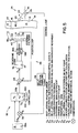
- a closed-loop control system is shown as being employed.
- the roller 20 on the swinging sensor arm 22 continuously adjusts a movable contact 29 of a potentiometer 26 , which is suitably energized by a low-voltage direct current (DC) electrical source, such as a battery or DC power supply (not shown).
- DC direct current
- the signal from the potentiometer contact 29 goes to a sampling circuit 28 labeled BELT POSITION SAMPLING LOGIC.
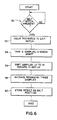
- the initial cueing signal delivered by the cue notch 18 in the belt edge at each belt revolution signal is represented at 50 in the sampling and control algorithm shown in FIG.
- a 500-millisecond delay is then provided as indicated at 52 to allow the position roller 20 to clear the cue notch 18 and to reach the predetermined sampling area 19 which is the tracking-error-sensing region on the belt.
- the sampling circuit 28 repetitively queries the potentiometer 26 for obtaining five belt-position readings in close succession, about ten milliseconds apart, though the selection of this interval is not at all critical and can be selected from a range up to about a fourth as wide as the aforesaid maximum delay range of about 3 seconds in starting the sampling.
- the sampling circuit 28 now ranks the five sample readings from low to high, as indicated at 56 , and the highest and lowest readings are discarded as being possibly the results of vagaries due to nicks, bits of dirt, or static.
- the remaining three of the five readings are averaged for providing a reliable reading (a reliable indication) of the now existing actual belt tracking position.
- This measured position value is stored in the sampling circuit 28 , as indicated at 60 in FIG. 6 , and remains stored for the remainder of the belt revolution.
- This measured position value (which may be considered as the data signal for indicating any error in belt position) is also sent as a signal F b to another comparator 30 , as shown by the arrow and legend E b .
- the measured value F b for the present belt tracking position is compared with a reference signal R b which is provided from a potentiometer 31 having a manually adjustable control knob 33A that is used by the operator to set the desired belt tracking position for operation of the casting machine 9 .
- the control-loop comparator 30 By comparing the measured value signal F b with the reference value signal R b , the control-loop comparator 30 generates a difference signal E b which represents the now existing error in the actual measured position of the revolving belt 12 .
- This error signal E b is fed into and is amplified by a proportional gain amplifier 32 labeled CONTROLLER.
- the magnitude of the now-existing-error signal E b is directly proportional to the gain K p of the amplifier 32 .
- the output signal from the controller 32 has a value V c and represents roughly the error signal E b proportionally amplified by the proportional gain factor K p .
- This proportionally amplified signal V c may also be considered to be a steering reference (or steering control input) signal. It is fed to the feedback-position-loop comparator 34 for the purpose of controlling a linear steering cylinder 42 having a piston rod 43 .
- this linear steering cylinder 42 corresponds with the linear steering cylinder shown at 72 in FIGS. 8 , 9 , and 10 of copending U.S. Serial No. 224,058 made of record on page 1 of the present application and being incorporated herein by reference.
- the cylinder piston rod 43 shown in FIG. 5 hereof for example, corresponds with the piston rod 74 shown in FIGS. 8 and 9 of said copending patent application.
- movement of the cylinder piston rod 43 in FIG. 5 turning the lever 46 , serves to steer a revolving casting belt 12 (FIGS. 1 and 4 ).
- the linear belt-steering cylinder is equipped with a potentiometer 40 having a movable contact 41 .
- This potentiometer 40 is electrically energized in a manner as described for the other potentiometer 26 .
- this potentiometer 40 is, for example, a conductive plastic potentiometer located inside of the housing of linear cylinder 42 and having its movable contact 41 moved in unison with the travel of the steering cylinder piston rod 43 .
- the movable contact 41 is being positioned at all times in accordance with the position of the piston rod 43 , and thereby this movable contact 43 provides a feedback signal voltage E c that is linearly proportional to the position of the steering cylinder rod 43 .
- the belt-steering controller 34 compares the feedback signal F c (which represents the now-existing position of the steering piston rod 43 ) with the steering controller input signal V c , and this controller 34 provides a steering control output voltage E c which is fed to a final electrical processor 36 labeled DEADBAND LOGIC, which finally activates hydraulic solenoid valves 38A and 38B to move cylinder 42 to the calculated position V c .
- Equation (1) The overall control operation or algorithm of the belt-steering controller 34 plus amplifier 32 is based on classical PID (proportional integral-differential) concepts as set forth in Equation (1) below, with one important modification, which will be explained later.
- V s theoretically desired offset--i.e., where the piston rod 43 should be when the system reaches a stable, error-free condition and assuming that there be a linear relationship between the now-existing piston rod position and the now-existing belt position.
- E b belt-position error signal from control-loop comparator 30 .
- K i integral gain of the controller 32 .
- K d derivative gain of the controller 32 .
- K p proportional gain of the controller 32 .
- the controller 32 In order to provide the two components of the output voltage V c in Equation (1) represented by the integral term K i ⁇ E b dt and by the differential term K d ⁇ dE b/ dt , the controller 32 has data storage capability for remembering previous values of E b which have recently been fed into this controller. Thus, this controller 32 determines the integral value of E b dt as well as the differential value dE b/ dt which indicates the now-existing time rate of change of the error voltage signal E b .
- the controller 32 has manual knobs or other controls 33B , 33C , and 33D for adjusting the desired values for the overall proportional gain K d , the integral coefficient K i and the differential coefflcient K d , depending upon the overall operational characteristics of the whole steering control system 45 shown in FIGS. 4 , 5 , and 6 .
- K p , K i , and K d are adjusted at setup by trial and error by the aforesaid knobs or other controls. Too low a K p results in sluggish response; too high a K p results in overshoot and consequent hunting.
- the final processor/controller 36 supplies electrical power to actuate a pair of solenoid operated valves 38A and 38B which are connected to the linear steering cylinder 42 for feeding hydraulic liquid thereto for controlling the piston rod position. If the control signal V c is negative, the solenoid valves 38A and 38B are operated in a relationship for retracting the piston rod 43 . If the control signal V c is positive, these solenoid valves are operated in the opposite relationship for extending the piston rod 43 . Moreover, the amount by which this piston rod is retracted or extended is a direct function of the magnitude of the steering control signal V c .
- the DEADBAND LOGIC controller 36 provides a physical tolerance zone. This controller 36 is programmed not to actuate the solenoid valves 38A and 38B unless and until the control signal V c exceeds a modest predetermined threshold value. This threshold value is manually adjustable, and the controller 36 includes a control 37 by which the operator can adjust the setting of this modest tolerance threshold for minimizing unduly repetitive cycling of these solenoid valves while also obtaining the desired precision in belt steering which is afforded by the control system 45 .
- V s offset term (which is the theoretically desired position of the piston rod)
- V s ′ the value of the piston rod
- Our algorithm adjusts for the (in practice) non-linear relationship between the position F c of the piston rod 43 and the belt lateral position as indicated by the feedback signal F b .
- V s is then to be modifled to V s ′ through algebraic operations with two adjustable terms to compensate for mechanical non-linearity.
- V s ′ R b (1 ⁇ .005 G x H) where R b is the lateral-belt-position set point. G is set to an integer between 1 and 10 by trial and error at setup, using an adjustment not shown, and then left alone.
- the additional factor H is made to vary according to the magnitude of the error E b . If the error E b persists between 15 and 30 mils (0.4 to 0.8 mm), then H is set at 1, using an adjustment not shown. If the error persists between 30 and 90 mils (0.8 mm to 2.3 mm), H is set at 2. If the persisting error is greater than 90 mils (2.3 mm), H is set at 3. The minus sign in the ⁇ sign in formula (2) is applied for persistent errors E b occurring in one direction of belt lateral tracking, while the plus sign is applied for such errors occurring in the opposite direction.
- the end result of employing the above-described method and system embodying the present invention is that the belts 12 are steered in such a way as to obtain speedy correction of belt tracking position while minimizing hunting action of the steering mechanism 38A , 38B , 42 , 43 .
- Observed tracking errors are cut by a factor of around 6, as compared with the best prior art of which we are aware.
- steered revolving belts wandered regularly in the range of ⁇ 0.062 of an inch ( ⁇ 1.6 mm). Indeed, we observed three times that amount of belt excursions in one installation.
- the maximum range of lateral belt excursion which was observed in one all-day experimental test was ⁇ 0.010 of an inch.
Landscapes
- Engineering & Computer Science (AREA)
- Mechanical Engineering (AREA)
- Continuous Casting (AREA)
Applications Claiming Priority (2)
| Application Number | Priority Date | Filing Date | Title |
|---|---|---|---|
| US07/348,976 US4940076A (en) | 1989-05-09 | 1989-05-09 | Method and apparatus for steering casting belts of continuous metal-casting machines |
| US348976 | 1989-05-09 |
Publications (3)
| Publication Number | Publication Date |
|---|---|
| EP0397123A2 true EP0397123A2 (fr) | 1990-11-14 |
| EP0397123A3 EP0397123A3 (fr) | 1992-06-03 |
| EP0397123B1 EP0397123B1 (fr) | 1995-12-13 |
Family
ID=23370371
Family Applications (1)
| Application Number | Title | Priority Date | Filing Date |
|---|---|---|---|
| EP90108673A Expired - Lifetime EP0397123B1 (fr) | 1989-05-09 | 1990-05-08 | Méthode pour la direction des courroies de fonte pour les machines à coulée continue des métaux et machine à coulée continue des métaux |
Country Status (6)
| Country | Link |
|---|---|
| US (1) | US4940076A (fr) |
| EP (1) | EP0397123B1 (fr) |
| AT (1) | ATE131426T1 (fr) |
| CA (1) | CA2015865C (fr) |
| DE (1) | DE69024093T2 (fr) |
| WO (1) | WO1990013378A1 (fr) |
Cited By (4)
| Publication number | Priority date | Publication date | Assignee | Title |
|---|---|---|---|---|
| EP0868953A3 (fr) * | 1997-03-04 | 1999-02-03 | Hazelett Strip-Casting Corporation | Procédé et appareil de guidage d'une courroie de coulée dans une machine de coulée continue de métal |
| EP1777021A1 (fr) * | 2005-10-19 | 2007-04-25 | Hazelett Strip-Casting Corporation | Appareil a coussin d'air cylindrique, sustentateur non rotatif permettant de soutenir et de guider un tapis de coulee souple sans fin dans l'entree d'une machine de coulee de metaux en continu |
| WO2008134302A1 (fr) * | 2007-04-26 | 2008-11-06 | Nucor Corporation | Procédé et système de suivi et de positionnement de dalles coulées continues |
| US11254066B2 (en) | 2019-03-22 | 2022-02-22 | Dukane Ias, Llc | Apparatus for fabricating an elastic nonwoven material |
Families Citing this family (14)
| Publication number | Priority date | Publication date | Assignee | Title |
|---|---|---|---|---|
| US5086827A (en) * | 1990-12-06 | 1992-02-11 | Hazelett Strip-Casting Corporation | Method and apparatus for sensing the condition of casting belt and belt coating in a continuous metal casting machine |
| US5547891A (en) * | 1992-07-01 | 1996-08-20 | Texas Instruments Incorporated | Structural modification to enhance DRAM gate oxide quality |
| US5355688A (en) * | 1993-03-23 | 1994-10-18 | Shape, Inc. | Heat pump and air conditioning system incorporating thermal storage |
| AUPO928797A0 (en) * | 1997-09-19 | 1997-10-09 | Bhp Steel (Jla) Pty Limited | Strip steering |
| AU735336B2 (en) * | 1997-09-19 | 2001-07-05 | Bluescope Steel Limited | Strip steering |
| US6764559B2 (en) * | 2002-11-15 | 2004-07-20 | Commonwealth Industries, Inc. | Aluminum automotive frame members |
| US7467639B2 (en) * | 2003-03-28 | 2008-12-23 | General Electric Company | Systems and methods for controlling gas flow |
| US20060042727A1 (en) * | 2004-08-27 | 2006-03-02 | Zhong Li | Aluminum automotive structural members |
| US20080202646A1 (en) * | 2004-08-27 | 2008-08-28 | Zhong Li | Aluminum automotive structural members |
| US7163047B2 (en) | 2005-03-21 | 2007-01-16 | Nucor Corporation | Pinch roll apparatus and method for operating the same |
| US7168478B2 (en) * | 2005-06-28 | 2007-01-30 | Nucor Corporation | Method of making thin cast strip using twin-roll caster and apparatus therefor |
| US20080041501A1 (en) * | 2006-08-16 | 2008-02-21 | Commonwealth Industries, Inc. | Aluminum automotive heat shields |
| CN102717583B (zh) * | 2011-10-26 | 2015-02-04 | 湖北联合天诚防伪技术股份有限公司 | 压辊安全控制装置 |
| CN108067595B (zh) * | 2017-08-04 | 2020-05-26 | 骆驼集团蓄电池研究院有限公司 | 一种铅酸蓄电池正极铅坯成型工艺及专用设备 |
Family Cites Families (10)
| Publication number | Priority date | Publication date | Assignee | Title |
|---|---|---|---|---|
| CA651153A (en) * | 1962-10-30 | J. Foye John | Distributor for feeding molten metal | |
| GB810402A (en) * | 1957-02-15 | 1959-03-18 | Albert Leimer | Improvements in or relating to devices for maintaining the position of a travelling belt or the like |
| NL237185A (fr) * | 1958-03-17 | |||
| US3908881A (en) * | 1973-03-21 | 1975-09-30 | Gary D Mccann | Centering sensor and controller |
| US3963068A (en) * | 1973-04-12 | 1976-06-15 | Hazelett Strip-Casting Corporation | Symmetrical synchronized belt-steering system and apparatus for twin-belt continuous metal casting machines |
| US4061222A (en) * | 1975-07-09 | 1977-12-06 | Eastman Kodak Company | Web tracking apparatus |
| US4135664A (en) * | 1977-03-04 | 1979-01-23 | Hurletronaltair, Inc. | Lateral register control system and method |
| US4557372A (en) * | 1984-08-13 | 1985-12-10 | The Mead Corporation | Belt system with alignment apparatus |
| JPS6349355A (ja) * | 1986-08-19 | 1988-03-02 | Ube Ind Ltd | ロータリダイカストマシンの回転テーブル駆動制御方法 |
| JPS63101054A (ja) * | 1986-10-16 | 1988-05-06 | Hitachi Ltd | ベルト式連続鋳造装置 |
-
1989
- 1989-05-09 US US07/348,976 patent/US4940076A/en not_active Expired - Lifetime
-
1990
- 1990-05-01 CA CA002015865A patent/CA2015865C/fr not_active Expired - Lifetime
- 1990-05-08 DE DE69024093T patent/DE69024093T2/de not_active Expired - Fee Related
- 1990-05-08 WO PCT/US1990/002561 patent/WO1990013378A1/fr not_active Ceased
- 1990-05-08 AT AT90108673T patent/ATE131426T1/de not_active IP Right Cessation
- 1990-05-08 EP EP90108673A patent/EP0397123B1/fr not_active Expired - Lifetime
Cited By (6)
| Publication number | Priority date | Publication date | Assignee | Title |
|---|---|---|---|---|
| EP0868953A3 (fr) * | 1997-03-04 | 1999-02-03 | Hazelett Strip-Casting Corporation | Procédé et appareil de guidage d'une courroie de coulée dans une machine de coulée continue de métal |
| AU737517B2 (en) * | 1997-03-04 | 2001-08-23 | Hazelett Strip-Casting Corporation | Steering, tensing and driving a revolving casting belt using an exit-pulley drum for achieving all three functions |
| EP1777021A1 (fr) * | 2005-10-19 | 2007-04-25 | Hazelett Strip-Casting Corporation | Appareil a coussin d'air cylindrique, sustentateur non rotatif permettant de soutenir et de guider un tapis de coulee souple sans fin dans l'entree d'une machine de coulee de metaux en continu |
| WO2008134302A1 (fr) * | 2007-04-26 | 2008-11-06 | Nucor Corporation | Procédé et système de suivi et de positionnement de dalles coulées continues |
| US7806164B2 (en) | 2007-04-26 | 2010-10-05 | Nucor Corporation | Method and system for tracking and positioning continuous cast slabs |
| US11254066B2 (en) | 2019-03-22 | 2022-02-22 | Dukane Ias, Llc | Apparatus for fabricating an elastic nonwoven material |
Also Published As
| Publication number | Publication date |
|---|---|
| DE69024093T2 (de) | 1996-05-09 |
| EP0397123A3 (fr) | 1992-06-03 |
| DE69024093D1 (de) | 1996-01-25 |
| US4940076A (en) | 1990-07-10 |
| ATE131426T1 (de) | 1995-12-15 |
| WO1990013378A1 (fr) | 1990-11-15 |
| CA2015865C (fr) | 2001-12-18 |
| EP0397123B1 (fr) | 1995-12-13 |
| CA2015865A1 (fr) | 1990-11-09 |
Similar Documents
| Publication | Publication Date | Title |
|---|---|---|
| US4940076A (en) | Method and apparatus for steering casting belts of continuous metal-casting machines | |
| KR100531125B1 (ko) | 강철 슬래브 제조방법 및 장치 | |
| US3921697A (en) | Method and apparatus for controlling the operating conditions in continuous metal casting machines having a revolving endless casting belt | |
| EP1040066B1 (fr) | Appareil de guidage de bande et procede associe pour le maintien de la position laterale | |
| US3864973A (en) | Method and apparatus for determining the operating conditions in continuous metal casting machines of the type having a revolving endless casting belt | |
| US4030531A (en) | Method and apparatus for monitoring and obviating deformations of continuous castings | |
| EP0095352B1 (fr) | Procédé et dispositif pour la production de bandes métalliques solidifiées rapidement par un système à deux cylindres | |
| KR19990001794A (ko) | 열연권취기의 스트립 미단 자동정지 제어방법 | |
| US8205662B2 (en) | Method for the continuous casting of a metal strand | |
| EP0259876B1 (fr) | Procédé pour commande automatique du niveau pour des machines à coulée continue à double bande | |
| JP4541501B2 (ja) | ストリップ上方に設けられている二つの遮蔽部材のための調節方法およびこの方法のための装置 | |
| JPH0513746B2 (fr) | ||
| KR100476058B1 (ko) | 연속주조공정의 주편 절단기 제어장치 | |
| JPS57139457A (en) | Method for controlling position and shape of perfect solidification point in width direction of ingot in continuous casting | |
| JPH0513747B2 (fr) | ||
| KR20010103234A (ko) | 스트립 형상 교정기의 폭방향 두께 편차 교정장치 | |
| JPS5823547A (ja) | 溶融金属急冷法により片ロ−ル法で製造する薄帯板の巾方向板厚制御方法 | |
| CA1039924A (fr) | Methode et machine de coulee continue sur courroie sans fin | |
| JPH05287478A (ja) | 溶融金属メッキストリップ製造方法及び装置 | |
| WO1997014638A1 (fr) | Appareil de guidage de bande et procede associe | |
| JP2593349Y2 (ja) | 連続鋳造用鋳型の鋳片支持装置 | |
| SU952424A1 (ru) | Способ настройки машины непрерывного лить заготовок | |
| CA1121719A (fr) | Moteurs et vis-meres jumeles de positionnement des butees de piece et d'entrainement d'un piston de presse | |
| JPH0117768B2 (fr) | ||
| JPH0660374B2 (ja) | 鋼帯処理ラインにおける鋼帯の振動防止装置 |
Legal Events
| Date | Code | Title | Description |
|---|---|---|---|
| PUAI | Public reference made under article 153(3) epc to a published international application that has entered the european phase |
Free format text: ORIGINAL CODE: 0009012 |
|
| AK | Designated contracting states |
Kind code of ref document: A2 Designated state(s): AT BE DE FR GB IT |
|
| 17P | Request for examination filed |
Effective date: 19901228 |
|
| PUAL | Search report despatched |
Free format text: ORIGINAL CODE: 0009013 |
|
| AK | Designated contracting states |
Kind code of ref document: A3 Designated state(s): AT BE DE FR GB IT |
|
| 17Q | First examination report despatched |
Effective date: 19940117 |
|
| GRAA | (expected) grant |
Free format text: ORIGINAL CODE: 0009210 |
|
| AK | Designated contracting states |
Kind code of ref document: B1 Designated state(s): AT BE DE FR GB IT |
|
| REF | Corresponds to: |
Ref document number: 131426 Country of ref document: AT Date of ref document: 19951215 Kind code of ref document: T |
|
| REF | Corresponds to: |
Ref document number: 69024093 Country of ref document: DE Date of ref document: 19960125 |
|
| ITF | It: translation for a ep patent filed | ||
| ET | Fr: translation filed | ||
| PLBE | No opposition filed within time limit |
Free format text: ORIGINAL CODE: 0009261 |
|
| STAA | Information on the status of an ep patent application or granted ep patent |
Free format text: STATUS: NO OPPOSITION FILED WITHIN TIME LIMIT |
|
| 26N | No opposition filed | ||
| REG | Reference to a national code |
Ref country code: GB Ref legal event code: IF02 |
|
| PGFP | Annual fee paid to national office [announced via postgrant information from national office to epo] |
Ref country code: DE Payment date: 20060508 Year of fee payment: 17 |
|
| PGFP | Annual fee paid to national office [announced via postgrant information from national office to epo] |
Ref country code: AT Payment date: 20060511 Year of fee payment: 17 |
|
| PG25 | Lapsed in a contracting state [announced via postgrant information from national office to epo] |
Ref country code: AT Free format text: LAPSE BECAUSE OF NON-PAYMENT OF DUE FEES Effective date: 20070508 |
|
| PG25 | Lapsed in a contracting state [announced via postgrant information from national office to epo] |
Ref country code: DE Free format text: LAPSE BECAUSE OF NON-PAYMENT OF DUE FEES Effective date: 20071201 |
|
| PGFP | Annual fee paid to national office [announced via postgrant information from national office to epo] |
Ref country code: IT Payment date: 20080527 Year of fee payment: 19 |
|
| PGFP | Annual fee paid to national office [announced via postgrant information from national office to epo] |
Ref country code: GB Payment date: 20080514 Year of fee payment: 19 |
|
| PGFP | Annual fee paid to national office [announced via postgrant information from national office to epo] |
Ref country code: BE Payment date: 20080709 Year of fee payment: 19 |
|
| PGFP | Annual fee paid to national office [announced via postgrant information from national office to epo] |
Ref country code: FR Payment date: 20090515 Year of fee payment: 20 |
|
| BERE | Be: lapsed |
Owner name: *HAZELETT STRIP-CASTING CORP. Effective date: 20090531 |
|
| GBPC | Gb: european patent ceased through non-payment of renewal fee |
Effective date: 20090508 |
|
| PG25 | Lapsed in a contracting state [announced via postgrant information from national office to epo] |
Ref country code: GB Free format text: LAPSE BECAUSE OF NON-PAYMENT OF DUE FEES Effective date: 20090508 |
|
| PG25 | Lapsed in a contracting state [announced via postgrant information from national office to epo] |
Ref country code: BE Free format text: LAPSE BECAUSE OF NON-PAYMENT OF DUE FEES Effective date: 20090531 |
|
| PG25 | Lapsed in a contracting state [announced via postgrant information from national office to epo] |
Ref country code: IT Free format text: LAPSE BECAUSE OF NON-PAYMENT OF DUE FEES Effective date: 20090508 |