EP0397257B1 - Dispositif d'affouragement pour animaux - Google Patents
Dispositif d'affouragement pour animaux Download PDFInfo
- Publication number
- EP0397257B1 EP0397257B1 EP90201137A EP90201137A EP0397257B1 EP 0397257 B1 EP0397257 B1 EP 0397257B1 EP 90201137 A EP90201137 A EP 90201137A EP 90201137 A EP90201137 A EP 90201137A EP 0397257 B1 EP0397257 B1 EP 0397257B1
- Authority
- EP
- European Patent Office
- Prior art keywords
- frame
- feeding
- fence
- feeding fence
- head
- Prior art date
- Legal status (The legal status is an assumption and is not a legal conclusion. Google has not performed a legal analysis and makes no representation as to the accuracy of the status listed.)
- Expired - Lifetime
Links
Images


Classifications
-
- A—HUMAN NECESSITIES
- A01—AGRICULTURE; FORESTRY; ANIMAL HUSBANDRY; HUNTING; TRAPPING; FISHING
- A01K—ANIMAL HUSBANDRY; AVICULTURE; APICULTURE; PISCICULTURE; FISHING; REARING OR BREEDING ANIMALS, NOT OTHERWISE PROVIDED FOR; NEW BREEDS OF ANIMALS
- A01K1/00—Housing animals; Equipment therefor
- A01K1/10—Feed racks
- A01K1/105—Movable feed barriers
-
- A—HUMAN NECESSITIES
- A01—AGRICULTURE; FORESTRY; ANIMAL HUSBANDRY; HUNTING; TRAPPING; FISHING
- A01K—ANIMAL HUSBANDRY; AVICULTURE; APICULTURE; PISCICULTURE; FISHING; REARING OR BREEDING ANIMALS, NOT OTHERWISE PROVIDED FOR; NEW BREEDS OF ANIMALS
- A01K5/00—Feeding devices for stock or game ; Feeding wagons; Feeding stacks
Definitions
- the invention relates to a device for feeding amimals as defined in the introductory part of claim 1.
- the invention has for its object to improve the device of the kind set forth above.
- the motor drive means prevent movement of the feeding fence in the non-active state, the animals cannot move the feeding fence forward by themselves. With the switch timer the farmer can determine the distance over which the fence is displaced. After all the fodder has been eaten, the same motor drive means actuated in reverse direction move the feeding devices without any effort on the side of the farmer, back to the begin position.
- the support means preferably comprise a number of wheels mounted rotatably on the frame.
- the feeding fence can hereby be moved very lightly over the ground surface.
- the feeding fence When the step of claim 3 is thereby applied the feeding fence will displace reciprocally parallel to itself in a certain manner so that for a very long period the feeding fence remains in the correct position on the ground surface.
- a simple embodiment of the device according to the invention is characterized in claim 4.
- the actual feeding fence itself no longer contains any moving parts.
- the separate drive device engages externally onto the actual feeding fence in simple manner.
- a particularly effective embodiment is further characterized in claim 5.
- the respective drive devices of the feeding fences disposed opposite one another can hereby be at least partially combined so that an economic construction can be achieved.
- the drive device can be embodied in many different ways.
- a favourable embodiment is characterized in claim 6.
- a screw driving is operationally reliable and comparatively insensitive to dirtying so that a long, reliable operation is ensured.
- this drive device is used with two feeding fences disposed opposite one another the step of claim 7 is preferably applied.
- the screwed spindles can still be arranged in favourable manner at a level located considerably above the ground, without decreasing the accessibility of the space between the feeding fences. At a height above the ground the dirtying of the screwed spindles is in a favourable manner considerably less.
- a device for feeding animals having two feeding fences displaceable over the ground surface and disposed opposite one another.
- the displacing means in the known device are formed by rails arranged in the ground surface and slide pieces co-acting therewith on the frames of the feeding fences. Means are provided to lock the slide to the rails after each adjustment of the fence.
- Fig. 1 shows in perspective view two feeding fences according to the invention disposed opposite one another.
- Fig. 2 shows in partly broken away view a detail of the drive device of the feeding fence of fig. 1.
- Fig. 3 shows a preferred embodiment of the device according to the invention.
- Fig. 4 shows a perspective view of two feeding fences disposed opposite one another as in fig. 3, in operation.
- Fig. 5 shows a partly broken away detail view along arrow V in fig. 3.
- Fig. 6 shows in perspective view corresponding with fig. 1 another embodiment of the feeding fence according to the invention.
- Fig. 7 shows schematically another embodiment of a drive device for the feeding fence according to the invention.
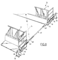
- Fig. 8 shows a partly perspective view of yet another embodiment of the device according to the invention.
- the feeding fence device 1 of fig. 1 comprises two feeding fences 2 and 3 disposed opposite one another. Each of these feeding fence 2, 3 comprises a frame 4 on which is placed a fence 5.
- the fence 5 comprises a number of bars between which are defined respective openings 6 through which animals can push their head in order to take up fodder placed in front of the fence.
- the feeding fences are of the so-called self-catching type, wherein present close to each opening 6 is a bar 24 which can swivel by means of a hinge 25.
- animals such as cows
- animals can push their head through the opening 6 at the top.
- the neck of the animal comes against the portion of the swivel bar 24 lying below the hinge 25, whereby the swivel bar 24 is swivelled into a vertical position.
- the bottom end of the swivel bar 24 co-acts via a slot 26 in the frame 4 with locking means which lock the swivel bar 24 in the vertical position.
- control means (not shown) are further present wherewith the locks can be disengaged so that the swivel bars 24 are once again released and the animals can withdraw their head from the openings 6.
- Each feeding fence 2, 3 rests by means of slide pieces directly on the ground surface and can thus slide thereover.
- These slide pieces may be steel slide shoes or may be formed for example by nylon blocks.
- a drive device 11 shown in more detail in fig. 2 comprises a reversible electromotor 12 which drives rotatably a fixedly mounted rod 14 via reduction gearing 13. Wound around this rod 14 are cables 15 which are trained about cable pulleys 16 arranged fixedly adjacent to the respective feeding fences. The ends of each cable 15 are fastened to a support 17 connected fixedly to the relevant feeding fence. As shown in fig. 2 the support 17 also bears a guide 18 which fits into a slot 19 formed in the ground.
- the upper part of the cable 15 is fastened to the support 17 of the feeding fence 3.
- the upper part 15 is therefore pulled towards the rod 14 and the fence 3 displaced forwards.
- the fence 2 is fastened in similar manner to the relevant cable, but to the lower part, so that when the rod 14 is rotated in the direction indicated the fences 2, 3 are pulled towards one another.
- fig. 1 shows the rod 14 extends over the full length of the two feeding fences 2, 3 and a similar cable construction is arranged at the opposite end so that the feeding fences 2, 3 are driven at both ends, thus ensuring a stable operation.
- each support 17 of the feeding fences 2, 3 Connected to each support 17 of the feeding fences 2, 3 is a cover plate 20 which covers the slot 19 formed in the ground in all positions of the relevant feeding fences between the wholly moved forward and moved back positions. Dirtying of the drive device by fodder remnants and manure is prevented in this manner.
- the drive gear 13 with motor 12 and associated components is mounted in a pit 21 arranged in the floor and closed off using a cover 22.
- the rod 14 mounted at either end on a fixed point forms a support element relative to which the frame of the feeding fences can be driven in forward and rearward direction by the drive device 11.
- the motor 12 of the drive device 11 is switched on in reverse direction whereby the feeding fences are moved away from one another into their mutually most remote position. Fresh fodder can then be placed between the fences.
- the feeding fence 75 shown in fig. 3 comprises a frame 76 wherein in a manner to be described later a lengthwise shaft 77 is mounted. This lengthwise shaft bears a number of wheels 78 connected fixedly thereto which form the support means wherewith the frame 76 supports directly on the ground surface.
- the lengthwise shaft 77 can be driven in a manner to be further described using a drive device 79.
- This comprises a reversible electromotor which is fed via an electric cable 80 fastened to the ceiling of the shed where the device according to the invention is in use.
- the feeding fence 75 comprises a number of feeding openings 81 which are bounded on one side by a swivel bar 82, wherein an animal that pushes its head through the opening 81 in order to begin feeding is locked into the fence 75.
- Fig. 4 shows the feeding fence 75 of fig. 3 in a device together with an identical feeding fence 83 disposed opposite.
- a quantity of fodder 86 is heaped between the feeding fences 75 and 83.
- cows 85 push their head through the above mentioned openings 81 in order to be able to reach the heaped fodder 86.
- the cows 85 support therein with their front legs on the floor plate 84 which is fixedly connected to the frame of the relevant feeding fence. Any force applied to the fence by the pushing of the cows 85 is directly compensated by the reaction force exerted by the front legs so that a closed system of forces results and the feeding fences cannot be pushed over. Because of the short path of force the construction of the feeding fences can be comparatively light.
- the drive device 79 of the feeding fences as shown in fig. 3 and 4 is shown in more detail in fig. 5.
- This drive device 79 comprises a reversible electromotor 87 mounted on a reduction gearing 88.
- a gear wheel 89 which via a chain 90 is in driving connection with a gear wheel 91 that is mounted fixedly on the lengthwise shaft 77.
- the lengthwise shaft 77 is connected rotatably to the frame 76 by means of bearing blocks 92 which consist of two mutually clamped plastic blocks, for instance of nylon, leaving free a bearing channel.
- Welded fixedly to the frame 76 is a V-shaped support plate 93 against which the bearing block 92 rests, thus being able to transmit the vertical forces.
- a reaction rod 94 Arranged close to the chain transmission and between the shaft 77 and the drive gear 88 is a reaction rod 94 which on one side supports by means of a nylon block 95 on the shaft 77 and on the other side supports against a plate 96 connected to the reduction gearing 88.
- the reaction rod directly takes up the chain forces so that these do not have to be transmitted via the frame 76, whereby it can remain light.
- a casing 97 Arranged around the drive gear 88 and the motor 87 is a casing 97. In the top part of the casing 97 is housed a switch unit 98 which is provided with push-buttons 99 with which the motor 87 can be actuated.
- the switch unit 98 can be incorporated an adjustable switch timer which switches on the motor 87 for a determined duration of time after pressing of one of the push-buttons 99.
- This switch-on period determines the distance over which the feeding fence is displaced.
- the farmer can establish the desired movement distance each time by means of the switch -on duration.
- the feeding fence device of fig. 6 corresponds in large measure with that shown in fig. 1.
- the device 30 likewise comprises two feeding fences 31 and 32 which can be moved towards and away from one another by drive devices close to each lengthwise end of each feeding fence 31, 32.
- Each drive device 33 here comprises a support 34 mounted fixedly to the ground and bearing a drive gear 36 driven by a reversible electromotor 35.
- a screwed spindle 37 is mounted fixedly, that is, non-rotatably.
- the drive gear 36 comprises a rotatably mounted nut which engages on the screwed spindle 37 and which can be set into rotation via a reduction gearing by the motor 35.
- the motors 35 of the drive devices 33 of a fence 31 or 32 are in any case driven synchronously.
- all four motors of all four drive gears are driven synchronously, wherein the rotation direction is of course such that when the drive devices are switched on simultaneously the feeding fences 31, 32 move towards or away from one another.
- the drive device 40 here comprises a transmission 41 connected fixedly to the ground which, in the manner already described with reference to fig. 6, can in the first place move reciprocally via a motor 42 a screwed spindle 43 connected fixedly to the fence.
- the transmission 41 is however embodied such that it can drive a vertical output shaft 44.
- Via a right-angle transmission 45 the shaft 44 drives a horizontal shaft 50 which, again via a right-angle transmission 46 close to the opposite end of the relevant feeding fence, drives a vertical shaft 51, which forms the input shaft of a transmission 47 corresponding to the transmission 41.
- this transmission 47 thus drives the screwed spindle 48 in the same manner as the screwed spindle 43 is driven. In this way the feeding fence is driven synchronously at both ends in certain manner.
- the right-angle transmission 45 is further embodied such that it has a second output shaft 49 which extends to a similar drive device of a similar feeding fence disposed opposite.
- This drive device can have its own electromotor, wherein the shaft 49 serves to synchronize the two drivings.
- the feeding fence device 55 shown in fig. 8 once again comprises two oppositely disposed feeding fences 56, 57.
- the drive device 58 in this embodiment comprises a casing connected fixedly to the ground wherein a transmission 60 is housed which is drivably coupled to a reversible electromotor 59.
- the output shaft of the transmission 60 is formed by a screwed spindle 61 which engages into nuts 62, 63 connected fixedly to the side fence of the feeding fence 57. Through rotation of the screwed spindle 61 using the electromotor 59 the feeding fence 57 can thus be moved reciprocally.
- the feeding fence 56 comprises similar nuts 66 into which engages a screwed spindle 65 which is bearing mounted with its end in a support 64 connected fixedly to the ground.
- This screwed spindle 65 is driven by the same driving 58 using a coupling rod 67.
- the coupling rod 67 is coupled at one end to the screwed spindle 61 by means of a universal joint 68 and with its other end to the screwed spindle 65 by means of a releasable coupling.
- This releasable coupling comprises a slide piece 69 which is arranged slidably but not rotatably on the rod 67 and is provided internally with gripping means which grip onto coupling elements 70 at the end of the screwed spindle 66.
- the two feeding fences 56, 57 are driven synchronously by the one driving 58.
- the coupling rod 67 is released from the screwed spindle 65 and can be folded upward to the position designated with 71.
- the space between the two feeding fences 56, 57 can hereby be made easily accessible for placing fodder between the feeding fences. Due to the placing of the screwed spindles at a level considerably above the ground they remain free of dirt.
- the embodiments shown relate to the most usual fences disposed opposite one another in twos.
- a single feeding fence can also be employed, for instance with a driving as shown in fig. 6.
Landscapes
- Life Sciences & Earth Sciences (AREA)
- Environmental Sciences (AREA)
- Animal Husbandry (AREA)
- Biodiversity & Conservation Biology (AREA)
- Zoology (AREA)
- Birds (AREA)
- Feeding And Watering For Cattle Raising And Animal Husbandry (AREA)
- Catching Or Destruction (AREA)
- Apparatuses For Bulk Treatment Of Fruits And Vegetables And Apparatuses For Preparing Feeds (AREA)
- Housing For Livestock And Birds (AREA)
- Vending Machines For Individual Products (AREA)
- Feeding Of Workpieces (AREA)
- Turning (AREA)
- Electrical Discharge Machining, Electrochemical Machining, And Combined Machining (AREA)
- Heat-Pump Type And Storage Water Heaters (AREA)
- Crystals, And After-Treatments Of Crystals (AREA)
Claims (12)
- Dispositif d'affouragement d'animaux comprenant au moins une grille d'affouragement et un portique reposant, par l'intermédiaire de moyens de support, sur le sol, et étant équipé d'une plaque de plancher s'étendant selon un faible écart au-dessus de la surface du sol, à l'arrière du portique, en direction d'un bord arrière en contact avec le sol, plaque qui peut supporter au moins les pattes avant des animaux qui ont introduit leur tête à travers des ouvertures délimitées par des paires de barres fixées au portique, dans lequel la grille d'affouragement est du type à auto-verrouillage, possédant, à proximité de chaque ouverture, une barre pivotante s'encliquetant derrière la tête de l'animal une fois que la tête a été introduite à travers l'ouverture, comportant des moyens d'entraînement à moteur réversible destinés à déplacer la grille d'affouragement sur la surface du sol et des moyens de commande prévus pour actionner les moyens d'entraînement à moteur dans une direction sélectionnée, caractérisé en ce que les moyens d'entraînement à moteur sont disposés de telle sorte qu'à l'état non-actif, le déplacement de la grille d'affouragement soit empêché, les moyens de commande comprenant une minuterie à touches réglable mettant en route les moyens d'entraînement à moteur.
- Dispositif selon la revendication 1, caractérisé en ce que les moyens de support comprennent une pluralité de roues montées rotatives sur le portique.
- Dispositif selon la revendication 2, caractérisé en ce que la pluralité de roues est montée de façon fixe sur une tige longitudinale continue montée de façon rotative, les moyens d'entraînement étant engagés sur la tige longitudinale.
- Dispositif selon la revendication 1, caractérisé en ce que les moyens de support comprennent une pluralité de supports coulissants fixés sur le portique et en ce que les moyens d'entraînement sont en prise, d'un côté, sur le portique et, sur l'autre côté, sur un élément de support relié de façon fixe à la surface du sol.
- Dispositif selon la revendication 1, caractérisé en ce que les moyens de support comprennent une pluralité de supports coulissants fixés sur le portique et en ce que les moyens d'entraînement sont en prise, d'un côté, sur le portique et, de l'autre côté, sur un portique d'une grille d'affouragement sensiblement identique située en regard, afin de déplacer simultanément ces grilles d'affouragement en direction ou à l'opposé l'une de l'autre.
- Dispositif selon l'une quelconque des revendications précédentes, caractérisé en ce que le dispositif d'entraînement est un dispositif d'entraînement à tige filetée.
- Dispositif selon la revendication 6, caractérisé en ce qu'au moins un écrou est monté sur le portique, en ce qu'une tige filetée du dispositif d'entraînement à tige filetée s'étend à travers l'écrou et est reliée, pour un entraînement rotatif, à un mécanisme d'entraînement monté sur l'élément de support, et dans lequel une tige filetée correspondante de la grille d'affouragement située en regard, pourvue d'un filetage opposé, est couplée au mécanisme d'entraînement.
- Dispositif selon la revendication 7, caractérisé en ce que les tiges filetées sont couplées par une bielle d'accouplement démontable.
- Dispositif selon la revendication 8, caractérisé en ce que la bielle d'accouplement est reliée à l'une des tiges filetées par un joint à rotule et, à son extrémité opposée, porte une gaine coulissante mais non rotative qui est pourvue, à l'intérieur, de moyens de serrage qui sont en prise avec des éléments d'accouplement à l'extrémité de la tige filetée située en regard.
- Dispositif selon l'une des revendications précédentes, caractérisé en ce qu'un dispositif d'entraînement est disposé de part et d'autre du portique.
- Dispositif selon la revendication 2 ou 3, caractérisé en ce que les roues ont un diamètre supérieur à 20 cm.
- Dispositif selon la revendication 11, caractérisé en ce que les roues ont un diamètre de 40 cm.
Applications Claiming Priority (2)
| Application Number | Priority Date | Filing Date | Title |
|---|---|---|---|
| NL8901158A NL8901158A (nl) | 1989-05-08 | 1989-05-08 | Verplaatsbaar voerhek. |
| NL8901158 | 1989-05-08 |
Publications (2)
| Publication Number | Publication Date |
|---|---|
| EP0397257A1 EP0397257A1 (fr) | 1990-11-14 |
| EP0397257B1 true EP0397257B1 (fr) | 1994-10-05 |
Family
ID=19854617
Family Applications (1)
| Application Number | Title | Priority Date | Filing Date |
|---|---|---|---|
| EP90201137A Expired - Lifetime EP0397257B1 (fr) | 1989-05-08 | 1990-05-04 | Dispositif d'affouragement pour animaux |
Country Status (24)
| Country | Link |
|---|---|
| US (1) | US5054430A (fr) |
| EP (1) | EP0397257B1 (fr) |
| AT (1) | ATE112448T1 (fr) |
| BG (1) | BG61061B2 (fr) |
| CA (1) | CA2016053C (fr) |
| CZ (1) | CZ278721B6 (fr) |
| DD (1) | DD300066A5 (fr) |
| DE (1) | DE69013048T2 (fr) |
| DK (1) | DK0397257T3 (fr) |
| ES (1) | ES2060928T3 (fr) |
| FI (1) | FI91706C (fr) |
| HU (1) | HU205236B (fr) |
| IE (1) | IE66982B1 (fr) |
| LT (1) | LT3763B (fr) |
| LV (1) | LV10554B (fr) |
| NL (1) | NL8901158A (fr) |
| NO (1) | NO176381C (fr) |
| PL (1) | PL163218B1 (fr) |
| PT (1) | PT93981B (fr) |
| RO (1) | RO111531B1 (fr) |
| SK (1) | SK277833B6 (fr) |
| SU (1) | SU1837753A3 (fr) |
| UA (1) | UA13458A (fr) |
| YU (1) | YU47977B (fr) |
Families Citing this family (30)
| Publication number | Priority date | Publication date | Assignee | Title |
|---|---|---|---|---|
| BE1006372A4 (nl) * | 1991-12-17 | 1994-08-02 | Weelink Johannes M W | Verplaatsbaar voerhek. |
| DE4216488C1 (en) * | 1992-05-19 | 1993-03-04 | Josef 4418 Nordwalde De Mussmann | Manger with fodder frame grid bars - has fodder frame profiled stabiliser at lower end, facing stall floor or ground |
| CA2073091A1 (fr) * | 1992-07-03 | 1994-01-04 | James V. Blazek | Barriere a betail |
| NL9300501A (nl) * | 1993-03-22 | 1994-10-17 | Johannes Martinus Willibrordus | Stal met voersysteem. |
| NL9300614A (nl) * | 1993-04-07 | 1994-11-01 | Johannes Martinus Willibrordus | Verplaatsbaar voerhek. |
| GB2278990B (en) * | 1993-06-10 | 1997-05-14 | Eric Francis Arthur Comley | Animal restraining apparatus and method |
| NL9401505A (nl) * | 1994-09-16 | 1996-05-01 | G J Van Laar | Voerheksamenstel. |
| NL9402169A (nl) * | 1994-12-20 | 1996-08-01 | Johannes Martinus Willibrordus | Overbrenging en van een dergelijke overbrenging voorzien verplaatsbaar voerhek. |
| WO1996019106A1 (fr) * | 1994-12-20 | 1996-06-27 | Weelink Johannes M W | Systeme de transmission et barriere mobile equipee de ce systeme pour l'alimentation des animaux en stabulation |
| NL1000636C2 (en) * | 1994-12-20 | 1996-06-20 | Johannes Martinus Willibrordus | Movable feed fence assembly with ratchet type transmission |
| AT502U1 (de) * | 1994-12-30 | 1995-12-27 | Felder Michael | Vorrichtung zum fuettern von tieren |
| NL1007247C2 (nl) | 1997-10-09 | 1999-04-12 | Weelink Johannes M W | Voederhek. |
| CA2253305C (fr) * | 1998-11-10 | 2005-02-08 | Douglas R. Strankman | Appareil d'alimentation de ratelier cornadis a tete mobile |
| US6601536B2 (en) * | 2001-08-10 | 2003-08-05 | Dale R. Sprik | Livestock feeder |
| EP1500327B1 (fr) * | 2003-07-04 | 2009-02-11 | Southern Pharmaceutical Co Ltd | Stalle pour bétail |
| US7685968B2 (en) * | 2005-01-28 | 2010-03-30 | Cooper James E | Livestock feed scraper |
| FI119275B (fi) * | 2007-04-13 | 2008-09-30 | Arkkitehtuuritoimisto Jouni Pi | Ruokintalaitteisto |
| DK2637495T3 (en) * | 2010-11-12 | 2017-05-01 | Gea Farm Technologies Gmbh | SELF-LOCKING DANGERS |
| US8919286B2 (en) * | 2012-07-19 | 2014-12-30 | Progressive Products, Inc. | Modular baled hay feeding system and method for livestock |
| ES2477090B1 (es) * | 2012-12-14 | 2015-09-08 | Francisco NAYA ZAMORA | Comedero desmontable para ganado ovino y caprino para paca rectangular y cilíndrica |
| USD773286S1 (en) | 2014-11-26 | 2016-12-06 | Tags4all Global Inc. | Rail bracket |
| US9374980B1 (en) * | 2015-02-16 | 2016-06-28 | Little Shell Enterprises, Inc. | Cattle feeder |
| RU2672497C2 (ru) * | 2015-02-27 | 2018-11-15 | Геа Фарм Текнолоджиз Гмбх | Самозапирающееся ограждение кормового стола |
| USD852610S1 (en) | 2016-04-25 | 2019-07-02 | Tags4all Global Inc. | Rail bracket |
| CN108670486B (zh) * | 2018-04-26 | 2024-04-30 | 西宁市畜牧兽医站 | 一种生猪治疗保定栏 |
| CN109220819B (zh) * | 2018-09-17 | 2024-04-16 | 天津农学院 | 一种移动式畜牧养殖用围栏及其应用 |
| CN109197654A (zh) * | 2018-11-13 | 2019-01-15 | 新泰市天信农牧发展有限公司 | 一种可调节式肉鸭养殖笼 |
| WO2021050780A1 (fr) | 2019-09-10 | 2021-03-18 | Perdue Farms, Inc. | Système d'entraînement pour un enclos à volailles et/ou porcs |
| CN114097637B (zh) * | 2021-12-20 | 2023-06-27 | 杨凌秾福农牧科技股份有限公司 | 一种牧场翻推料机器人及其使用方法 |
| CN115530083A (zh) * | 2022-09-16 | 2022-12-30 | 吉林省佰强科技有限责任公司 | 一种肉牛养殖的监测系统 |
Family Cites Families (8)
| Publication number | Priority date | Publication date | Assignee | Title |
|---|---|---|---|---|
| GB1054211A (fr) * | 1900-01-01 | |||
| US3620192A (en) * | 1970-03-19 | 1971-11-16 | James R Taylor | Animal actuated silo feeding gate |
| CA921781A (en) * | 1971-12-08 | 1973-02-27 | D. Stirling Leroy | Cattle feeder |
| US4009687A (en) * | 1975-09-08 | 1977-03-01 | Korthals John G | Roughage feeder unit |
| US4148278A (en) * | 1977-10-25 | 1979-04-10 | Haybuster Manufacturing, Inc. | Self feeding bunk or barrier |
| EP0043098A1 (fr) * | 1980-06-26 | 1982-01-06 | B. Strautmann & Söhne GmbH & Co. | Dispositif pour déplacer du fourrage ensilé en blocs |
| NL8101597A (nl) * | 1981-03-31 | 1982-10-18 | Johannes Martinus Willibrordus | Voederhok. |
| IT1203884B (it) * | 1986-04-16 | 1989-02-23 | Lentzen Paul | Collaro snodato per mangiatoia |
-
1989
- 1989-05-08 NL NL8901158A patent/NL8901158A/nl not_active Application Discontinuation
-
1990
- 1990-04-27 IE IE154590A patent/IE66982B1/en not_active IP Right Cessation
- 1990-05-03 US US07/520,063 patent/US5054430A/en not_active Expired - Fee Related
- 1990-05-04 ES ES90201137T patent/ES2060928T3/es not_active Expired - Lifetime
- 1990-05-04 DK DK90201137.8T patent/DK0397257T3/da active
- 1990-05-04 EP EP90201137A patent/EP0397257B1/fr not_active Expired - Lifetime
- 1990-05-04 HU HU902676A patent/HU205236B/hu not_active IP Right Cessation
- 1990-05-04 AT AT90201137T patent/ATE112448T1/de not_active IP Right Cessation
- 1990-05-04 CA CA002016053A patent/CA2016053C/fr not_active Expired - Fee Related
- 1990-05-04 DE DE69013048T patent/DE69013048T2/de not_active Expired - Fee Related
- 1990-05-07 SU SU904743845A patent/SU1837753A3/ru active
- 1990-05-07 UA UA4743845A patent/UA13458A/uk unknown
- 1990-05-07 SK SK2250-90A patent/SK277833B6/sk unknown
- 1990-05-07 BG BG091943A patent/BG61061B2/bg unknown
- 1990-05-07 CZ CS902250A patent/CZ278721B6/cs unknown
- 1990-05-07 YU YU89290A patent/YU47977B/sh unknown
- 1990-05-07 NO NO902015A patent/NO176381C/no unknown
- 1990-05-07 FI FI902282A patent/FI91706C/fi not_active IP Right Cessation
- 1990-05-07 RO RO145009A patent/RO111531B1/ro unknown
- 1990-05-07 DD DD340440A patent/DD300066A5/de unknown
- 1990-05-08 PL PL90285092A patent/PL163218B1/pl unknown
- 1990-05-08 PT PT93981A patent/PT93981B/pt not_active IP Right Cessation
-
1993
- 1993-12-03 LV LVP-93-1307A patent/LV10554B/lv unknown
-
1994
- 1994-01-31 LT LTIP1850A patent/LT3763B/lt not_active IP Right Cessation
Also Published As
Similar Documents
| Publication | Publication Date | Title |
|---|---|---|
| EP0397257B1 (fr) | Dispositif d'affouragement pour animaux | |
| US5054431A (en) | Adjustable animal feeder | |
| US4419963A (en) | Feeding railing | |
| US5505160A (en) | Feed distributing apparatus | |
| US4027628A (en) | Automatic feeding system for gestating livestock | |
| EP0608032A2 (fr) | Dispositif d'alimentation | |
| EP0627160B1 (fr) | Dispositif et procédé pour placer l'alimentation à la portée des animaux | |
| US3465725A (en) | Stock feed loader for feeding bunks | |
| SU140636A1 (ru) | Кормораздатчик длч широкогабаритных птичников | |
| US5467737A (en) | Stable with feeding system | |
| RU2009639C1 (ru) | Устройство для раздачи корма | |
| GB2037559A (en) | Dispensing granular materials | |
| CN121314987B (zh) | 畜牧饲喂槽清洁装置 | |
| SU938855A1 (ru) | Установка дл раздачи корма | |
| SU1665997A1 (ru) | Кормораздатчик | |
| SU1168158A1 (ru) | Устройство дл раздачи корма | |
| SU816451A2 (ru) | Установка дл раздачи кормов живот-НыМ | |
| CA2130233C (fr) | Appareil distributeur d'aliments | |
| KR940004499Y1 (ko) | 사료 공급 장치 | |
| SI9010892A (sl) | Naprava za krmiljenje živali | |
| EP0959671A1 (fr) | Cornadis d'affouragement | |
| DE102010041910B4 (de) | Vorrichtung und Verfahren zum Aufbereiten und Verteilen von Tierfutter | |
| SU1093306A1 (ru) | Кормораздатчик | |
| SU1282831A2 (ru) | Установка дл содержани животных |
Legal Events
| Date | Code | Title | Description |
|---|---|---|---|
| PUAI | Public reference made under article 153(3) epc to a published international application that has entered the european phase |
Free format text: ORIGINAL CODE: 0009012 |
|
| AK | Designated contracting states |
Kind code of ref document: A1 Designated state(s): AT BE CH DE DK ES FR GB GR IT LI LU NL SE |
|
| RAP1 | Party data changed (applicant data changed or rights of an application transferred) |
Owner name: WEELINK, JOHANNES MARTINUS WILLIBRORDUS |
|
| 17P | Request for examination filed |
Effective date: 19910510 |
|
| 17Q | First examination report despatched |
Effective date: 19920311 |
|
| GRAA | (expected) grant |
Free format text: ORIGINAL CODE: 0009210 |
|
| AK | Designated contracting states |
Kind code of ref document: B1 Designated state(s): AT BE CH DE DK ES FR GB GR IT LI LU NL SE |
|
| REF | Corresponds to: |
Ref document number: 112448 Country of ref document: AT Date of ref document: 19941015 Kind code of ref document: T |
|
| REF | Corresponds to: |
Ref document number: 69013048 Country of ref document: DE Date of ref document: 19941110 |
|
| ET | Fr: translation filed | ||
| REG | Reference to a national code |
Ref country code: ES Ref legal event code: FG2A Ref document number: 2060928 Country of ref document: ES Kind code of ref document: T3 |
|
| ITF | It: translation for a ep patent filed | ||
| REG | Reference to a national code |
Ref country code: DK Ref legal event code: T3 |
|
| EAL | Se: european patent in force in sweden |
Ref document number: 90201137.8 |
|
| REG | Reference to a national code |
Ref country code: GR Ref legal event code: FG4A Free format text: 3014538 |
|
| PLBE | No opposition filed within time limit |
Free format text: ORIGINAL CODE: 0009261 |
|
| STAA | Information on the status of an ep patent application or granted ep patent |
Free format text: STATUS: NO OPPOSITION FILED WITHIN TIME LIMIT |
|
| 26N | No opposition filed | ||
| PG25 | Lapsed in a contracting state [announced via postgrant information from national office to epo] |
Ref country code: FR Effective date: 19960229 |
|
| REG | Reference to a national code |
Ref country code: FR Ref legal event code: ST |
|
| REG | Reference to a national code |
Ref country code: FR Ref legal event code: ST |
|
| REG | Reference to a national code |
Ref country code: FR Ref legal event code: FC Ref country code: FR Ref legal event code: RN |
|
| REG | Reference to a national code |
Ref country code: FR Ref legal event code: D3 |
|
| PGFP | Annual fee paid to national office [announced via postgrant information from national office to epo] |
Ref country code: GR Payment date: 19970716 Year of fee payment: 8 |
|
| PG25 | Lapsed in a contracting state [announced via postgrant information from national office to epo] |
Ref country code: GR Free format text: LAPSE BECAUSE OF NON-PAYMENT OF DUE FEES Effective date: 19980531 |
|
| PGFP | Annual fee paid to national office [announced via postgrant information from national office to epo] |
Ref country code: LU Payment date: 19980922 Year of fee payment: 9 Ref country code: SE Payment date: 19980922 Year of fee payment: 9 |
|
| PGFP | Annual fee paid to national office [announced via postgrant information from national office to epo] |
Ref country code: AT Payment date: 19980929 Year of fee payment: 9 |
|
| PGFP | Annual fee paid to national office [announced via postgrant information from national office to epo] |
Ref country code: ES Payment date: 19980930 Year of fee payment: 9 |
|
| PGFP | Annual fee paid to national office [announced via postgrant information from national office to epo] |
Ref country code: CH Payment date: 19981007 Year of fee payment: 9 |
|
| PG25 | Lapsed in a contracting state [announced via postgrant information from national office to epo] |
Ref country code: LU Free format text: LAPSE BECAUSE OF NON-PAYMENT OF DUE FEES Effective date: 19990504 Ref country code: AT Free format text: LAPSE BECAUSE OF NON-PAYMENT OF DUE FEES Effective date: 19990504 |
|
| PG25 | Lapsed in a contracting state [announced via postgrant information from national office to epo] |
Ref country code: SE Free format text: LAPSE BECAUSE OF NON-PAYMENT OF DUE FEES Effective date: 19990505 Ref country code: ES Free format text: LAPSE BECAUSE OF EXPIRATION OF PROTECTION Effective date: 19990505 |
|
| PG25 | Lapsed in a contracting state [announced via postgrant information from national office to epo] |
Ref country code: LI Free format text: LAPSE BECAUSE OF NON-PAYMENT OF DUE FEES Effective date: 19990531 Ref country code: CH Free format text: LAPSE BECAUSE OF NON-PAYMENT OF DUE FEES Effective date: 19990531 |
|
| PGFP | Annual fee paid to national office [announced via postgrant information from national office to epo] |
Ref country code: FR Payment date: 19991116 Year of fee payment: 10 |
|
| REG | Reference to a national code |
Ref country code: CH Ref legal event code: PL |
|
| EUG | Se: european patent has lapsed |
Ref document number: 90201137.8 |
|
| REG | Reference to a national code |
Ref country code: FR Ref legal event code: ST |
|
| REG | Reference to a national code |
Ref country code: ES Ref legal event code: FD2A Effective date: 20010601 |
|
| REG | Reference to a national code |
Ref country code: GB Ref legal event code: IF02 |
|
| PGFP | Annual fee paid to national office [announced via postgrant information from national office to epo] |
Ref country code: BE Payment date: 20041125 Year of fee payment: 15 |
|
| PGFP | Annual fee paid to national office [announced via postgrant information from national office to epo] |
Ref country code: DE Payment date: 20041129 Year of fee payment: 15 |
|
| PGFP | Annual fee paid to national office [announced via postgrant information from national office to epo] |
Ref country code: DK Payment date: 20041130 Year of fee payment: 15 Ref country code: NL Payment date: 20041130 Year of fee payment: 15 |
|
| PG25 | Lapsed in a contracting state [announced via postgrant information from national office to epo] |
Ref country code: IT Free format text: LAPSE BECAUSE OF NON-PAYMENT OF DUE FEES;WARNING: LAPSES OF ITALIAN PATENTS WITH EFFECTIVE DATE BEFORE 2007 MAY HAVE OCCURRED AT ANY TIME BEFORE 2007. THE CORRECT EFFECTIVE DATE MAY BE DIFFERENT FROM THE ONE RECORDED. Effective date: 20050504 |
|
| PG25 | Lapsed in a contracting state [announced via postgrant information from national office to epo] |
Ref country code: DK Free format text: LAPSE BECAUSE OF NON-PAYMENT OF DUE FEES Effective date: 20050531 Ref country code: BE Free format text: LAPSE BECAUSE OF NON-PAYMENT OF DUE FEES Effective date: 20050531 |
|
| PGFP | Annual fee paid to national office [announced via postgrant information from national office to epo] |
Ref country code: GB Payment date: 20051026 Year of fee payment: 16 |
|
| BERE | Be: lapsed |
Owner name: *WEELINK JOHANNES MARTINUS WILLIBRORDUS Effective date: 20050531 |
|
| PG25 | Lapsed in a contracting state [announced via postgrant information from national office to epo] |
Ref country code: DE Free format text: LAPSE BECAUSE OF NON-PAYMENT OF DUE FEES Effective date: 20051201 Ref country code: NL Free format text: LAPSE BECAUSE OF NON-PAYMENT OF DUE FEES Effective date: 20051201 |
|
| NLV4 | Nl: lapsed or anulled due to non-payment of the annual fee |
Effective date: 20051201 |
|
| PG25 | Lapsed in a contracting state [announced via postgrant information from national office to epo] |
Ref country code: GB Free format text: LAPSE BECAUSE OF NON-PAYMENT OF DUE FEES Effective date: 20060504 |
|
| REG | Reference to a national code |
Ref country code: DK Ref legal event code: EBP |
|
| GBPC | Gb: european patent ceased through non-payment of renewal fee |
Effective date: 20060504 |
|
| BERE | Be: lapsed |
Owner name: *WEELINK JOHANNES MARTINUS WILLIBRORDUS Effective date: 20050531 |