EP0397330A2 - Fahrzeug-Antriebssteuervorrichtungsverfahren - Google Patents
Fahrzeug-Antriebssteuervorrichtungsverfahren Download PDFInfo
- Publication number
- EP0397330A2 EP0397330A2 EP90304063A EP90304063A EP0397330A2 EP 0397330 A2 EP0397330 A2 EP 0397330A2 EP 90304063 A EP90304063 A EP 90304063A EP 90304063 A EP90304063 A EP 90304063A EP 0397330 A2 EP0397330 A2 EP 0397330A2
- Authority
- EP
- European Patent Office
- Prior art keywords
- wheel
- spin
- predetermined
- engine
- brake
- Prior art date
- Legal status (The legal status is an assumption and is not a legal conclusion. Google has not performed a legal analysis and makes no representation as to the accuracy of the status listed.)
- Granted
Links
- 238000000034 method Methods 0.000 title claims abstract description 18
- 230000036461 convulsion Effects 0.000 claims abstract description 11
- 230000003044 adaptive effect Effects 0.000 claims abstract description 4
- 230000001133 acceleration Effects 0.000 claims description 32
- 230000001276 controlling effect Effects 0.000 claims description 10
- 230000001105 regulatory effect Effects 0.000 claims description 2
- 238000011084 recovery Methods 0.000 claims 3
- 238000009987 spinning Methods 0.000 abstract description 15
- 238000012937 correction Methods 0.000 description 24
- 230000006870 function Effects 0.000 description 15
- 230000000977 initiatory effect Effects 0.000 description 10
- 238000010586 diagram Methods 0.000 description 8
- 230000009467 reduction Effects 0.000 description 7
- 239000012530 fluid Substances 0.000 description 5
- 230000014509 gene expression Effects 0.000 description 5
- 230000004044 response Effects 0.000 description 4
- 230000001143 conditioned effect Effects 0.000 description 3
- 230000003247 decreasing effect Effects 0.000 description 3
- 230000008569 process Effects 0.000 description 3
- 230000009471 action Effects 0.000 description 2
- 238000012544 monitoring process Methods 0.000 description 2
- 238000012546 transfer Methods 0.000 description 2
- 230000008901 benefit Effects 0.000 description 1
- 230000008859 change Effects 0.000 description 1
- 238000002485 combustion reaction Methods 0.000 description 1
- 238000004891 communication Methods 0.000 description 1
- 230000006866 deterioration Effects 0.000 description 1
- 238000001914 filtration Methods 0.000 description 1
- 230000010365 information processing Effects 0.000 description 1
- 238000012545 processing Methods 0.000 description 1
Images



Classifications
-
- B—PERFORMING OPERATIONS; TRANSPORTING
- B60—VEHICLES IN GENERAL
- B60T—VEHICLE BRAKE CONTROL SYSTEMS OR PARTS THEREOF; BRAKE CONTROL SYSTEMS OR PARTS THEREOF, IN GENERAL; ARRANGEMENT OF BRAKING ELEMENTS ON VEHICLES IN GENERAL; PORTABLE DEVICES FOR PREVENTING UNWANTED MOVEMENT OF VEHICLES; VEHICLE MODIFICATIONS TO FACILITATE COOLING OF BRAKES
- B60T8/00—Arrangements for adjusting wheel-braking force to meet varying vehicular or ground-surface conditions, e.g. limiting or varying distribution of braking force
- B60T8/17—Using electrical or electronic regulation means to control braking
- B60T8/175—Brake regulation specially adapted to prevent excessive wheel spin during vehicle acceleration, e.g. for traction control
-
- B—PERFORMING OPERATIONS; TRANSPORTING
- B60—VEHICLES IN GENERAL
- B60T—VEHICLE BRAKE CONTROL SYSTEMS OR PARTS THEREOF; BRAKE CONTROL SYSTEMS OR PARTS THEREOF, IN GENERAL; ARRANGEMENT OF BRAKING ELEMENTS ON VEHICLES IN GENERAL; PORTABLE DEVICES FOR PREVENTING UNWANTED MOVEMENT OF VEHICLES; VEHICLE MODIFICATIONS TO FACILITATE COOLING OF BRAKES
- B60T8/00—Arrangements for adjusting wheel-braking force to meet varying vehicular or ground-surface conditions, e.g. limiting or varying distribution of braking force
- B60T8/32—Arrangements for adjusting wheel-braking force to meet varying vehicular or ground-surface conditions, e.g. limiting or varying distribution of braking force responsive to a speed condition, e.g. acceleration or deceleration
- B60T8/34—Arrangements for adjusting wheel-braking force to meet varying vehicular or ground-surface conditions, e.g. limiting or varying distribution of braking force responsive to a speed condition, e.g. acceleration or deceleration having a fluid pressure regulator responsive to a speed condition
- B60T8/48—Arrangements for adjusting wheel-braking force to meet varying vehicular or ground-surface conditions, e.g. limiting or varying distribution of braking force responsive to a speed condition, e.g. acceleration or deceleration having a fluid pressure regulator responsive to a speed condition connecting the brake actuator to an alternative or additional source of fluid pressure, e.g. traction control systems
-
- B—PERFORMING OPERATIONS; TRANSPORTING
- B60—VEHICLES IN GENERAL
- B60T—VEHICLE BRAKE CONTROL SYSTEMS OR PARTS THEREOF; BRAKE CONTROL SYSTEMS OR PARTS THEREOF, IN GENERAL; ARRANGEMENT OF BRAKING ELEMENTS ON VEHICLES IN GENERAL; PORTABLE DEVICES FOR PREVENTING UNWANTED MOVEMENT OF VEHICLES; VEHICLE MODIFICATIONS TO FACILITATE COOLING OF BRAKES
- B60T2230/00—Monitoring, detecting special vehicle behaviour; Counteracting thereof
- B60T2230/04—Jerk, soft-stop; Anti-jerk, reduction of pitch or nose-dive when braking
Definitions
- This invention relates to a vehicle traction control method and, more particularly to such a method which provides for such control by control of both the brakes of the driven wheels and engine torque output.
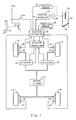
- the application of brake pressure to limit the spin of a driven wheel is made adaptive to the torque demand on the engine. This is accomplished by increasing the brake pressure when an excessive spin condition is sensed at a rate that is proportional to a parameter related to engine torque. Thus for low engine torque values, the brake pressure is ramped at a low rate. This action prevents harshness in the vehicle operation such as when manoeuvring in a parking lot, driveway or in other low throttle applications. For high engine torque values, the brake pressure is ramped at a high rate. This action provides good control of spin during hard accelerations.
- the ball screw actuator 72 is a high efficiency actuator so that the linear ball screw 74, gear train 70 and the motor output shaft are reverse driven by the hydraulic pressure acting on the piston 78 when it is greater than the torque output of the DC troque motor 68 until the hydraulic pressure is reduced to a level where it is overcome or offset by the torque output of the DC torque motor 68.
- digital computer of Figure 3 may take any conventional form, one such form may be the single chip Motorola microcomputer MC-68HC11. Alternatively, multiple processors or other circuit forms may be employed. For example, a separate microcomputer may be employed to measure wheel speed and develop various wheel state variables.
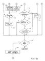
- the spin ratio of the left front driven wheel 10 is determined by the expression (V lf - V lr )/V lf where V lf and V lr are the determined wheel velocities of the left side wheels 10 and 14 respectively
- the spin ratio of the front driven wheel 12 is determined by the expression (V rf - V rr )/V rf where V rf and V rr are the determined wheel velocities of the right side wheels 12 and 16, respectively.
- spin is based upon the driven and undriven wheels on the same side of the vehicle.
- the program evaluates the status of the brake switch 50 ⁇ 97> and the status of the manually operated disable switch 54 ⁇ 98>.
- the sensed closure of either one of these switches represents a condition not requiring acceleration slip control and the program exits the routine.
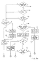
- the program continues to evaluate the wheel variables to determine if brake actuation is required.
- the initial step in this process is to determine the brake motor current correction factor to be used in controlling brake pressure after the initial control of brake pressure in accordance with this invention.
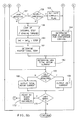
- the brake control routine Upon completion of the mode determination routine, the brake control routine is entered ( Figure 6). The brake control routine first checks for brake pedal application ⁇ 136>, a disable condition ⁇ 138>, or a lack of either wheel's TCA flag being set ⁇ 140>. If any of the above conditions are satisfied, brake pressure from both actuators 24,26 will be released. This is done by applying reverse current to both DC torque motors 68 for a set period of time represented by T interrupt intervals ⁇ 142,144,145>. All flags used in brake control are also cleared ⁇ 147>. The reverse current on the DC torque motors 68 returns the pistons 78 in the actuators 24,26 to their home positions and opens valve members 86, allowing normal braking function.
- a proportional brake control term having a value that is also based on engine torque, but which is modified by other vehicle parameters such as wheel spin ratio and wheel acceleration ⁇ 161>.
- the total motor current is then determined by adding together the proportional and integral terms ⁇ 162>. Assuming a jolt current is not required ⁇ 165>, the determined total motor current is outputted to the appropriate actuator controller 43 ⁇ 166>.
- I L and I R are the current commands to the actuators 24 and 26 and which represent the brake pressure at the respective front wheel, K1 and K2 are scaling factors that are typically equal and which relate motor current to the engine torque being absorbed by the brakes 18,20.
- the routine also determines engine output torque T E by use of a lookup table storing the predetermined relationship between engine output torque and engine speed and throttle position ⁇ 176>. At this point, if neither actuator 24,26 is active, and a Torque Control Active (TQCA) flag is not set ⁇ 178,180> the routine is exited. If either actuator 24,26 is active, and the TQCA flag has not been previously set, a throttle initiation sequence ⁇ 184,186> is entered. This sequence sets an initial value of torque desired T D from the engine to be the current engine torque T E minus an amount related to spin, vehicle acceleration and engine torque ⁇ 184>. This sequence puts an upper limit on engine output torque until the controlled brake pressure is low enough to justify return of engine power. For example, the upper limit is set higher for higher values of vehicle acceleration and set lower for higher spin ratios. During the initiation sequence, the TQCA flag is set ⁇ 180>.
- T R F i (T b - T K ).
- T K represents an acceptable level of engine torque that can be absorbed by the brakes 18,20.
- the scale factor F has a value less than one, such as 0.2 with F1 associated with a single spinning wheel being less that F2 associated with two spinning wheels.
- a position of the auxiliary throttle valve 38 is determined that will cause the engine torque to achieve the desired value ⁇ 192>. This may be done by using a series of look up tables storing the predetermined relationship between engine output torque and throttle position, engine speed and desired torque or by other means. If in the process of throttle control the auxiliary throttle valve position reaches a fully open position while a torque increase is being requested ⁇ 194>, the TQCA flag is cleared ⁇ 196> and motor current set to zero ⁇ 197>. (This condition may not occur until after both actuators 24,26 have been released). Otherwise, the routine outputs the determined auxiliary throttle valve position ⁇ 198>. After the throttle position is commanded, the routine is exited.
Landscapes
- Engineering & Computer Science (AREA)
- Transportation (AREA)
- Mechanical Engineering (AREA)
- Physics & Mathematics (AREA)
- Fluid Mechanics (AREA)
- Chemical & Material Sciences (AREA)
- Combustion & Propulsion (AREA)
- Regulating Braking Force (AREA)
Applications Claiming Priority (2)
| Application Number | Priority Date | Filing Date | Title |
|---|---|---|---|
| US07/350,242 US5014202A (en) | 1989-05-11 | 1989-05-11 | Vehicle traction control system |
| US350242 | 1989-05-11 |
Publications (3)
| Publication Number | Publication Date |
|---|---|
| EP0397330A2 true EP0397330A2 (de) | 1990-11-14 |
| EP0397330A3 EP0397330A3 (de) | 1992-01-08 |
| EP0397330B1 EP0397330B1 (de) | 1994-06-08 |
Family
ID=23375848
Family Applications (1)
| Application Number | Title | Priority Date | Filing Date |
|---|---|---|---|
| EP90304063A Expired - Lifetime EP0397330B1 (de) | 1989-05-11 | 1990-04-17 | Fahrzeug-Antriebssteuervorrichtungsverfahren |
Country Status (4)
| Country | Link |
|---|---|
| US (1) | US5014202A (de) |
| EP (1) | EP0397330B1 (de) |
| JP (1) | JPH0790760B2 (de) |
| DE (1) | DE69009586T2 (de) |
Cited By (3)
| Publication number | Priority date | Publication date | Assignee | Title |
|---|---|---|---|---|
| EP0557965A1 (de) * | 1992-02-24 | 1993-09-01 | Sumitomo Electric Industries, Limited | Vorrichtung zur Aktivierung/Desaktivierung einer Antriebsschlupfsteuerung |
| WO1994004385A1 (en) * | 1992-08-25 | 1994-03-03 | Allied-Signal, Inc. | Wheel traction control for automotive vehicle |
| EP0641697A3 (de) * | 1993-09-07 | 1996-01-17 | Lucas Ind Plc | Anordnung und Verfahren zur Resonanzsteuerung in einem bremsbetätigten Antriebsschlupfregelsystem. |
Families Citing this family (24)
| Publication number | Priority date | Publication date | Assignee | Title |
|---|---|---|---|---|
| JPH03284429A (ja) * | 1990-03-30 | 1991-12-16 | Mazda Motor Corp | 車両のスリップ制御装置 |
| US5184299A (en) * | 1990-05-31 | 1993-02-02 | General Motors Corporation | Antilock brake system motor speed control |
| US5341298A (en) * | 1992-08-25 | 1994-08-23 | Allied-Signal Inc. | Throttle traction control for automotive vehicle |
| JPH08119005A (ja) * | 1994-10-27 | 1996-05-14 | Nippondenso Co Ltd | 車両制御装置 |
| US5774821A (en) | 1994-11-25 | 1998-06-30 | Itt Automotive Europe Gmbh | System for driving stability control |
| US5711024A (en) | 1994-11-25 | 1998-01-20 | Itt Automotive Europe Gmbh | System for controlling yaw moment based on an estimated coefficient of friction |
| US5732377A (en) | 1994-11-25 | 1998-03-24 | Itt Automotive Europe Gmbh | Process for controlling driving stability with a yaw rate sensor equipped with two lateral acceleration meters |
| US5701248A (en) | 1994-11-25 | 1997-12-23 | Itt Automotive Europe Gmbh | Process for controlling the driving stability with the king pin inclination difference as the controlled variable |
| US5710704A (en) | 1994-11-25 | 1998-01-20 | Itt Automotive Europe Gmbh | System for driving stability control during travel through a curve |
| US5710705A (en) | 1994-11-25 | 1998-01-20 | Itt Automotive Europe Gmbh | Method for determining an additional yawing moment based on side slip angle velocity |
| DE19515050A1 (de) | 1994-11-25 | 1996-05-30 | Teves Gmbh Alfred | Verfahren zur Fahrstabilitätsregelschaltung mit Steuerung über Druckgradienten |
| US5732378A (en) | 1994-11-25 | 1998-03-24 | Itt Automotive Europe Gmbh | Method for determining a wheel brake pressure |
| US5732379A (en) | 1994-11-25 | 1998-03-24 | Itt Automotive Europe Gmbh | Brake system for a motor vehicle with yaw moment control |
| US5694321A (en) | 1994-11-25 | 1997-12-02 | Itt Automotive Europe Gmbh | System for integrated driving stability control |
| US5742507A (en) | 1994-11-25 | 1998-04-21 | Itt Automotive Europe Gmbh | Driving stability control circuit with speed-dependent change of the vehicle model |
| JP3522157B2 (ja) * | 1999-06-21 | 2004-04-26 | アイシン精機株式会社 | 車両の制動操作状態判定手段及び該制動操作状態判定手段を備えた前後制動力配分制御装置 |
| US8140238B2 (en) | 2007-10-26 | 2012-03-20 | Ford Global Technologies, Llc | Detection and control of power induced hop during traction control in a vehicle |
| US7853389B2 (en) | 2007-10-29 | 2010-12-14 | Ford Global Technologies, Llc | Traction control for performance and demonstration spin |
| US8244445B2 (en) | 2007-10-30 | 2012-08-14 | Ford Global Technologies, Llc | Stuck vehicle with time and pedal related traction control |
| US8256851B2 (en) * | 2008-07-10 | 2012-09-04 | Robert Bosch Gmbh | Deceleration control for a vehicle |
| WO2016017014A1 (ja) * | 2014-07-31 | 2016-02-04 | 株式会社小松製作所 | 作業車両及び作業車両の制御方法 |
| US9517772B1 (en) * | 2015-05-27 | 2016-12-13 | Caterpillar Inc. | Electronic speed control for locomotives |
| KR102689881B1 (ko) * | 2019-11-12 | 2024-08-01 | 현대자동차주식회사 | 친환경 차량 및 그 모터 토크 제어 방법 |
| DE102021101787A1 (de) * | 2021-01-27 | 2022-07-28 | Zf Cv Systems Global Gmbh | Verfahren zum Annähern eines Fahrzeuges an eine Laderampe, Steuereinrichtung sowie Fahrzeug |
Family Cites Families (7)
| Publication number | Priority date | Publication date | Assignee | Title |
|---|---|---|---|---|
| US4361871A (en) * | 1980-05-07 | 1982-11-30 | Caterpillar Tractor Co. | Failsafe wheel slip control system and method of operating same |
| US4703823A (en) * | 1984-09-13 | 1987-11-03 | Nippondenso Co., Ltd. | Vehicle running control system |
| DE3635095A1 (de) * | 1985-10-24 | 1987-04-30 | Volkswagen Ag | Verfahren und einrichtung zur vortriebsregelung eines kraftfahrzeugs im sinne des verhinderns eines unerwuenschten durchdrehens der angetriebenen fahrzeugraeder |
| JPH0637166B2 (ja) * | 1985-12-10 | 1994-05-18 | 株式会社曙ブレ−キ中央技術研究所 | 自走車両の駆動力制御装置 |
| US4884651A (en) * | 1986-07-24 | 1989-12-05 | Mazda Motor Corporation | Vehicle slip control apparatus |
| JP2504009B2 (ja) * | 1986-12-13 | 1996-06-05 | トヨタ自動車株式会社 | 加速スリップ制御装置 |
| DE3728573C1 (de) * | 1987-08-27 | 1988-11-24 | Daimler Benz Ag | Einrichtung zum Regeln wenigstens einer das Antriebsmoment einer Brennkraftmaschine eines Kraftfahrzeuges beeinflussenden Groesse |
-
1989
- 1989-05-11 US US07/350,242 patent/US5014202A/en not_active Expired - Lifetime
-
1990
- 1990-04-17 EP EP90304063A patent/EP0397330B1/de not_active Expired - Lifetime
- 1990-04-17 DE DE69009586T patent/DE69009586T2/de not_active Expired - Fee Related
- 1990-05-11 JP JP2122839A patent/JPH0790760B2/ja not_active Expired - Lifetime
Cited By (4)
| Publication number | Priority date | Publication date | Assignee | Title |
|---|---|---|---|---|
| EP0557965A1 (de) * | 1992-02-24 | 1993-09-01 | Sumitomo Electric Industries, Limited | Vorrichtung zur Aktivierung/Desaktivierung einer Antriebsschlupfsteuerung |
| US5455771A (en) * | 1992-02-24 | 1995-10-03 | Sumitomo Electric Industries, Ltd. | Traction control permit/prohibit determination apparatus |
| WO1994004385A1 (en) * | 1992-08-25 | 1994-03-03 | Allied-Signal, Inc. | Wheel traction control for automotive vehicle |
| EP0641697A3 (de) * | 1993-09-07 | 1996-01-17 | Lucas Ind Plc | Anordnung und Verfahren zur Resonanzsteuerung in einem bremsbetätigten Antriebsschlupfregelsystem. |
Also Published As
| Publication number | Publication date |
|---|---|
| US5014202A (en) | 1991-05-07 |
| JPH0790760B2 (ja) | 1995-10-04 |
| DE69009586D1 (de) | 1994-07-14 |
| DE69009586T2 (de) | 1994-09-22 |
| EP0397330A3 (de) | 1992-01-08 |
| JPH0382657A (ja) | 1991-04-08 |
| EP0397330B1 (de) | 1994-06-08 |
Similar Documents
| Publication | Publication Date | Title |
|---|---|---|
| EP0397328B1 (de) | Fahrzeug-Antriebssteuervorrichtung und -verfahren | |
| EP0397330B1 (de) | Fahrzeug-Antriebssteuervorrichtungsverfahren | |
| US5025882A (en) | Vehicle traction control system | |
| US5009294A (en) | Vehicle traction control system | |
| EP0397329B1 (de) | Fahrzeug-Antriebssteuervorrichtung | |
| EP0736428B1 (de) | Fahrzeugneigungssteuerung mit Fahrzeug-Verzögerungseinrichtung, welche vor Ansprechen der Neigungssteuerung in Funktion tritt | |
| US4758053A (en) | Anti-skid brake control system for automotive vehicle with a feature variable wheel slippage threshold variable depending upon vehicular lateral force | |
| US5320422A (en) | Slip control device for vehicle wheel | |
| US5058699A (en) | Process and circuit configuration for controlling a tsc-system with brake and motor management | |
| EP0448145A2 (de) | Methode zur Regelung der Geschwindigkeit eines Motors | |
| EP0223358A2 (de) | Blockierschutz-Bremssteuervorrichtung | |
| US5291408A (en) | Vehicle traction control system | |
| US5102203A (en) | Vehicle traction control system | |
| EP0336442B1 (de) | Traktionskontrollsystem für automobile Fahrzeuge | |
| KR20000029924A (ko) | 제어식제동장치의유압펌프제어방법 | |
| US5273349A (en) | Antilock brake system with motor current control | |
| EP0468557A2 (de) | Blockierschutz-Bremssteuerung mit Motorstromsteuerung | |
| EP0498355B1 (de) | Traktionssteuersystem für Motorfahrzeuge | |
| EP0489451B1 (de) | Antiblockierregelsystem mit Motorstromsteuerung | |
| US5308153A (en) | Antilock brake system with closed loop apply bump | |
| US5685619A (en) | Energy management method for a traction control system | |
| KR950014359B1 (ko) | 차량의 미끄럼방지 브레이크 장치 | |
| EP0459548B1 (de) | Verfahren und Gerät zur Steuerung des Bremsdruckes an einer Fahrzeugbremse | |
| JPH08500654A (ja) | 車両のスロットルトラクション制御 | |
| JPH0711988A (ja) | トラクションコントロール方法 |
Legal Events
| Date | Code | Title | Description |
|---|---|---|---|
| PUAI | Public reference made under article 153(3) epc to a published international application that has entered the european phase |
Free format text: ORIGINAL CODE: 0009012 |
|
| AK | Designated contracting states |
Kind code of ref document: A2 Designated state(s): DE FR GB |
|
| PUAL | Search report despatched |
Free format text: ORIGINAL CODE: 0009013 |
|
| AK | Designated contracting states |
Kind code of ref document: A3 Designated state(s): DE FR GB |
|
| 17P | Request for examination filed |
Effective date: 19920303 |
|
| 17Q | First examination report despatched |
Effective date: 19930510 |
|
| GRAA | (expected) grant |
Free format text: ORIGINAL CODE: 0009210 |
|
| AK | Designated contracting states |
Kind code of ref document: B1 Designated state(s): DE FR GB |
|
| REF | Corresponds to: |
Ref document number: 69009586 Country of ref document: DE Date of ref document: 19940714 |
|
| ET | Fr: translation filed | ||
| PLBE | No opposition filed within time limit |
Free format text: ORIGINAL CODE: 0009261 |
|
| STAA | Information on the status of an ep patent application or granted ep patent |
Free format text: STATUS: NO OPPOSITION FILED WITHIN TIME LIMIT |
|
| PG25 | Lapsed in a contracting state [announced via postgrant information from national office to epo] |
Ref country code: GB Effective date: 19950417 |
|
| 26N | No opposition filed | ||
| GBPC | Gb: european patent ceased through non-payment of renewal fee |
Effective date: 19950417 |
|
| PG25 | Lapsed in a contracting state [announced via postgrant information from national office to epo] |
Ref country code: FR Effective date: 19951229 |
|
| PG25 | Lapsed in a contracting state [announced via postgrant information from national office to epo] |
Ref country code: DE Effective date: 19960103 |
|
| REG | Reference to a national code |
Ref country code: FR Ref legal event code: ST |