EP0397468A2 - Spektroskopischer Plasmabrenner für Mikrowellenplasma - Google Patents
Spektroskopischer Plasmabrenner für Mikrowellenplasma Download PDFInfo
- Publication number
- EP0397468A2 EP0397468A2 EP90304988A EP90304988A EP0397468A2 EP 0397468 A2 EP0397468 A2 EP 0397468A2 EP 90304988 A EP90304988 A EP 90304988A EP 90304988 A EP90304988 A EP 90304988A EP 0397468 A2 EP0397468 A2 EP 0397468A2
- Authority
- EP
- European Patent Office
- Prior art keywords
- plasma
- torch
- discharge tube
- gas
- spectroscopic
- Prior art date
- Legal status (The legal status is an assumption and is not a legal conclusion. Google has not performed a legal analysis and makes no representation as to the accuracy of the status listed.)
- Granted
Links
Images


Classifications
-
- H—ELECTRICITY
- H05—ELECTRIC TECHNIQUES NOT OTHERWISE PROVIDED FOR
- H05H—PLASMA TECHNIQUE; PRODUCTION OF ACCELERATED ELECTRICALLY-CHARGED PARTICLES OR OF NEUTRONS; PRODUCTION OR ACCELERATION OF NEUTRAL MOLECULAR OR ATOMIC BEAMS
- H05H1/00—Generating plasma; Handling plasma
- H05H1/24—Generating plasma
- H05H1/26—Plasma torches
- H05H1/30—Plasma torches using applied electromagnetic fields, e.g. high frequency or microwave energy
Definitions
- the present invention relates generally to plasma torches of the type intended to operate at atmospheric pressure and which are suitable for use with analytical spectrometers for the analysis of gaseous materials. More particularly, the invention relates to those torches in which the plasma is induced with microwave energy. The invention is very well suited for use as a component in a gas chromatography detector which employs helium as the plasma support gas.
- Plasma torches known in the prior art which are suitable for use in spectroscopic applications can be divided into two broad categories depending on the physical mechanism used to induce a plasma in the support gas. Both categories of torches employ some form of dielectric plasma tube to confine the plasma and, in theory, both categories can be designed to induce plasma in support gases such as air, nitrogen, argon and helium. Certain non-metallic atom species which are of interest to gas chromatographers and include, for example, chlorine, bromine, iodine, carbon and sulfur, can only be effectively excited by a helium plasma. In some designs, the plasma support gas moves with laminar flow through a small diameter discharge tube. In other designs, the support gas travels through a somewhat larger diameter discharge tube with a swirling, vortex flow.
- the first broad category of torches are those which employ inductively coupled plasmas (ICP) and are currently in widespread commercial use in spectroscopic applications. Such torches typically can be made to operate with less than 1 kilowatt of power at frequencies less than 500 MHz (typically 27.2MHz) with support gases such as argon, air or nitrogen.
- support gases such as argon, air or nitrogen.
- gas chromatography generally requires use of helium as the support gas and so the ICP has not gained use in gas chromatography detectors. Very little work has been done with helium in an ICP. In order to form a helium ICP, several kilowatts of power are generally required.
- MIP microwave induced plasma
- a description of a vortex stabilised MIP torch is contained in an article by A Bollo-Kamara and E. G. Codding entitled: "Considerations in the Design of a Microwave Induced Plasma Utilizing the TM010 Cavity for Optical Emission Spectroscopy", Spectrochimica Acta, Vol. 36B, No. 10, pp. 973-982, 1981, the disclosure of which is incorporated by reference herein.
- the present invention extends the performance capability of spectroscopic plasma torches for microwave induced plasmas known in the prior art. It does so by providing a torch as set out in claim 1.
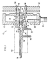
- FIG. 1 a spectroscopic plasma torch 10.
- the torch 10 is formed with a microwave housing 12 which contains a microwave cavity 14 symmetrically disposed about an aperture 16 which extends through the housing 12.
- a dielectric, microwave permeable plasma discharge tube 18 extends through the aperture 12 and has its longitudinal axis coincident with the axis of symmetry for the cavity 14.
- the housing 12 is preferably both electrically and thermally conductive and may be formed from a metal such as aluminum. Quartz, alumina, boron nitride and beryllium are all suitable materials for the plasma discharge tube 18.
- a coaxial connector 20 and microwave coupling loop antenna 22 are used to couple a microwave power source to the cavity 14.
- a torch body 24 is attached to one end 26 of the plasma discharge tube 18.
- a thermal isolation washer 25 maintains portions of the torch body 24 in spaced apart relationship from the microwave housing 12.
- the torch body 24 possesses an end bore 28 which is juxtaposed in coaxial alignment with the longitudinal axis of the plasma discharge tube 18.
- a fluid passageway 30 connects the end bore 28 with a source of plasma support gas.
- Vortex means 32 are disposed in the end bore 28 downstream from the fluid passageway 30 for inducing vortex flow in the plasma support gas moving through the discharge tube to both suspend and stabilize a plasma 34 about portions of the longitudinal axis and away from the interior surface of the discharge tube 18.
- High velocity gas jet means 36 are attached to the torch body 24 and extend beyond end 35 of the vortex means 32 as shown.
- the jet means 36 functions to introduce gaseous sample materials directly into the vortex stabilized plasma 34 thereby avoiding the formation of carbon deposits inside the plasma discharge tube 18 caused by the premature thermal pyrolysis of organic sample materials outside of the plasma.
- a fluid passageway 38 connects the gas jet means 36 to a source of gaseous sample materials such as, for example, the output from a gas chromatograph.
- the gas jet means 36 includes a hollow, elongate nozzle 40 formed of a dielectric material such as, for example, alumina, beryllia, boron nitride or quartz.
- the nozzle 40 possesses a first end 42 and a second end 44. The first end 42 of the nozzle 49 is connected to a source of jet gas through a fluid passageway 46.
- the flow rate of jet gas through the passageway 46 is selected to provide the optimum velocity for injecting sample materials into the plasma 34.
- the jet gas, the plasma support gas and the carrier gas used to transport and separate sample materials in a chromatographic column are the same type of gas.
- gas is ultrapure helium.
- Heat sink means 48 are shown in thermal communication with the other end 50 of the plasma discharge tube 18. Although such heat smk means 48 are shown in FIG. 1 as a metal cooling fin 52, it is to be understood that other means, such as, for example, a water cooled jacket (not shown) could be satisfactorily employed.
- a graphite ferrule 54 is interposed between exterior portions 56 of the plasma discharge tube 18 proximate the other end 50 and portions of the metallic cooling fin 52 to enhance thermal transfer. Threaded fasteners 58 are used to both secure the cooling fin 52 to the microwave housing 12 and compress the graphite ferrule 54 into conformance with portions of the tube 18.
- heating means which are shown schematically as element 60, may be provided.
- the heating means may, for example, comprise an infrared heat lamp (not shown), a length of electrical heater tape wrapped around the torch body (not shown), or preferably a metal housing which provides a thermal mass, adapted to receive portions of the heater body 24 and an electric cartridge heater (both not shown).
- FIG. 2A there is shown in cross-section a prior art capillary type dielectric plasma discharge tube 210 made from fused quartz.
- the tube possesses an internal bore 212 typically less than 2 mm in diameter.
- a plasma 214 may be formed in the capillary tube either through inductive coupling or induced with microwaves. Because the plasma support gas moves with laminar flow through the internal bore 212, the plasma is in direct contact with portions of the interior surface of the tube. Because of the high temperatures generated by the plasma, it is necessary to surround the capillary tube with cooling means, such as, for example, a water jacket (not shown).
- FIG. 2B is a cross-sectional view of the prior art vortex flow type plasma discharge tube 216 which is fabricated entirely from fused quartz and disclosed in the Bollo-Kamara and Codding article. It is noted that this torch was not used in conjunction with a gas chromatograph. Rather an aerosol was created and introduced into the plasma.
- a concentric tube arrangement is employed for torch construction.
- An inner quartz tube 217 possesses a pair of helical threads formed in a larger diameter end portion 218.
- a concentric outer quartz tube 219 is heat shrunk around the threaded end portion 218 of the inner quartz tube 217 to form first and second helical gas passageways 220 and 221 respectively. Special care must be taken to seal these passageways and avoid an axial gas flow between the concentric tubes.
- a seal 223 is formed around the annular gap between inner tube 217 and outer tube 219.
- a fluid passageway 222 is provided for a plasma support gas.
- a fluid passageway 224 in the inner tube 217 is used for the introduction of an analyte aerosol.
- the passageway 224 does not extend beyond the end of the double threaded end portion 218 but is co-terminus therewith at an end surface 226.
- An aerosol mixing region 228 is positioned upstream from a plasma 230. Even if scavenging gases are used, carbon deposits 232 tend to form on the inner surface of the discharge tube because organic analytes have a tendency to undergo premature thermal pyrolysis before they enter the plasma 230.
- Other prior art vortex type plasma discharge tubes are known in which the inner tube 217 has been fabricated from either brass or polytetrafluorethylene. These known prior art tubes are not believed to have employed more than two helical passageways to induce a vortex gas flow.
- FIG. 3 provides an enlarged, partially broken away phantom view of one embodiment of the vortex means 32 and the high velocity gas jet means 36 shown in somewhat less detail in FIG. 1.
- the dielectric plasma discharge tube 18 is shown with the one end 26 assembled on the torch body 24 so as to form an overlapping joint 64.
- the end bore 28 is of smaller diameter than the inside diameter of the discharge tube 18.
- the end bore 28 has an outwardly tapered transition region 66 which prevents the formation of unwanted turbulence in the tangentially flowing plasma support gas as it moves from a smaller to a larger cross-sectional area.
- Those skilled in the art will appreciate that a design in which the diameter of the end bore is larger than the inside diameter of the discharge tube 18 will give rise to some unwanted turbulence.
- a tapered transition region 66 can be avoided altogether by configuring the inside diameter of the discharge tube 18 to be the same as and contiguous with the end bore 28.
- a metal coupling 68 is used to secure the plasma discharge tube 18 to the torch body 24.
- the coupling 68 may be brazed in place to form a permanent assembly.
- the coupling 68 may function simply as a spring retention clip since a hermetic seal is not required to prevent undesirable perturbations to the plasma.
- the design of the FIG. 3 embodiment has been optimized for use with helium as the plasma support gas.
- the associated microwave cavity 14 has an axial length of 18 mm and possess a reentrant flange portion 70 as can be seen in FIG. 1.
- the reentrant flange portion 70 is 8 mm in length and possesses an annular lip 72.
- the vortex means 32 comprises a metal insert with six equally spaced helical grooves. Although selected other materials may be employed, the use of metal for the vortex insert and the torch body 24 is preferred to facilitate the maintenance of close dimensional tolerances.
- a plurality of helical plasma support gas channels 62 are formed. The arrangement of these channels is shown in FIG.
- FIG. 4 which is a cross-sectional view of the six channel vortex insert as seen through the lines 4-4 of FIG. 3.
- the individual gas channels 62a, 62b, 62c, 62d, 62e, and 62f are shown uniformly spaced about the periphery of the vortex insert.
- Developmental experiments have indicated that prior art vortex producing structures which possess only two helical gas support channels are not adequate to suspend and stabilize a helium plasma which would be suitable for use in a commercially viable analytical instrument designed to detect plasma emission spectra. For such applications, at least four helical plasma gas support channels 62 are considered necessary. Dimensional constraints limit the maximum number of helical gas channels to about 9. In the FIG.
- each of the 6 individual gas channels is disposed at a helix angle (measured from the central axis) of between 60° and 85°. These values have been determined for use with a discharge tube 18 having a 6 mm inside diameter and a helium plasma support gas flow of from 2 to 6 liters per minute. These values also contemplate additional helium flow through the high velocity gas jet means 36 of about 100 ml per minute.
- the use of the high velocity gas jet means 36 for introducing gaseous sample materials into the plasma prevents the sample from being diluted in the large flow of surrounding support gas. This increases the intensity of the resulting emission.
- the introduction of the sample from the jet means also prevents the formation of carbon deposits on the wall of the plasma tube prior to entering the plasma. The observation of carbon deposits is only a visual manifestation of a more general problem of sample deposits that accrue along the plasma tube. Materials that adsorb on the wall of the plasma tube can eventually leave and enter the plasma at a later time causing peak tailing of the chromatographic signal.
- the nozzle 40 is made from alumina and has an inside diameter of .305mm and an outside diameter of .711mm.
- the second end 44 of the nozzle 40 extends 4 mm beyond the end surface 35 of the vortex means 32.
- the linear velocity of helium gas with this nozzle is approximately 2300 cm per second. It is noted for comparative purposes that a helium flow rate of 5 liters per minute through the plasma tube 18 with a 6 mm inside diameter results in an axial plasma support gas velocity of 294 cm per second.
- the end of the vortex means 35 is displaced linearly 6 mm upstream from the lip 72 on the reentrant flange 70. This arrangement results in a 2 mm upstream displacement of the second end 44 of the nozzle 40 from the lip 72. As shown in FIG. 1, the plasma 34 is induced just downstream of the lip 72.
- FIG. 5 shows four chromatographs which demonstrate the improvement in chromatographic selectivity made possible with the high velocity gas jet means 36.
- the data was measured using a plasma torch in accordance with the FIG. 3 embodiment described above.
- Curve 80a is the chromatogram from the carbon channel of an analytical instrument for a mixture of three normal homologous alkanes: C14H30; C15H32; and C16H34 without the use of the high velocity gas jet means 36.
- curve 80b is the chromatogram from the carbon channel of an analytical instrument for the same mixture of three normal homologous alkanes in which the plasma torch 10 is operated with the high velocity gas jet means 36.
- Peak 81a is associated with the organic sample solvent but is severely attenuated because the solvent extinguished the plasma.
- Peaks 82a, 83a and 84a are associated respectively with the C14, C15, and C16 alkanes.
- An area 85 under the three peaks indicates peak tailing from residual carbon deposits on the wall of the plasma discharge tube.
- the gas jet means 36 is used in a detector the same mixture of alkanes, the solvent appears as a peak 81b and does not extinguish the plasma. Moreover, there is no residual carbon tailing.
- Peaks 82b, 83b and 84b again correspond respectively to the C14, C15, and C16 alkanes. The high selectivity and absence of peak tailings provides graphic evidence of the improvements brought about by the invention.
- the curve 86,86a is the chromatograph from the phosphorus channel for tributylphosphate without the benefit of the high velocity gas jet means.
- a region 88 represents peak tailing and arises from the adsorption of phosphorus on the wall of the plasma discharge tube after the phosphorus sample has passed through the chromatographic column.
- the gas jet means 36 When the gas jet means 36 is employed, no peak tailing appears beneath 86b because all of the phosphorus enters the plasma leaving no residual to be adsorbed on the wall of the plasma tube.
- FIG. 6 is a schematic diagram of such a plasma emission detector for gas chromatography which employs the spectroscopic plasma torch of the invention.
- a complete analytical instrument 100 includes a gas chromatograph 102 which possesses an injection port 104 and a separation column 106.
- a tank of high purity helium gas 108 is connected to a gas flow controller 110 used to supply the carrier gas to the separation column 106.
- Another gas flow controller 112 regulates the plasma support gas to the torch 10.
- Still another gas flow controller 114 regulates the flow to the high velocity gas jet means.
- a microwave power source 116 is coupled to the torch 10.
- the analytical instrument 100 includes instrument support electronics 118 and optical spectrometer means 120.
- a pair of coupling mirrors 122 gather and focus the light from the plasma torch 10. That light is directed through an entrance slit 124 onto a holographic grating 126.
- a plurality of photodiode detectors 128 are disposed to detect selected spectral emissions from selected to-be-detected atomic species.
- a corresponding plurality of electrometers 130 are connected respectively to the plurality of diode detectors 128.
- Output from each electrometer is sampled 22 times a second and converted to a digital signal by an analog to digital convertor 132.
- Signals from an instrument monitoring sensor means 134 are also digitized at a similar sampling rate.
- Monitoring means 134 monitors temperatures, pressures, currents, voltages of various power supplies, interlock conditions and diagnostics.
- a central processing unit 136 communicates bi-directionally with the analog to digital converter 132, an instrument control means 138, and a general purpose instrument bus 140.
- the control means 138 functions to control various temperatures, gas solenoids, valves, plasma igniter and the power supply.
- the general purpose instrument bus 140 provides a bi-directional communication path to a workstation 142.
Landscapes
- Physics & Mathematics (AREA)
- Engineering & Computer Science (AREA)
- Plasma & Fusion (AREA)
- Electromagnetism (AREA)
- Spectroscopy & Molecular Physics (AREA)
- Investigating, Analyzing Materials By Fluorescence Or Luminescence (AREA)
- Other Investigation Or Analysis Of Materials By Electrical Means (AREA)
- Plasma Technology (AREA)
Applications Claiming Priority (2)
| Application Number | Priority Date | Filing Date | Title |
|---|---|---|---|
| US07/349,205 US5083004A (en) | 1989-05-09 | 1989-05-09 | Spectroscopic plasma torch for microwave induced plasmas |
| US349205 | 1999-07-07 |
Publications (3)
| Publication Number | Publication Date |
|---|---|
| EP0397468A2 true EP0397468A2 (de) | 1990-11-14 |
| EP0397468A3 EP0397468A3 (de) | 1991-09-25 |
| EP0397468B1 EP0397468B1 (de) | 1996-03-27 |
Family
ID=23371338
Family Applications (1)
| Application Number | Title | Priority Date | Filing Date |
|---|---|---|---|
| EP90304988A Expired - Lifetime EP0397468B1 (de) | 1989-05-09 | 1990-05-09 | Spektroskopischer Plasmabrenner für Mikrowellenplasma |
Country Status (5)
| Country | Link |
|---|---|
| US (1) | US5083004A (de) |
| EP (1) | EP0397468B1 (de) |
| JP (1) | JPH02309599A (de) |
| CA (1) | CA2016273A1 (de) |
| DE (1) | DE69026136T2 (de) |
Cited By (14)
| Publication number | Priority date | Publication date | Assignee | Title |
|---|---|---|---|---|
| WO1997013141A1 (en) * | 1995-10-06 | 1997-04-10 | Massachusetts Institute Of Technology | Microwave plasma monitoring system for the elemental composition analysis of high temperature process streams |
| EP0792091A1 (de) * | 1995-12-27 | 1997-08-27 | Nippon Telegraph And Telephone Corporation | Verfahren und Vorrichtung zur elementaren Analyse |
| FR2773300A1 (fr) * | 1997-12-29 | 1999-07-02 | Air Liquide | Torche a plasma et installation d'analyse de gaz utilisant une telle torche |
| EP0930810A1 (de) * | 1997-12-29 | 1999-07-21 | L'air Liquide, Societe Anonyme Pour L'etude Et L'exploitation Des Procedes Georges Claude | Plasmabrenner mit Verstellbarer Verteilung und Gasanalysenanlage die diesen Brenner gebraucht |
| US6081329A (en) * | 1995-11-03 | 2000-06-27 | Cohn; Daniel R. | Compact trace element sensor which utilizes microwave generated plasma and which is portable by an individual |
| WO2003098980A1 (en) * | 2002-05-21 | 2003-11-27 | Varian Australia Pty Ltd | Plasma torch for microwave induced plasmas |
| WO2006037991A3 (en) * | 2004-10-04 | 2006-06-08 | C Tech Innovation Ltd | Microwave plasma apparatus with vorticular gas flow |
| WO2006014862A3 (en) * | 2004-07-30 | 2007-01-18 | Amarante Technologies Inc | Plasma nozzle array for providing uniform scalable microwave plasma generation |
| WO2006014455A3 (en) * | 2004-07-07 | 2007-01-18 | Amarante Technologies Inc | Microwave plasma nozzle with enhanced plume stability and heating efficiency |
| US7921804B2 (en) | 2008-12-08 | 2011-04-12 | Amarante Technologies, Inc. | Plasma generating nozzle having impedance control mechanism |
| US7976672B2 (en) | 2006-02-17 | 2011-07-12 | Saian Corporation | Plasma generation apparatus and work processing apparatus |
| ES2402609R1 (es) * | 2010-11-04 | 2013-05-09 | Univ Cordoba | Dispositivo, sistema y metodo de introduccion de muestras gaseosas en plasmas contenidos en tubos dielectricos |
| CN110677973A (zh) * | 2019-11-07 | 2020-01-10 | 成都悦坤科技有限公司 | 微波等离子体废固裂解装置 |
| CN112996209A (zh) * | 2021-05-07 | 2021-06-18 | 四川大学 | 一种微波激发常压等离子体射流的结构和阵列结构 |
Families Citing this family (31)
| Publication number | Priority date | Publication date | Assignee | Title |
|---|---|---|---|---|
| US5212365A (en) * | 1991-12-27 | 1993-05-18 | Cetac Technologies, Inc. | Direct injection micro nebulizer system and method of use |
| US5349154A (en) * | 1991-10-16 | 1994-09-20 | Rockwell International Corporation | Diamond growth by microwave generated plasma flame |
| JP2594579Y2 (ja) * | 1991-11-25 | 1999-04-26 | 日本分光株式会社 | 分光光度計 |
| US5793013A (en) * | 1995-06-07 | 1998-08-11 | Physical Sciences, Inc. | Microwave-driven plasma spraying apparatus and method for spraying |
| US6218640B1 (en) * | 1999-07-19 | 2001-04-17 | Timedomain Cvd, Inc. | Atmospheric pressure inductive plasma apparatus |
| JP2000133494A (ja) | 1998-10-23 | 2000-05-12 | Mitsubishi Heavy Ind Ltd | マイクロ波プラズマ発生装置及び方法 |
| KR19990068381A (ko) * | 1999-05-11 | 1999-09-06 | 허방욱 | 마이크로웨이브플라즈마버너 |
| US6696662B2 (en) | 2000-05-25 | 2004-02-24 | Advanced Energy Industries, Inc. | Methods and apparatus for plasma processing |
| DE10112494C2 (de) * | 2001-03-15 | 2003-12-11 | Mtu Aero Engines Gmbh | Verfahren zum Plasmaschweißen |
| JP4232951B2 (ja) * | 2002-11-07 | 2009-03-04 | 独立行政法人産業技術総合研究所 | 誘導結合プラズマトーチ |
| US20060052883A1 (en) * | 2004-09-08 | 2006-03-09 | Lee Sang H | System and method for optimizing data acquisition of plasma using a feedback control module |
| SE528705C2 (sv) * | 2004-10-22 | 2007-01-30 | Sandvik Intellectual Property | Förfarande jämte anordning för att tända och övervaka en brännare |
| DE102006037995B4 (de) * | 2006-08-14 | 2009-11-12 | Bundesanstalt für Materialforschung und -Prüfung (BAM) | Analyseverfahren für Festkörperproben und Vorrichtung zur Durchführung desselben |
| US8063337B1 (en) * | 2007-03-23 | 2011-11-22 | Elemental Scientific, Inc. | Mass spectrometry injection system and apparatus |
| US20100074810A1 (en) * | 2008-09-23 | 2010-03-25 | Sang Hun Lee | Plasma generating system having tunable plasma nozzle |
| US20100201272A1 (en) * | 2009-02-09 | 2010-08-12 | Sang Hun Lee | Plasma generating system having nozzle with electrical biasing |
| US20100254853A1 (en) * | 2009-04-06 | 2010-10-07 | Sang Hun Lee | Method of sterilization using plasma generated sterilant gas |
| CN203244808U (zh) * | 2010-02-26 | 2013-10-23 | 珀金埃尔默健康科技有限公司 | 喷射组件、喷射组件插入件、火焰检测器以及包括其的套件 |
| WO2012153332A2 (en) | 2011-05-09 | 2012-11-15 | Ionmed Ltd | Tissue welding using plasma |
| US10477665B2 (en) * | 2012-04-13 | 2019-11-12 | Amastan Technologies Inc. | Microwave plasma torch generating laminar flow for materials processing |
| US9516735B2 (en) | 2012-07-13 | 2016-12-06 | Perkinelmer Health Sciences, Inc. | Torches and methods of using them |
| US10993309B2 (en) * | 2012-07-13 | 2021-04-27 | Perkinelmer Health Sciences, Inc. | Torches and methods of using them |
| US9259798B2 (en) * | 2012-07-13 | 2016-02-16 | Perkinelmer Health Sciences, Inc. | Torches and methods of using them |
| US9310308B2 (en) | 2012-12-07 | 2016-04-12 | Ldetek Inc. | Micro-plasma emission detector unit and method |
| CN104233191A (zh) * | 2013-06-08 | 2014-12-24 | 北京北方微电子基地设备工艺研究中心有限责任公司 | 加热腔室及等离子体加工设备 |
| US20160135277A1 (en) * | 2014-11-11 | 2016-05-12 | Agilent Technologies, Inc. | Reduction of ambient gas entrainment and ion current noise in plasma based spectrometry |
| US10126278B2 (en) | 2016-03-04 | 2018-11-13 | Ldetek Inc. | Thermal stress resistant micro-plasma emission detector unit |
| US10834807B1 (en) * | 2016-04-01 | 2020-11-10 | Elemental Scientific, Inc. | ICP torch assembly with retractable injector |
| WO2019144228A1 (en) | 2018-01-23 | 2019-08-01 | Ldetek Inc. | Valve assembly for a gas chromatograph |
| US11602039B2 (en) | 2018-12-20 | 2023-03-07 | Mécanique Analytique Inc | Electrode assemblies for plasma discharge devices |
| US20250275050A1 (en) * | 2022-04-22 | 2025-08-28 | Standard Biotools Canada Inc. | Sealed Plasma Torch |
Family Cites Families (19)
| Publication number | Priority date | Publication date | Assignee | Title |
|---|---|---|---|---|
| USRE29304E (en) * | 1963-10-21 | 1977-07-12 | Raydne Limited | Plasma light source for spectroscopic investigation |
| US3450926A (en) * | 1966-10-10 | 1969-06-17 | Air Reduction | Plasma torch |
| US3562486A (en) * | 1969-05-29 | 1971-02-09 | Thermal Dynamics Corp | Electric arc torches |
| US3892882A (en) * | 1973-05-25 | 1975-07-01 | Union Carbide Corp | Process for plasma flame spray coating in a sub-atmospheric pressure environment |
| JPS5544904B2 (de) * | 1973-09-05 | 1980-11-14 | ||
| US4060708A (en) * | 1975-09-17 | 1977-11-29 | Wisconsin Alumni Research Foundation | Metastable argon stabilized arc devices for spectroscopic analysis |
| DE2716592C3 (de) * | 1976-04-15 | 1979-11-08 | Hitachi, Ltd., Tokio | Plasma-Ätzvorrichtung |
| US4225235A (en) * | 1978-07-10 | 1980-09-30 | Beckman Instruments, Inc. | Sample introduction system for flameless emission spectroscopy |
| JPS5546266A (en) * | 1978-09-28 | 1980-03-31 | Daido Steel Co Ltd | Plasma torch |
| FR2480552A1 (fr) * | 1980-04-10 | 1981-10-16 | Anvar | Generateur de plasma |
| US4482246A (en) * | 1982-09-20 | 1984-11-13 | Meyer Gerhard A | Inductively coupled plasma discharge in flowing non-argon gas at atmospheric pressure for spectrochemical analysis |
| USH100H (en) * | 1982-11-30 | 1986-08-05 | The United States Of America As Represented By The Secretary Of The Navy | Apparatus for nebulizing particulate laden samples of lubricating oils |
| DE3310742A1 (de) * | 1983-03-24 | 1984-09-27 | Siemens AG, 1000 Berlin und 8000 München | Plasmabrenner fuer die icp-emissionsspektrometrie |
| US4654504A (en) * | 1983-11-30 | 1987-03-31 | Hewlett-Packard Company | Water-cooled gas discharge detector |
| US4659899A (en) * | 1984-10-24 | 1987-04-21 | The Perkin-Elmer Corporation | Vacuum-compatible air-cooled plasma device |
| US4586368A (en) * | 1985-04-05 | 1986-05-06 | The United States Of America As Represented By The United States Department Of Energy | Atmospheric pressure helium afterglow discharge detector for gas chromatography |
| US4833294A (en) * | 1986-08-29 | 1989-05-23 | Research Corporation | Inductively coupled helium plasma torch |
| US4766287A (en) * | 1987-03-06 | 1988-08-23 | The Perkin-Elmer Corporation | Inductively coupled plasma torch with adjustable sample injector |
| JPH01129141A (ja) * | 1987-11-16 | 1989-05-22 | Shimadzu Corp | Icp発光分析装置 |
-
1989
- 1989-05-09 US US07/349,205 patent/US5083004A/en not_active Expired - Fee Related
-
1990
- 1990-05-08 CA CA002016273A patent/CA2016273A1/en not_active Abandoned
- 1990-05-09 DE DE69026136T patent/DE69026136T2/de not_active Expired - Fee Related
- 1990-05-09 JP JP2117793A patent/JPH02309599A/ja active Pending
- 1990-05-09 EP EP90304988A patent/EP0397468B1/de not_active Expired - Lifetime
Cited By (22)
| Publication number | Priority date | Publication date | Assignee | Title |
|---|---|---|---|---|
| US5671045A (en) * | 1993-10-22 | 1997-09-23 | Masachusetts Institute Of Technology | Microwave plasma monitoring system for the elemental composition analysis of high temperature process streams |
| WO1997013141A1 (en) * | 1995-10-06 | 1997-04-10 | Massachusetts Institute Of Technology | Microwave plasma monitoring system for the elemental composition analysis of high temperature process streams |
| US6081329A (en) * | 1995-11-03 | 2000-06-27 | Cohn; Daniel R. | Compact trace element sensor which utilizes microwave generated plasma and which is portable by an individual |
| EP0792091A1 (de) * | 1995-12-27 | 1997-08-27 | Nippon Telegraph And Telephone Corporation | Verfahren und Vorrichtung zur elementaren Analyse |
| US5818581A (en) * | 1995-12-27 | 1998-10-06 | Nippon Telegraph And Telephone Corporation | Elemental analysis method and apparatus |
| FR2773300A1 (fr) * | 1997-12-29 | 1999-07-02 | Air Liquide | Torche a plasma et installation d'analyse de gaz utilisant une telle torche |
| EP0930810A1 (de) * | 1997-12-29 | 1999-07-21 | L'air Liquide, Societe Anonyme Pour L'etude Et L'exploitation Des Procedes Georges Claude | Plasmabrenner mit Verstellbarer Verteilung und Gasanalysenanlage die diesen Brenner gebraucht |
| US6236012B1 (en) | 1997-12-29 | 2001-05-22 | L'air Liquide, Societe Anonyme Pour L'etude Et L'exploitation Des Procedes Georges Claude | Plasma torch with an adjustable injector and gas analyzer using such a torch |
| WO2003098980A1 (en) * | 2002-05-21 | 2003-11-27 | Varian Australia Pty Ltd | Plasma torch for microwave induced plasmas |
| KR100946434B1 (ko) * | 2004-07-07 | 2010-03-10 | 아마란테 테크놀러지스 인코포레이티드 | 플룸 안전성과 가열 효율이 향상된 마이크로파 플라즈마 노즐, 플라즈마 생성시스템 및 플라즈마 생성방법 |
| WO2006014455A3 (en) * | 2004-07-07 | 2007-01-18 | Amarante Technologies Inc | Microwave plasma nozzle with enhanced plume stability and heating efficiency |
| AU2005270006B2 (en) * | 2004-07-07 | 2009-01-08 | Amarante Technologies, Inc. | Microwave plasma nozzle with enhanced plume stability and heating efficiency |
| RU2355137C2 (ru) * | 2004-07-07 | 2009-05-10 | Амарант Текнолоджиз, Инк. | Сопло микроволнового плазматрона с повышенной стабильностью факела и эффективностью нагрева |
| KR100906836B1 (ko) * | 2004-07-07 | 2009-07-08 | 아마란테 테크놀러지스 인코포레이티드 | 플룸 안전성과 가열 효율이 향상된 마이크로파 플라즈마 노즐, 플라즈마 생성시스템 및 플라즈마 생성방법 |
| US8035057B2 (en) | 2004-07-07 | 2011-10-11 | Amarante Technologies, Inc. | Microwave plasma nozzle with enhanced plume stability and heating efficiency |
| WO2006014862A3 (en) * | 2004-07-30 | 2007-01-18 | Amarante Technologies Inc | Plasma nozzle array for providing uniform scalable microwave plasma generation |
| WO2006037991A3 (en) * | 2004-10-04 | 2006-06-08 | C Tech Innovation Ltd | Microwave plasma apparatus with vorticular gas flow |
| US7976672B2 (en) | 2006-02-17 | 2011-07-12 | Saian Corporation | Plasma generation apparatus and work processing apparatus |
| US7921804B2 (en) | 2008-12-08 | 2011-04-12 | Amarante Technologies, Inc. | Plasma generating nozzle having impedance control mechanism |
| ES2402609R1 (es) * | 2010-11-04 | 2013-05-09 | Univ Cordoba | Dispositivo, sistema y metodo de introduccion de muestras gaseosas en plasmas contenidos en tubos dielectricos |
| CN110677973A (zh) * | 2019-11-07 | 2020-01-10 | 成都悦坤科技有限公司 | 微波等离子体废固裂解装置 |
| CN112996209A (zh) * | 2021-05-07 | 2021-06-18 | 四川大学 | 一种微波激发常压等离子体射流的结构和阵列结构 |
Also Published As
| Publication number | Publication date |
|---|---|
| DE69026136D1 (de) | 1996-05-02 |
| EP0397468B1 (de) | 1996-03-27 |
| CA2016273A1 (en) | 1990-11-09 |
| EP0397468A3 (de) | 1991-09-25 |
| DE69026136T2 (de) | 1996-11-28 |
| JPH02309599A (ja) | 1990-12-25 |
| US5083004A (en) | 1992-01-21 |
Similar Documents
| Publication | Publication Date | Title |
|---|---|---|
| EP0397468B1 (de) | Spektroskopischer Plasmabrenner für Mikrowellenplasma | |
| Jankowski et al. | Microwave induced plasma analytical spectrometry | |
| US9847217B2 (en) | Devices and systems including a boost device | |
| US8622735B2 (en) | Boost devices and methods of using them | |
| Quimby et al. | Evaluation of a microwave cavity, discharge tube, and gas flow system for combined gas chromatography-atomic emission detection | |
| US4413185A (en) | Selective photoionization gas chromatograph detector | |
| US4794230A (en) | Low-pressure water-cooled inductively coupled plasma torch | |
| CA3208773A1 (en) | Inductively coupled plasma torches and methods and systems including same | |
| EP1279955B2 (de) | Heliumionisierungsdetektor | |
| CA2608528C (en) | Boost devices and methods of using them | |
| Story et al. | Reduced-pressure microwave-induced plasma mass spectrometric detection of phosphorus and sulphur in gas chromatographic eluates | |
| EP2543995B1 (de) | Heliumionisierungsdetektor | |
| JP2001512617A (ja) | 元素選択検出法、その方法を使用するマイクロプラズマ質量分析計、マイクロプラズマイオン源、及びそれらの応用 | |
| Mason et al. | Helium microwave induced plasma atomic emission detection for liquid chromatography utilizing a moving band interface | |
| JPH10197485A (ja) | 電子捕獲型検出器 | |
| KR100453293B1 (ko) | 속빈 음극관을 가지는 분광분석시스템의 글로우 방전셀 | |
| Hernandez et al. | A desolvation unit for introducing microliter volumes of a dry aerosol to an atomic spectrometric system |
Legal Events
| Date | Code | Title | Description |
|---|---|---|---|
| PUAI | Public reference made under article 153(3) epc to a published international application that has entered the european phase |
Free format text: ORIGINAL CODE: 0009012 |
|
| AK | Designated contracting states |
Kind code of ref document: A2 Designated state(s): CH DE FR GB IT LI |
|
| 17P | Request for examination filed |
Effective date: 19901227 |
|
| PUAL | Search report despatched |
Free format text: ORIGINAL CODE: 0009013 |
|
| AK | Designated contracting states |
Kind code of ref document: A3 Designated state(s): CH DE FR GB IT LI |
|
| 17Q | First examination report despatched |
Effective date: 19930525 |
|
| GRAA | (expected) grant |
Free format text: ORIGINAL CODE: 0009210 |
|
| AK | Designated contracting states |
Kind code of ref document: B1 Designated state(s): CH DE FR GB IT LI |
|
| REG | Reference to a national code |
Ref country code: CH Ref legal event code: NV Representative=s name: BOVARD AG PATENTANWAELTE |
|
| ITF | It: translation for a ep patent filed | ||
| REF | Corresponds to: |
Ref document number: 69026136 Country of ref document: DE Date of ref document: 19960502 |
|
| ET | Fr: translation filed | ||
| PLBE | No opposition filed within time limit |
Free format text: ORIGINAL CODE: 0009261 |
|
| STAA | Information on the status of an ep patent application or granted ep patent |
Free format text: STATUS: NO OPPOSITION FILED WITHIN TIME LIMIT |
|
| 26N | No opposition filed | ||
| PGFP | Annual fee paid to national office [announced via postgrant information from national office to epo] |
Ref country code: FR Payment date: 19980420 Year of fee payment: 9 |
|
| PGFP | Annual fee paid to national office [announced via postgrant information from national office to epo] |
Ref country code: DE Payment date: 19980421 Year of fee payment: 9 |
|
| PGFP | Annual fee paid to national office [announced via postgrant information from national office to epo] |
Ref country code: GB Payment date: 19980427 Year of fee payment: 9 |
|
| PGFP | Annual fee paid to national office [announced via postgrant information from national office to epo] |
Ref country code: CH Payment date: 19980505 Year of fee payment: 9 |
|
| PG25 | Lapsed in a contracting state [announced via postgrant information from national office to epo] |
Ref country code: GB Free format text: LAPSE BECAUSE OF NON-PAYMENT OF DUE FEES Effective date: 19990509 |
|
| PG25 | Lapsed in a contracting state [announced via postgrant information from national office to epo] |
Ref country code: LI Free format text: LAPSE BECAUSE OF NON-PAYMENT OF DUE FEES Effective date: 19990531 Ref country code: CH Free format text: LAPSE BECAUSE OF NON-PAYMENT OF DUE FEES Effective date: 19990531 |
|
| GBPC | Gb: european patent ceased through non-payment of renewal fee |
Effective date: 19990509 |
|
| REG | Reference to a national code |
Ref country code: CH Ref legal event code: PL |
|
| PG25 | Lapsed in a contracting state [announced via postgrant information from national office to epo] |
Ref country code: FR Free format text: LAPSE BECAUSE OF NON-PAYMENT OF DUE FEES Effective date: 20000131 |
|
| PG25 | Lapsed in a contracting state [announced via postgrant information from national office to epo] |
Ref country code: DE Free format text: LAPSE BECAUSE OF NON-PAYMENT OF DUE FEES Effective date: 20000301 |
|
| REG | Reference to a national code |
Ref country code: FR Ref legal event code: ST |
|
| REG | Reference to a national code |
Ref country code: FR Ref legal event code: TP |
|
| PG25 | Lapsed in a contracting state [announced via postgrant information from national office to epo] |
Ref country code: IT Free format text: LAPSE BECAUSE OF NON-PAYMENT OF DUE FEES;WARNING: LAPSES OF ITALIAN PATENTS WITH EFFECTIVE DATE BEFORE 2007 MAY HAVE OCCURRED AT ANY TIME BEFORE 2007. THE CORRECT EFFECTIVE DATE MAY BE DIFFERENT FROM THE ONE RECORDED. Effective date: 20050509 |