EP0930810A1 - Plasmabrenner mit Verstellbarer Verteilung und Gasanalysenanlage die diesen Brenner gebraucht - Google Patents
Plasmabrenner mit Verstellbarer Verteilung und Gasanalysenanlage die diesen Brenner gebraucht Download PDFInfo
- Publication number
- EP0930810A1 EP0930810A1 EP98402992A EP98402992A EP0930810A1 EP 0930810 A1 EP0930810 A1 EP 0930810A1 EP 98402992 A EP98402992 A EP 98402992A EP 98402992 A EP98402992 A EP 98402992A EP 0930810 A1 EP0930810 A1 EP 0930810A1
- Authority
- EP
- European Patent Office
- Prior art keywords
- gas
- plasma
- tube
- injector
- torch
- Prior art date
- Legal status (The legal status is an assumption and is not a legal conclusion. Google has not performed a legal analysis and makes no representation as to the accuracy of the status listed.)
- Withdrawn
Links
- 238000004868 gas analysis Methods 0.000 title claims description 7
- 239000007789 gas Substances 0.000 claims abstract description 137
- XKRFYHLGVUSROY-UHFFFAOYSA-N Argon Chemical compound [Ar] XKRFYHLGVUSROY-UHFFFAOYSA-N 0.000 claims abstract description 32
- 239000012535 impurity Substances 0.000 claims abstract description 21
- 238000004458 analytical method Methods 0.000 claims abstract description 19
- 229910052786 argon Inorganic materials 0.000 claims abstract description 16
- 239000002245 particle Substances 0.000 claims description 21
- 238000009434 installation Methods 0.000 claims description 13
- 239000007787 solid Substances 0.000 claims description 8
- 238000012545 processing Methods 0.000 claims description 7
- 238000004807 desolvation Methods 0.000 claims description 6
- 150000001875 compounds Chemical class 0.000 claims description 5
- 238000004519 manufacturing process Methods 0.000 claims description 5
- 238000002663 nebulization Methods 0.000 claims description 5
- 230000005284 excitation Effects 0.000 claims description 4
- 239000001307 helium Substances 0.000 claims description 4
- 229910052734 helium Inorganic materials 0.000 claims description 4
- SWQJXJOGLNCZEY-UHFFFAOYSA-N helium atom Chemical compound [He] SWQJXJOGLNCZEY-UHFFFAOYSA-N 0.000 claims description 4
- 239000003039 volatile agent Substances 0.000 claims description 4
- 238000001514 detection method Methods 0.000 claims description 3
- 230000003287 optical effect Effects 0.000 claims description 3
- 230000001681 protective effect Effects 0.000 claims description 2
- 239000012266 salt solution Substances 0.000 claims description 2
- 230000000694 effects Effects 0.000 abstract description 5
- 230000005855 radiation Effects 0.000 abstract description 2
- 238000004033 diameter control Methods 0.000 abstract 1
- 235000010599 Verbascum thapsus Nutrition 0.000 description 57
- 244000178289 Verbascum thapsus Species 0.000 description 13
- 238000000034 method Methods 0.000 description 13
- 238000002347 injection Methods 0.000 description 12
- 239000007924 injection Substances 0.000 description 12
- 239000000243 solution Substances 0.000 description 5
- 238000004804 winding Methods 0.000 description 5
- 239000000443 aerosol Substances 0.000 description 4
- 238000005259 measurement Methods 0.000 description 4
- 239000000203 mixture Substances 0.000 description 4
- 230000009471 action Effects 0.000 description 3
- 238000004364 calculation method Methods 0.000 description 3
- 230000005672 electromagnetic field Effects 0.000 description 3
- 238000001914 filtration Methods 0.000 description 3
- 230000006870 function Effects 0.000 description 3
- QGZKDVFQNNGYKY-UHFFFAOYSA-N Ammonia Chemical compound N QGZKDVFQNNGYKY-UHFFFAOYSA-N 0.000 description 2
- IJGRMHOSHXDMSA-UHFFFAOYSA-N Atomic nitrogen Chemical compound N#N IJGRMHOSHXDMSA-UHFFFAOYSA-N 0.000 description 2
- XEEYBQQBJWHFJM-UHFFFAOYSA-N Iron Chemical compound [Fe] XEEYBQQBJWHFJM-UHFFFAOYSA-N 0.000 description 2
- PXHVJJICTQNCMI-UHFFFAOYSA-N Nickel Chemical compound [Ni] PXHVJJICTQNCMI-UHFFFAOYSA-N 0.000 description 2
- BLRPTPMANUNPDV-UHFFFAOYSA-N Silane Chemical compound [SiH4] BLRPTPMANUNPDV-UHFFFAOYSA-N 0.000 description 2
- 239000013626 chemical specie Substances 0.000 description 2
- 239000011261 inert gas Substances 0.000 description 2
- 239000007788 liquid Substances 0.000 description 2
- 229910052751 metal Inorganic materials 0.000 description 2
- 150000003839 salts Chemical class 0.000 description 2
- 239000004065 semiconductor Substances 0.000 description 2
- 229910000077 silane Inorganic materials 0.000 description 2
- 229910052710 silicon Inorganic materials 0.000 description 2
- 239000010703 silicon Substances 0.000 description 2
- 239000002904 solvent Substances 0.000 description 2
- 241000894007 species Species 0.000 description 2
- XLYOFNOQVPJJNP-UHFFFAOYSA-N water Chemical compound O XLYOFNOQVPJJNP-UHFFFAOYSA-N 0.000 description 2
- ZAMOUSCENKQFHK-UHFFFAOYSA-N Chlorine atom Chemical compound [Cl] ZAMOUSCENKQFHK-UHFFFAOYSA-N 0.000 description 1
- PWHULOQIROXLJO-UHFFFAOYSA-N Manganese Chemical compound [Mn] PWHULOQIROXLJO-UHFFFAOYSA-N 0.000 description 1
- VYPSYNLAJGMNEJ-UHFFFAOYSA-N Silicium dioxide Chemical compound O=[Si]=O VYPSYNLAJGMNEJ-UHFFFAOYSA-N 0.000 description 1
- 241001080024 Telles Species 0.000 description 1
- 230000001133 acceleration Effects 0.000 description 1
- 239000002253 acid Substances 0.000 description 1
- 238000007792 addition Methods 0.000 description 1
- 229910021529 ammonia Inorganic materials 0.000 description 1
- 238000012550 audit Methods 0.000 description 1
- 238000007664 blowing Methods 0.000 description 1
- 230000005587 bubbling Effects 0.000 description 1
- 238000001311 chemical methods and process Methods 0.000 description 1
- 239000000460 chlorine Substances 0.000 description 1
- 229910052801 chlorine Inorganic materials 0.000 description 1
- 238000009833 condensation Methods 0.000 description 1
- 230000005494 condensation Effects 0.000 description 1
- 238000011109 contamination Methods 0.000 description 1
- 238000000354 decomposition reaction Methods 0.000 description 1
- 230000003247 decreasing effect Effects 0.000 description 1
- 230000008021 deposition Effects 0.000 description 1
- 238000011161 development Methods 0.000 description 1
- 238000004993 emission spectroscopy Methods 0.000 description 1
- 230000008020 evaporation Effects 0.000 description 1
- 238000001704 evaporation Methods 0.000 description 1
- 238000002474 experimental method Methods 0.000 description 1
- 238000000605 extraction Methods 0.000 description 1
- 238000013213 extrapolation Methods 0.000 description 1
- 229910052736 halogen Inorganic materials 0.000 description 1
- 150000002367 halogens Chemical class 0.000 description 1
- 238000010438 heat treatment Methods 0.000 description 1
- 230000007062 hydrolysis Effects 0.000 description 1
- 238000006460 hydrolysis reaction Methods 0.000 description 1
- 230000006698 induction Effects 0.000 description 1
- 230000002452 interceptive effect Effects 0.000 description 1
- 229910052742 iron Inorganic materials 0.000 description 1
- 229910052748 manganese Inorganic materials 0.000 description 1
- 239000011572 manganese Substances 0.000 description 1
- 239000000463 material Substances 0.000 description 1
- 230000007246 mechanism Effects 0.000 description 1
- 239000012528 membrane Substances 0.000 description 1
- 239000002923 metal particle Substances 0.000 description 1
- 230000004048 modification Effects 0.000 description 1
- 238000012986 modification Methods 0.000 description 1
- 230000007935 neutral effect Effects 0.000 description 1
- 229910052759 nickel Inorganic materials 0.000 description 1
- 229910052757 nitrogen Inorganic materials 0.000 description 1
- 230000002093 peripheral effect Effects 0.000 description 1
- 238000004611 spectroscopical analysis Methods 0.000 description 1
- 239000000126 substance Substances 0.000 description 1
- 238000012546 transfer Methods 0.000 description 1
- 230000032258 transport Effects 0.000 description 1
- 238000011144 upstream manufacturing Methods 0.000 description 1
Images


Classifications
-
- H—ELECTRICITY
- H05—ELECTRIC TECHNIQUES NOT OTHERWISE PROVIDED FOR
- H05H—PLASMA TECHNIQUE; PRODUCTION OF ACCELERATED ELECTRICALLY-CHARGED PARTICLES OR OF NEUTRONS; PRODUCTION OR ACCELERATION OF NEUTRAL MOLECULAR OR ATOMIC BEAMS
- H05H1/00—Generating plasma; Handling plasma
- H05H1/24—Generating plasma
- H05H1/26—Plasma torches
- H05H1/30—Plasma torches using applied electromagnetic fields, e.g. high frequency or microwave energy
Definitions
- the present invention relates to a torch with plasma, intended for the excitation of a gas with a view to its analysis.
- the invention also relates to an installation analysis of a gas using such a plasma torch.
- gas analysis techniques are indirect techniques, such as filtration, hydrolysis or bubbling, according to which the impurities with which it is to determine the concentration are extracted from the gas before analysis.
- the technique of analysis by filtration uses a gas filtration membrane to analyze in order to retain the impurities it contains. These the latter are then dissolved in an acid solution, then analyzed, for example by spectrometry, with a view to determine the nature and concentration.
- a gas sample to be analyzed is introduced into a thermal source, such as a plasma, capable of dissociating chemical species into free atoms present in the sample and then to excite and possibly to ionize the atoms obtained. These atoms excited are then detected from the measurement of different wavelengths they emit, or, if they are ionized, from the measurement of their mass.
- a thermal source such as a plasma
- the gas passing through this zone device experiences less excitation, which contributes to degrade the accuracy of the measurement.
- the object of the invention is to overcome the drawbacks cited above.
- a plasma torch for the excitation of a gas for analysis comprising an injector configured as a main tube intended to be connected to a gas supply source at analyze, and an external cylindrical double-walled sleeve, coaxial with the injector, and delimiting between its walls consecutive internal and external annular canal cylindrical supply of a plasma gas intended for be connected to a corresponding power source in view of the production of a plasma at the outlet of said sleeve, is characterized in that said injector is of diameter variable.
- the invention also relates to an installation gas analysis, characterized in that it comprises a plasma torch as defined above, connected to a gas supply source to be analyzed, to a source supply of plasma gas and advantageously also to a source of gas to guide the gas to be analyzed in the plasma generated at the outlet of the torch in the gas plasma, and optical detection means capable of measure the light intensity emitted by impurities present in the plasma, connected to a processing unit comprising means for calculating the concentration of impurities from the light intensity value measured and at least one predetermined reference value, stored in a memory associated with said unit of treatment, and obtained by prior calibration.
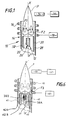
- a plasma torch is shown intended to dissociate the chemical species from a gas including impurities, to generate free atoms and excite the atoms thus obtained for the purpose of determining of the impurity concentration.
- the gas to be analyzed consists of a gas used in the field of semiconductor manufacturing, such as halogen or fluorinated gas, and the impurities are formed by metallic elements such than nickel, iron, manganese ...
- the plasma torch designated by the general numerical reference 10 includes: a central injector 12 configured in the form of a tube, a external cylindrical sleeve 14 with double wall (28/30) and a winding 16 connected to a high current source frequency 18.
- the wall 20 of the injector internally defines a channel 26 intended to be connected to a power source torch 10 into a gas to be analyzed (not shown in this figure).
- the sleeve 14 has an inner wall 28 and an outer wall 30 which extends beyond the free end of the inner wall 28.
- These walls are made of a material suitable for the intended use, i.e. capable of withstanding high temperatures, for example silica glass.
- the internal and external walls of the sleeve 14 delimit between them a cylindrical annular channel 32 connected, in operation, to a gas supply source plasmagen, e.g. Argon, for production of a plasma at the outlet of the sleeve.
- a gas supply source plasmagen e.g. Argon
- the consecutive external wall 30 of the sleeve forms the external wall of the torch 10 and is equipped, in the vicinity of its end edge, of the winding 16.
- the latter is connected to the current source high frequency, conventional type, capable of delivering to the winding a current at a frequency between 5 MHz and 100 MHz.
- the winding Under the action of the current source 18, the winding generates, as is conventional, an electromagnetic field radially decreasing towards the axis XX 'of the torch 10.
- Plasma gas supplied through the channel annular 32, at a flow rate for example of 20 liters / minute, is delivered in an area where the value of the electromagnetic field is substantially maximum. The latter creates a plasma in the plasma gas by acceleration of its charged particles.
- the plasma shows movements of recirculation under the effect of Lorentz forces applying to charged particles.
- the gas velocity is negative in the axial zone, that is to say that the particles are animated by a movement directed upstream of the torch, considering the direction gas flow, which opposes the introduction of gas to analyze.
- the gas to be analyzed is introduced into the internal supply channel 26 according to the direction represented by arrow F2 in the axial zone, at a rate commonly of the order of a few ml / minute at a few hundred ml / minute.
- a detector photoelectric 34 is connected to a processing unit 36 calculating the concentration of impurities in gas from the wavelength value of the radiation emitted by particles of excited impurities, as will be described in detail later.
- FIG. 2 shows an embodiment of the variable diameter injector according to the invention.
- the injector 12 is here formed of two coaxial tubes external (20) and internal (90), the internal tube 90 being suitable to slide vertically inside the outer tube.
- This sliding effect is, for the embodiment shown here, obtained by pneumatic control 91, acting on a micro-cylinder 92.
- This internal tube driven by the micro-cylinder according to the mechanism which has just been described, can therefore slide vertically inside the outer tube 20.
- Lowering the upper end of the inner tube relative to the upper end of the outer tube may typically be of the order of 1 to 2 cm.
- the torch here comprises a central injector 12 a little particular which comprises, in accordance with one of the modes advantageous implementation of the invention previously mentioned, an additional external tube 22, coaxial with the tube main 20, and thus delimiting two coaxial channels internal and external respectively for one to the supply of gas to the torch to be analyzed and the other to supplying the torch with a guide gas for said gas at analyze in plasma.
- the guide gas is delivered at a flow rate for example of the order of a few hundred ml / minute, and ensures therefore guiding the gas to be analyzed in the plasma P. This guidance thus opposes the action of Lorentz forces on the gas to be analyzed by helping to prevent the gas from analyze is deflected (i.e. ensuring that the whole of the sample reaches the plasma).
- the gas guide whose composition is perfectly controlled, being driven towards the periphery of the torch instead of gas to be analyzed, deposits on the wall are thus avoided external 30, particles forming part of the gas to be analyzed, choosing the guide gas so appropriate.
- the guide gas comprises helium or argon or a mixture of such gases.
- the injection of a gas of guidance inside the injector is optional.
- a simple tube 20 for injecting the gas to be analyzed without for example representing the presence an internal tube 90 coaxial with the external tube 20, and being able slide inside this outer tube 20 (mode of Figure 2).
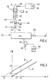
- the installation includes a plasma torch 54 according to the invention, for example similar to the torch described in the context of FIGS. 1 and 2, associated with a high frequency current generator 56, and at a photodetector 58 itself connected to a processing unit 60.
- cylindrical sleeve torch 54 external is supplied with Argon (Ar) for create a plasma preferably at atmospheric pressure or slight depression.
- the injector 62 intended to allow the introduction into the plasma of the gas to be analyzed is connected to a first mixer 64 comprising a first input 66 supplied with an inert gas, such as Argon, allowing to increase the gas drive speed to analyze, and a second input 68 connected to the output a second mixer 70.
- a first mixer 64 comprising a first input 66 supplied with an inert gas, such as Argon, allowing to increase the gas drive speed to analyze, and a second input 68 connected to the output a second mixer 70.
- Unit 76 has an entrance for admission aerosols from unit 78.
- Unit 78 also has a gas inlet 86 allowing the admission of an inert gas such as argon.
- the elements to be dosed at a known concentration and in a given form (liquid, solid or gaseous) closest to that of elements to be determined in the gas samples G.
- the polluting elements can be in the form solid or gaseous, and more rarely liquid.
- solid particles often present in chemical gases are less than one micron in size. For such a dimension, these small particles are rapidly volatilized and generate in an Argon plasma a light intensity identical to that generated by gaseous compounds.
- gas 86 for example argon transports this aerosol to the desolvation unit.
- the standard samples thus created are trained in plasma P by a gas similar to gas G, but lacking impurity, or by Argon.
- the light intensity emitted by the impurities is detected by photodetector 58 (monochromator and / or polychromator) then stored in a memory 84 of the unit analysis 60.
- the gas G is presented at the input of mixer 70 and is injected into the plasma P.
- the light intensity emitted by the impurities of gas G is then presented at the input of the analysis unit 60.
- the latter includes means of calculation of the type classic, ensuring the comparison between the intensity light detected impurities to be measured and the values of reference previously obtained and stored in the memory 84.
- the exact concentration of particles in the gas G is thus for example obtained by identification of the sample whose corresponding signal has a wavelength and intensity identical to the values measured from gas G.
- Figure 6 represents a schematic view in axial section of a torch plasma according to the invention, incorporating at the level of sleeve an intermediate tube.
- the torch shown in Figure 6 indeed has a tube intermediate 40, coaxial with the sleeve 42, located between the outer and inner walls of the sleeve (42A and 42B), the tube intermediate 40 and the outer wall 42A of the sleeve delimiting a gas supply channel 45 protection of the external wall (42A) of the torch against solid deposits.
- the torch shown in Figure 6 is provided with a winding 46 supplied by a current source at high frequency 48 and placed in the vicinity of the unit end of the torch, and a photodetector 50 connected to a processing unit 52.
- the supply channel 45 is therefore connected to a shielding gas supply source (not shown) able to react with species likely to deposit on the internal surface of the external wall 42A of the torch to form a volatile compound.
- the gas to be analyzed comprises silane (SiH 4 )
- the shielding gas comprises chlorine, possibly mixed with argon, reacting with silicon to form SiCL 4 .
- the latter compound is a volatile species, any deposit based on silicon is thus avoided.
- the torch here comprises a central injector 38 a double-walled (38A, 38B) for injecting part of the gas to analyze and on the other hand a "guide" gas.
Landscapes
- Physics & Mathematics (AREA)
- Engineering & Computer Science (AREA)
- Plasma & Fusion (AREA)
- Electromagnetism (AREA)
- Spectroscopy & Molecular Physics (AREA)
- Investigating, Analyzing Materials By Fluorescence Or Luminescence (AREA)
- Other Investigation Or Analysis Of Materials By Electrical Means (AREA)
- Plasma Technology (AREA)
Applications Claiming Priority (4)
| Application Number | Priority Date | Filing Date | Title |
|---|---|---|---|
| FR9716619 | 1997-12-29 | ||
| FR9716620A FR2773300B1 (fr) | 1997-12-29 | 1997-12-29 | Torche a plasma et installation d'analyse de gaz utilisant une telle torche |
| FR9716619A FR2773299B1 (fr) | 1997-12-29 | 1997-12-29 | Torche a plasma a injecteur reglable et installation d'analyse d'un gaz utilisant une telle torche |
| FR9716620 | 1997-12-29 |
Publications (1)
| Publication Number | Publication Date |
|---|---|
| EP0930810A1 true EP0930810A1 (de) | 1999-07-21 |
Family
ID=26234031
Family Applications (1)
| Application Number | Title | Priority Date | Filing Date |
|---|---|---|---|
| EP98402992A Withdrawn EP0930810A1 (de) | 1997-12-29 | 1998-11-30 | Plasmabrenner mit Verstellbarer Verteilung und Gasanalysenanlage die diesen Brenner gebraucht |
Country Status (7)
| Country | Link |
|---|---|
| US (1) | US6236012B1 (de) |
| EP (1) | EP0930810A1 (de) |
| JP (1) | JPH11248632A (de) |
| KR (1) | KR19990063580A (de) |
| CN (1) | CN1235274A (de) |
| SG (1) | SG71892A1 (de) |
| TW (1) | TW412636B (de) |
Families Citing this family (12)
| Publication number | Priority date | Publication date | Assignee | Title |
|---|---|---|---|---|
| US7511246B2 (en) | 2002-12-12 | 2009-03-31 | Perkinelmer Las Inc. | Induction device for generating a plasma |
| WO2006099190A2 (en) * | 2005-03-11 | 2006-09-21 | Perkinelmer, Inc. | Plasmas and methods of using them |
| US7742167B2 (en) | 2005-06-17 | 2010-06-22 | Perkinelmer Health Sciences, Inc. | Optical emission device with boost device |
| US8622735B2 (en) * | 2005-06-17 | 2014-01-07 | Perkinelmer Health Sciences, Inc. | Boost devices and methods of using them |
| JP4489680B2 (ja) * | 2005-10-03 | 2010-06-23 | 株式会社アドテック プラズマ テクノロジー | マイクロ波プラズマ発生方法および装置 |
| DE102006037995B4 (de) * | 2006-08-14 | 2009-11-12 | Bundesanstalt für Materialforschung und -Prüfung (BAM) | Analyseverfahren für Festkörperproben und Vorrichtung zur Durchführung desselben |
| FR2928641B1 (fr) * | 2008-03-14 | 2010-03-26 | Centre Nat Rech Scient | Procede de purification de silicium pour applications photovoltaiques |
| JP5965743B2 (ja) * | 2012-06-27 | 2016-08-10 | 株式会社日立ハイテクサイエンス | Icp装置及び分光分析装置並びに質量分析装置 |
| US9259798B2 (en) | 2012-07-13 | 2016-02-16 | Perkinelmer Health Sciences, Inc. | Torches and methods of using them |
| CN104363689B (zh) * | 2014-11-18 | 2017-02-08 | 聚光科技(杭州)股份有限公司 | 一种分析电源、矿粉分析装置及方法 |
| EP4321852A3 (de) * | 2014-12-29 | 2024-05-29 | Fluidigm Canada Inc. | Massenzytometrievorrichtung und -verfahren |
| CN119845862B (zh) * | 2025-03-18 | 2025-08-15 | 广饶齐成新能源有限公司 | 一种水样总磷检测装置及检测方法 |
Citations (8)
| Publication number | Priority date | Publication date | Assignee | Title |
|---|---|---|---|---|
| JPS60201239A (ja) * | 1984-03-26 | 1985-10-11 | Shimadzu Corp | Icp発光分光分析用プラズマト−チ |
| EP0263031A2 (de) * | 1986-10-03 | 1988-04-06 | Commissariat A L'energie Atomique | Induktiv gekoppelte Luft-Plasma-Vorrichtung für die spektrometrische Analyse von Elementen |
| US4766287A (en) * | 1987-03-06 | 1988-08-23 | The Perkin-Elmer Corporation | Inductively coupled plasma torch with adjustable sample injector |
| JPS63210754A (ja) * | 1987-02-27 | 1988-09-01 | Shimadzu Corp | Icp発光分析用試料導入装置 |
| EP0296921A1 (de) * | 1987-06-10 | 1988-12-28 | L'air Liquide, Societe Anonyme Pour L'etude Et L'exploitation Des Procedes Georges Claude | Mikrowellenplasmabrenner, einen solchen Brenner aufweisende Anlage und sie verwendendes Puderproduktionsverfahren |
| EP0358212A2 (de) * | 1988-09-09 | 1990-03-14 | Matheson Gas Products, Inc. | Einführsystem für reaktive Gasproben in einen Plasmabrenner mit induktiv angekoppeltem Plasma |
| EP0397468A2 (de) * | 1989-05-09 | 1990-11-14 | Varian Associates, Inc. | Spektroskopischer Plasmabrenner für Mikrowellenplasma |
| JPH05180772A (ja) * | 1991-12-27 | 1993-07-23 | Nkk Corp | レーザー気化/誘導結合プラズマ分析方法及びプラズマ トーチ |
Family Cites Families (6)
| Publication number | Priority date | Publication date | Assignee | Title |
|---|---|---|---|---|
| US4482246A (en) * | 1982-09-20 | 1984-11-13 | Meyer Gerhard A | Inductively coupled plasma discharge in flowing non-argon gas at atmospheric pressure for spectrochemical analysis |
| JPS59182345A (ja) | 1983-03-31 | 1984-10-17 | Shimadzu Corp | 液体クロマトグラフ発光分析装置 |
| US5051557A (en) * | 1989-06-07 | 1991-09-24 | The United States Of America As Represented By The Secretary Of The Department Of Health And Human Services | Microwave induced plasma torch with tantalum injector probe |
| GB8917570D0 (en) * | 1989-08-01 | 1989-09-13 | Vg Instr Group | Plasma source mass spectrometry |
| US5233156A (en) * | 1991-08-28 | 1993-08-03 | Cetac Technologies Inc. | High solids content sample torches and method of use |
| US5908566A (en) * | 1997-09-17 | 1999-06-01 | The United States Of America As Represented By The Secretary Of The Navy | Modified plasma torch design for introducing sample air into inductively coupled plasma |
-
1998
- 1998-11-30 EP EP98402992A patent/EP0930810A1/de not_active Withdrawn
- 1998-12-11 TW TW087120614A patent/TW412636B/zh not_active IP Right Cessation
- 1998-12-22 SG SG1998005896A patent/SG71892A1/en unknown
- 1998-12-25 JP JP10370101A patent/JPH11248632A/ja active Pending
- 1998-12-28 US US09/221,163 patent/US6236012B1/en not_active Expired - Fee Related
- 1998-12-28 KR KR1019980063916A patent/KR19990063580A/ko not_active Withdrawn
- 1998-12-29 CN CN98126221.XA patent/CN1235274A/zh active Pending
Patent Citations (8)
| Publication number | Priority date | Publication date | Assignee | Title |
|---|---|---|---|---|
| JPS60201239A (ja) * | 1984-03-26 | 1985-10-11 | Shimadzu Corp | Icp発光分光分析用プラズマト−チ |
| EP0263031A2 (de) * | 1986-10-03 | 1988-04-06 | Commissariat A L'energie Atomique | Induktiv gekoppelte Luft-Plasma-Vorrichtung für die spektrometrische Analyse von Elementen |
| JPS63210754A (ja) * | 1987-02-27 | 1988-09-01 | Shimadzu Corp | Icp発光分析用試料導入装置 |
| US4766287A (en) * | 1987-03-06 | 1988-08-23 | The Perkin-Elmer Corporation | Inductively coupled plasma torch with adjustable sample injector |
| EP0296921A1 (de) * | 1987-06-10 | 1988-12-28 | L'air Liquide, Societe Anonyme Pour L'etude Et L'exploitation Des Procedes Georges Claude | Mikrowellenplasmabrenner, einen solchen Brenner aufweisende Anlage und sie verwendendes Puderproduktionsverfahren |
| EP0358212A2 (de) * | 1988-09-09 | 1990-03-14 | Matheson Gas Products, Inc. | Einführsystem für reaktive Gasproben in einen Plasmabrenner mit induktiv angekoppeltem Plasma |
| EP0397468A2 (de) * | 1989-05-09 | 1990-11-14 | Varian Associates, Inc. | Spektroskopischer Plasmabrenner für Mikrowellenplasma |
| JPH05180772A (ja) * | 1991-12-27 | 1993-07-23 | Nkk Corp | レーザー気化/誘導結合プラズマ分析方法及びプラズマ トーチ |
Non-Patent Citations (2)
| Title |
|---|
| PATENT ABSTRACTS OF JAPAN vol. 013, no. 001 (P - 808) 6 January 1989 (1989-01-06) * |
| TRASSY ET AL.: "Dosage d'éléments métalliques dans le gaz. Etude d'une méthode directe.", JOURNAL OF HIGH TEMPERATURE CHEMICAL PROCESSES., no. 2, December 1993 (1993-12-01), pages 439 - 447, XP002076765 * |
Also Published As
| Publication number | Publication date |
|---|---|
| CN1235274A (zh) | 1999-11-17 |
| SG71892A1 (en) | 2000-04-18 |
| JPH11248632A (ja) | 1999-09-17 |
| KR19990063580A (ko) | 1999-07-26 |
| US6236012B1 (en) | 2001-05-22 |
| TW412636B (en) | 2000-11-21 |
Similar Documents
| Publication | Publication Date | Title |
|---|---|---|
| EP0930810A1 (de) | Plasmabrenner mit Verstellbarer Verteilung und Gasanalysenanlage die diesen Brenner gebraucht | |
| EP2195643B1 (de) | System zur analyse eines niederdruckgases mittels optischer emissionsspektroskopie | |
| CA1194385A (en) | Device fabrication using gas-solid processes | |
| Wiltsche et al. | Matrix effects of carbon and bromine in inductively coupled plasma optical emission spectrometry | |
| JP2002184767A (ja) | 内部の水分レベルを制御するための半導体処理装置および方法 | |
| Brockhinke et al. | Quantitative one-dimensional single-pulse multi-species concentration and temperature measurement in the lift-off region of a turbulent H2/air diffusion flame | |
| JP2016530502A (ja) | 質量分析計、その使用、およびガス混合物の質量分析検査の方法 | |
| US20090301655A1 (en) | Plasma Processing Apparatus | |
| EP3146314B1 (de) | Vorrichtung zur analyse eines oxidierbaren geschmolzenen metalls mit einer libs-technik | |
| CN105190830A (zh) | 用于控制谱法用等离子体的方法和装置 | |
| WO2014049291A1 (fr) | Methode et systeme d'analyse de particules dans un plasma froid | |
| EP2434275B1 (de) | Verfahren zur Messung einer organischen Feststoff-Probe oder einer Poymerfeststoffprobe mittels Glimmentladungsspektrometrie | |
| FR2773299A1 (fr) | Torche a plasma a injecteur reglable et installation d'analyse d'un gaz utilisant une telle torche | |
| FR2773300A1 (fr) | Torche a plasma et installation d'analyse de gaz utilisant une telle torche | |
| EP1549933A1 (de) | Verfahren und einrichtung zur spektroskopie der optischen emission einer durch einen laser erregten fl ssigkeit | |
| FR2553574A1 (fr) | Dispositif de regulation d'un courant d'ions notamment metalliques fortement charges | |
| CN1155655A (zh) | 腔废气监测系统、半导体加工系统,以及使用方法 | |
| FR3089299A1 (fr) | Methode d’analyse de fumees d’evaporation, produit programme d’ordinateur, systeme d’analyse et installation de fabrication additive associes | |
| EP0051152B1 (de) | Optische Kupplungseinrichtung | |
| EP0446080B1 (de) | Verfahren und Gerät zur elementaren Analyse einer Probe mittels Massenspektrometrie, gekoppelt mit einem durch Hochfrequenz induzierten Plasma | |
| JP2002039941A (ja) | 溶融金属中の成分の分析方法および分析装置 | |
| EP3861328A1 (de) | Verfahren zur analyse von verdampfungsgasen, computerprogrammprodukt, analysesystem und damit verbundene generative fertigungseinrichtung | |
| EP0200645B1 (de) | Verfahren und Probeneinlassvorichtung für ein Massenspektrometer | |
| JP2003075408A (ja) | 固体試料の金属元素分析方法およびその分析装置 | |
| Timmins | Excitation of gallium, indium, selenium, tellurium, arsenic and antimony in a helium microwave-induced plasma |
Legal Events
| Date | Code | Title | Description |
|---|---|---|---|
| PUAI | Public reference made under article 153(3) epc to a published international application that has entered the european phase |
Free format text: ORIGINAL CODE: 0009012 |
|
| AK | Designated contracting states |
Kind code of ref document: A1 Designated state(s): BE DE FR GB IE IT NL SE |
|
| AX | Request for extension of the european patent |
Free format text: AL;LT;LV;MK;RO;SI |
|
| 17P | Request for examination filed |
Effective date: 20000121 |
|
| AKX | Designation fees paid |
Free format text: BE DE FR GB IE IT NL SE |
|
| RAP1 | Party data changed (applicant data changed or rights of an application transferred) |
Owner name: L'AIR LIQUIDE, S.A. A DIRECTOIRE ET CONSEIL DE SUR |
|
| GRAH | Despatch of communication of intention to grant a patent |
Free format text: ORIGINAL CODE: EPIDOS IGRA |
|
| STAA | Information on the status of an ep patent application or granted ep patent |
Free format text: STATUS: THE APPLICATION HAS BEEN WITHDRAWN |
|
| 18W | Application withdrawn |
Effective date: 20030203 |