EP0397794B1 - Vorrichtung zur intubation der perkutanen endoskopischen ostomie - Google Patents
Vorrichtung zur intubation der perkutanen endoskopischen ostomie Download PDFInfo
- Publication number
- EP0397794B1 EP0397794B1 EP89902711A EP89902711A EP0397794B1 EP 0397794 B1 EP0397794 B1 EP 0397794B1 EP 89902711 A EP89902711 A EP 89902711A EP 89902711 A EP89902711 A EP 89902711A EP 0397794 B1 EP0397794 B1 EP 0397794B1
- Authority
- EP
- European Patent Office
- Prior art keywords
- tube
- inflation lumen
- cuff
- lumen
- port
- Prior art date
- Legal status (The legal status is an assumption and is not a legal conclusion. Google has not performed a legal analysis and makes no representation as to the accuracy of the status listed.)
- Expired - Lifetime
Links
Images


Classifications
-
- A—HUMAN NECESSITIES
- A61—MEDICAL OR VETERINARY SCIENCE; HYGIENE
- A61J—CONTAINERS SPECIALLY ADAPTED FOR MEDICAL OR PHARMACEUTICAL PURPOSES; DEVICES OR METHODS SPECIALLY ADAPTED FOR BRINGING PHARMACEUTICAL PRODUCTS INTO PARTICULAR PHYSICAL OR ADMINISTERING FORMS; DEVICES FOR ADMINISTERING FOOD OR MEDICINES ORALLY; BABY COMFORTERS; DEVICES FOR RECEIVING SPITTLE
- A61J15/00—Feeding-tubes for therapeutic purposes
- A61J15/0015—Gastrostomy feeding-tubes
- A61J15/0019—Gastrostomy feeding-tubes inserted by using a pull-wire
-
- A—HUMAN NECESSITIES
- A61—MEDICAL OR VETERINARY SCIENCE; HYGIENE
- A61J—CONTAINERS SPECIALLY ADAPTED FOR MEDICAL OR PHARMACEUTICAL PURPOSES; DEVICES OR METHODS SPECIALLY ADAPTED FOR BRINGING PHARMACEUTICAL PRODUCTS INTO PARTICULAR PHYSICAL OR ADMINISTERING FORMS; DEVICES FOR ADMINISTERING FOOD OR MEDICINES ORALLY; BABY COMFORTERS; DEVICES FOR RECEIVING SPITTLE
- A61J15/00—Feeding-tubes for therapeutic purposes
- A61J15/0026—Parts, details or accessories for feeding-tubes
- A61J15/003—Means for fixing the tube inside the body, e.g. balloons, retaining means
- A61J15/0034—Retainers adjacent to a body opening to prevent that the tube slips through, e.g. bolsters
- A61J15/0038—Retainers adjacent to a body opening to prevent that the tube slips through, e.g. bolsters expandable, e.g. umbrella type
- A61J15/0042—Retainers adjacent to a body opening to prevent that the tube slips through, e.g. bolsters expandable, e.g. umbrella type inflatable
-
- A—HUMAN NECESSITIES
- A61—MEDICAL OR VETERINARY SCIENCE; HYGIENE
- A61M—DEVICES FOR INTRODUCING MEDIA INTO, OR ONTO, THE BODY; DEVICES FOR TRANSDUCING BODY MEDIA OR FOR TAKING MEDIA FROM THE BODY; DEVICES FOR PRODUCING OR ENDING SLEEP OR STUPOR
- A61M25/00—Catheters; Hollow probes
- A61M25/10—Balloon catheters
-
- A—HUMAN NECESSITIES
- A61—MEDICAL OR VETERINARY SCIENCE; HYGIENE
- A61J—CONTAINERS SPECIALLY ADAPTED FOR MEDICAL OR PHARMACEUTICAL PURPOSES; DEVICES OR METHODS SPECIALLY ADAPTED FOR BRINGING PHARMACEUTICAL PRODUCTS INTO PARTICULAR PHYSICAL OR ADMINISTERING FORMS; DEVICES FOR ADMINISTERING FOOD OR MEDICINES ORALLY; BABY COMFORTERS; DEVICES FOR RECEIVING SPITTLE
- A61J15/00—Feeding-tubes for therapeutic purposes
- A61J15/0026—Parts, details or accessories for feeding-tubes
- A61J15/0073—Multi-lumen tubes
Definitions
- the present invention relates to a device for intubating an ostomy such as a gastronomy formed by a percutaneous endoscopic technique.
- Such devices are described in e.g. DE-U-8705 894. However, it is impossible to draw the device in a retrograde manner through the patient. Such drawing through the patient can be carried out by another device according to DE-A 3 444 909; However, this device is relatively complicated.
- the invention allows to easily and comfortably remove an anchoring and retention tip at the conclusion of enteral feeding therapy through the gastrostomy.
- the device of the present inventions meets the foregoing described needs by employing a multi-lumen enteral feeding tube, preferably having at least a fluid delivery lumen and an inflation lumen.
- the tube includes a port near one end to dispose the inflation lumen to ambient air and an outlet at an other end to convey fluid from within the fluid lumen into the patient.
- a retention member preferably an inflatable cuff, is joined near the other end of the tube.
- the cuff is substantially filled with a resilient porous material for maintaining the walls of the cuff in a fully inflated position.
- the retention cuff is in communication with the inflation lumen and is inflatable and deflatable through the inflation lumen.
- the walls of the cuff are designed so that in a deflated state, the cuff assumes an edge-free, preferably rounded, outer configuration to facilitate a comfortable intubation of the device into the patient.
- the cuff in a fully inflated state, assumes an outer configuration defining at least one generally flat surface to more diffusely contact and abut against the inner tissue surfaces surrounding the gastrostomy.
- an elongated tapered sleeve Joined to the one end of the tube is an elongated tapered sleeve which encloses the one end of the tube.
- the tapered end of the sleeve carries, preferably, a suture loop for use in intubating the device.
- the sleeve includes a skirt portion which creates a circumferential airtight seal about the exterior of the tube to selectively seal the ambient air port.
- the skirt portion of the sleeve is air pressure responsive to permit escape of air from the inflation lumen through the port but preventing the ingress of air into the inflation lumen through the port.
- the ambient air port is sealed by a frangible plug member.
- the frangible plug member generally includes a stem frangibly connected to an enlarged gripping portion.
- the device of the present invention is utilized in intubating a gastrostomy formed by a percutaneous endoscopic technique by the following steps.
- the cuff is deflated by compressing it, thereby expelling air out of the inflation lumen through the port.
- the skirt portion of the sleeve expands outwardly in response to the greater air pressure within the lumen to permit the escape of air out of the inflation lumen through the port.
- the air pressure within the inflation lumen decreases relative to ambient air pressure such that the skirt portion contracts inwardly to seal the ambient air port thus preventing ingress of air into the inflation lumen.
- the ambient air port may be sealed by inserting the stem of the frangible plug member into the port.
- the stem is inserted into the inflation lumen to a point such that when the frangible connection between the stem portion is broken, the stem remains in the port to occlude the inflation lumen.
- Initial deflation of the retention cuff may be accomplished by manually squeezing the cuff.
- the present invention provides for initial deflation of the cuff through use of a circular deflation strap. The cuff is captivated within the deflation strap and the strap is then tightened thus deflating the cuff and maintaining it in a deflated position until the ambient art port is sealed.
- the deflation strap is particularly useful in the embodiment of the present invention wherein a frangible plug is utilized for initial sealing of the inflation lumen.
- the retention cuff In a deflated state, the retention cuff assumes an edge free generally oval outer configuration.
- the suture loop carried on the tapered end of the sleeve is tied to the one end of the suture which extends from the patient's mouth.
- the gastroenterologist then begins pulling on the other end of the suture extending externally from the gastrostomy to lead the device in a retrograde manner through the mouth, esophagus and ultimately into the stomach.
- the retrograde drawing of the device continues until the deflated cuff abuts against inner tissue surfaces surrounding the gastrostomy. Air is then externally introduced into the inflation lumen to re-inflate the retention cuff to change the outer configuration of the cuff to create a generally flat anchor surface.
- re-inflation of the cuff may be achieved by severing the multi-lumen tube below the sleeve to remove the sleeve from the tube. This exposes the inflation lumen to ambient air resulting in re-inflation of the cuff.
- the multi-lumen tube may be similarly severed below the plugged area of the inflation lumen.
- the inflation lumen should be sealed with a plug, such as another frangible plug member, or other device to prevent deflation of the retention cuff.
- a plug such as another frangible plug member, or other device to prevent deflation of the retention cuff.
- the severed end of the multi-lumen tube is secured at the exterior of the ostomy by means known in the art such as by tape or suture. This prevents the inflated cuff from dislodging from the tissue wall and to keep the cuff urged against the inner tissue surface surrounding the ostomy.
- a luer adaptor or other tube connecting device may be affixed to the severed end of.the tube to place the tube in fluid communication with an enteral nutritional fluid source.
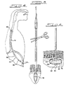
- FIG. 1 discloses one embodiment of device 10 of the present invention comprised of a multi-lumen enteral feeding tube.
- feeding tube 12 includes at least an inflation lumen 14 and a fluid delivery lumen 16. Lumens 14 and 16 are separated by a septum 18.
- one end 12A of tube 12 has at least one ambient air port 20 which, as will be disclosed later in greater detail, disposes inflation lumen 14 in communication with ambient air.
- the fluid outlet 22 (shown in phantom in FIG. 2) conveys fluid from fluid lumen 16 into a patient.
- an enclosed sleeve 24 preferably having a tapered elongated conical terminal end 26.
- the tapered conical outer configuration of terminal end 26 permits atraumatic parting of esophageal and gastric tissues during the intubation process.
- a suture loop 28 disposed on the terminal end 26 of sleeve 24 is a suture loop 28 which permits device 10 to be tied to the end of the suture extending from the patient's mouth during the percutaneous endoscopic technique (not shown in the drawings).
- suture loop 28 may preferably fully extend through sleeve 24 through a channel 32 and be secured to end 12A of tube 12 by a fastening knot or other fastening device 34 secured to the septum 18.
- FIGS. 1 through 3A disclose one preferred embodiment of the present invention wherein, joined to sleeve 24, is a skirt portion 36 which circumferentially surrounds end 12A of tube 12 in such a manner to create an airtight seal between skirt portion 36 and outer surfaces of end 12A.
- Skirt portion 36 is made from a highly pliable plastic or latex rubber so as to be air pressure responsive permitting selective sealing of ambient air port 20.
- skirt portion 36 responds to greater air pressure within inflation lumen 14 to permit the escape of air out of lumen 14 through port 20
- skirt portion 36 contracts inwardly to seal port 20 to prevent the further ingress of air into lumen 14.
- FIGS. 3 and 3A disclose in greater detail the selective sealing or diaphragmatic action of skirt portion 36.
- skirt 36 when air pressure within inflation lumen 14 increases to exceed ambient air pressure, skirt 36 expands outwardly away from the walls of tube 12 to define a circumferential gap 38 which permits air to exit ambient port 20 and escape from under skirt portion 36.
- skirt portion 36 contracts circumferentially about tube 12 closing gap 38 and thereby forming an airtight seal about tube 12 and port 20.
- a retention/anchor member which preferably is embodied as an annular cuff 40.
- retention cuff 40 is affixed to the other end 12B of tube 12.
- Retention cuff 40 is sealed and in gas communication with inflation lumen 14 through a terminal opening 42 in tube 12.
- tube 12 passes through cuff 40 so that, as disclosed in FIG. 6, fluid outlet 22 extends below cuff 40.
- cuff 40 is comprised of a distendable outer wall 40 which defines a cavity preferably substantially filled with a porous resilient foam material 46. As disclosed in FIG. 6, foam material 46 is cut in a configuration so that when cuff 40 is in a fully expanded position, foam material 46 maintains walls 44 in expanded position.
- Retention cuff 40 is placed in a deflated state by compressing, preferably by squeezing, cuff 40 so that the air trapped within walls 44 and foam material 46 is expelled upwardly into the inflation lumen and out of port 20. Discontinuing such squeezing of cuff 40 results in a decrease in air pressure within inflation lumen 14 so that ambient air pressure acts upon skirt 36 to seal port 20 in the manner described above. Such sealing of port 20 prevents re-inflation of retention cuff 40 and maintains cuff 40 in a deflated position. Re-inflation of cuff 40 is achieved by introducing ambient air into inflation lumen 14 by methods to be described below in greater detail.
- Cuff 40 combines in a single structure both the retention and anchoring functions achieved by prior art catheter mushroom-type tips and perpendicular rubber bumpers.
- cuff 40 in a deflated state assumes an essentially edge-free, rounded configuration which facilitates intubation of device 10.
- Cuff 40, in a deflated state preferably assumes a oval or pill-shape as disclosed in FIGS. 1 and 2.
- cuff 40 In a fully inflated state, cuff 40 assumes a different configuration.
- the walls 44 of cuff 40 are molded or pre-formed so that the outer configuration of cuff 40 changes from a deflated state to a fully inflated state.
- cuff 40 includes a fold or crease line 48 which changes the outer configuration of cuff 40 from deflation to full inflation.
- fold line 48 defines a peripheral edge of a generally flat retention and anchor surface 50.
- Surface 50 is of a sufficient surface area to evenly distribute contact pressures on the tissue surrounding the gastrostomy to avoid the necrosis of tissue commonly encountered by use of prior art retention bumpers.
- a novel aspect of the present invention is that the retention cuff, in a deflated position, has an edge-free contour to facilitate a comfortable intubation, whereas, in a fully inflated state, retention cuff 40 assumes a different configuration to define an edged, flattened surface for anchoring tube 12 within the gastrostomy.
- FIGS. 4 through 6 disclose the general method of using device 10 in intubating an ostomy formed by a percutaneous endoscopic technique.
- the suture is tied to loop 28 of the device of the present invention.
- the device of the present invention is then drawn downward through the mouth, esophagus and into the stomach in a retrograde manner. The pulling of the suture through the gastrostomy continues until the deflated retention cuff 40 abuts against the inner tissue surfaces of the gastrostomy as disclosed in FIG. 5.
- retention cuff 40 is re-inflated by introducing air into the inflation lumen 14 and then the inflation lumen 14 is sealed as disclosed below to prevent inadvertent deflation.
- the exposed portion of tube 12 is then secured near the external tissue surface of the ostomy to maintain the position of the retention cuff 40 against the inner tissue surrounding the ostomy, as disclosed in FIG. 6.
- the exposed portion may be secured by conventional means such as by tape or suture 51 the tube 12 to the external tissue.
- re-inflation of the retention cuff 40 may be accomplished by severing, as disclosed in FIG. 5, completely through a portion of tube 12 external to the gastrostomy.
- inflation lumen 14 is exposed to ambient air thereby raising the air pressure within lumen 14 to automatically inflate cuff 40.
- it may be necessary to assist the inflation operation by injecting air into inflation lumen 14 through the insertion of the tip of an air-filled syringe into inflation lumen 14.
- inflation lumen 14 is sealed with a plug or other device to prevent deflation of cuff 40, such as frangible plug 60 of FIG. 8 which will be disclosed in more detail below.
- a luer adaptor or other tube connection means may be affixed to the severed end of tube 12 to join tube 12 to a source of enteral nutritional fluid. It should be noted that such adaptor or tube connection means may also function to seal inflation lumen 14.
- FIGS. 7 through 10 disclose another preferred embodiment of the present invention.
- a multi-lumen enteral feeding tube 10 as previously disclosed is provided wherein skirt 36 is omitted or rendered non-functional.
- tapered end 26 is nonetheless utilized to facilitate intubation.
- ambient-air port 20 is exposed rather than being concealed underneath skirt 36.
- initial sealing of the inflation lumen 14 is accomplished by occluding the lumen with a plug member of the type disclosed in FIG. 8 which is inserted into the lumen through ambient-air port 20.
- frangible plug 60 generally comprises a solid cylindrical stem 62 and an enlarged gripping portion 64 on one end of stem 62.
- a portion of stem 62 is crimped or narrowed to define a frangible region 66.
- the diameter of stem 62 is dimensioned to permit an interference fit with the inner diameter of inflation lumen 14.
- Frangible region 66 is adapted to allow gripping portion 64 to be twisted or bent to break-off stem 62 allowing the gripping portion to be removed.
- retention cuff 40 is compressed prior to intubation.
- inflation lumen 14 is occluded by inserting plug 60 into the inflation lumen while the cuff 40 is still compressed thus preventing premature re-inflation of the retention cuff.
- FIG. 10 best discloses that the frangible plug 60 is inserted through ambient port 20 to a position where frangible portion 66 is inside inflation lumen 14 so that when stem 62 is broken from gripping portion 64, stem 62 is totally enclosed with lumen 14 thus not presenting any protrusion which would cause damage during intubation.
- retention cuff 40 may be compressed by squeezing the cuff in the palm off one hand while holding tube 12 between the thumb and forefinger of the same hand leaving the other hand of the user free to grip the frangible plug for insertion while the cuff remains compressed.
- air may be introduced into the retention cuff 40 in a manner similar to that disclosed above by cutting the multi-lumen tube 12 below the occluded area.
- the retention cuff may be maintained in the re-inflated position by the insertion of another frangible plug member into the exposed open end of the inflation lumen 14.
- Cuff 40 may also be compressed and maintained in a compressed state by an adjustable strap 70 such as disclosed in FIG. 9.
- Strap 70 is a generally flat flexible member including a widened body portion 72, an integral narrowed tongue portion 74 on one end of the body portion which has a plurality of barbs 78 on the its edges and a slot 76 at an opposite end of the body portion.
- Body portion 72 is dimensioned to engage on a substantial portion of the outer surface of retention cuff 40.
- Tongue portion 74 is cooperatively dimensioned with slot 76 so that the tongue may be inserted into the slot and pulled therethrough with barbs 78 engaging the edges of the slot to prevent retrograde movement of the tongue.
- Utilization of the compression strap allows the user to more easily accomplish retaining the cuff in a compressed state until the lumen can be plugged. In certain instances, use of the compression strap may also provide a more aseptic means for compressing the retention cuff by avoiding contact of the cuff with the hands.
Landscapes
- Health & Medical Sciences (AREA)
- Life Sciences & Earth Sciences (AREA)
- Animal Behavior & Ethology (AREA)
- Veterinary Medicine (AREA)
- Public Health (AREA)
- General Health & Medical Sciences (AREA)
- Heart & Thoracic Surgery (AREA)
- Biophysics (AREA)
- Biomedical Technology (AREA)
- Hematology (AREA)
- Anesthesiology (AREA)
- Engineering & Computer Science (AREA)
- Pulmonology (AREA)
- Child & Adolescent Psychology (AREA)
- Gastroenterology & Hepatology (AREA)
- Media Introduction/Drainage Providing Device (AREA)
Claims (5)
- Vorrichtung zur Intubation einer künstlichen Fistel wie etwa einer Magenfistel, die mittels einer perkutanen Endoskoptechnik gebildet ist, wobei die Vorrichtung folgendes aufweist:
einen Tubus (12) mit wenigstens einem Fluidlumen (16) und einem Aufblaslumen (14), wobei der Tubus (12) eine Luftöffnung (20) nahe einem Ende (12A), um das Aufblaslumen (14) der Umgebungsluft auszusetzen, und einen Fluidauslaß (22) hat, um Fluid vom Inneren des Fluidlumens (16) in den Patienten zu fördern;
ein Rückhalteelement (40), das nahe einem anderen Ende (12B) des Tubus (12) daran angesetzt ist, wobei das Element durch das Aufblaslumen (14) aufblasbar ist, das Rückhalteelement (40) in einem entleerten Zustand eine im allgemeinen kantenfreie Außenkonfiguration zur leichteren Intubation hat und das Rückhalteelement (40) in einem aufgeblasenen Zustand wenigstens eine im allgemeinen flache Rückhalte- und Verankerungsfläche definiert;
eine Einrichtung (36, 62) zum Abdichten der Umgebungsluftöffnung (20) des Tubus (12);
wobei vor der Intubation das Rückhalteelement (40) zusammengedrückt wird, um das Element durch Ausstoßen von Luft aus dem Aufblaslumen (14) durch die Öffnung (22) zu entleeren, wobei die Abdichteinrichtung verwendet wird, um die Öffnung (20) abzudichten, um ein erneutes Aufblasen des Rückhalteelements (40) zu verhindern, und wobei Luft in das Aufblaslumen (14) eingeleitet wird, um das Rückhalteelement (40) erneut aufzublasen und die Vorrichtung in Anlage an den inneren Gewebsflächen der künstlichen Fistel zu verankern,
dadurch gekennzeichnet,
daß eine Hülse (24) mit dem einen Ende (12A) des Tubus (12) verbunden ist und das eine Ende abdichtet, wobei die Hülse (24) eine kantenfreie Außenkonfiguration hat, um gastroenterales Gewebe während der Intubation sanft zu teilen; daß der Fluidauslaß (22) an dem anderen Ende (12B) des Tubus (12) positioniert ist und die Vorrichtung derart ist, daß im Gebrauch das eine Ende (12A) des Tubus (12) rückschreitend durch den Patienten gezogen werden kann, bis das entleerte Rückhalteelement (40) an inneren Gewebsflächen der künstlichen Fistel anliegt, wonach die Abdichteinrichtung (36; 62) verwendet wird, um das Aufblaslumen (14) erneut abzudichten, um ein Entleeren des Rückhalteelements (40) zu verhindern. - Vorrichtung nach Anspruch 1, dadurch gekennzeichnet, daß die Abdichteinrichtung einen Mantelbereich (36) aufweist, der mit der Hülse (24) verbunden ist, wobei der Mantelbereich (36) eine luftdichte Abdichtung um den Umfang des Tubus (12) herum bildet und die Umgebungsluftöffnung (20) abdeckt, wobei der Mantelbereich (36) sich aufgrund von höherem Luftdruck in dem Aufblaslumen (14) nach außen ausdehnt, um ein Ausstoßen von Luft aus der Öffnung (20) zuzulassen, und sich aufgrund von höheren Luftdrücken an der Außenseite des Aufblaslumens (14) nach innen zusammenzieht, um die Öffnung (20) dicht zu verschließen.
- Vorrichtung nach Anspruch 1 oder 2, dadurch gekennzeichnet, daß das aufblasbare Rückhalteelement eine im wesentlichen schaumstoffgefüllte ringförmige Manschette (40) aufweist.
- Vorrichtung nach Anspruch 3, dadurch gekennzeichnet, daß die ringförmige Manschette (40) wenigstens eine im allgemeinen abgeflachte Oberfläche zur Anlage an den Innenflächen der Magenfistel hat.
- Vorrichtung nach einem der Ansprüche 1-4, dadurch gekennzeichnet, daß das terminale Ende der Hülse (24) eine konische Gestalt hat und eine Fadenschlinge an diesem terminalen Ende angebracht ist, um die Vorrichtung rückschreitend durch die Speiseröhre und die künstliche Fistel zu ziehen.
Applications Claiming Priority (4)
| Application Number | Priority Date | Filing Date | Title |
|---|---|---|---|
| US144527 | 1988-01-15 | ||
| US07/144,527 US4795430A (en) | 1988-01-15 | 1988-01-15 | Device for intubation of percutaneous endoscopic ostomy |
| US07/291,115 US4900306A (en) | 1988-01-15 | 1988-12-28 | Device for intubation of percutaneous endoscopic ostomy |
| US291115 | 1988-12-28 |
Publications (2)
| Publication Number | Publication Date |
|---|---|
| EP0397794A1 EP0397794A1 (de) | 1990-11-22 |
| EP0397794B1 true EP0397794B1 (de) | 1993-05-12 |
Family
ID=26842082
Family Applications (1)
| Application Number | Title | Priority Date | Filing Date |
|---|---|---|---|
| EP89902711A Expired - Lifetime EP0397794B1 (de) | 1988-01-15 | 1988-12-30 | Vorrichtung zur intubation der perkutanen endoskopischen ostomie |
Country Status (4)
| Country | Link |
|---|---|
| US (1) | US4900306A (de) |
| EP (1) | EP0397794B1 (de) |
| DE (1) | DE3881060T2 (de) |
| WO (1) | WO1989006529A1 (de) |
Families Citing this family (57)
| Publication number | Priority date | Publication date | Assignee | Title |
|---|---|---|---|---|
| US4981471A (en) * | 1988-01-15 | 1991-01-01 | Corpak, Inc. | Device for intubation of percutaneous endoscopic ostomy |
| US5125897A (en) * | 1990-04-27 | 1992-06-30 | Corpak, Inc. | Gastrostomy device with one-way valve and cuff pin |
| US5098396A (en) * | 1990-10-19 | 1992-03-24 | Taylor Ellis R | Valve for an intravascular catheter device |
| US5308325A (en) * | 1991-01-28 | 1994-05-03 | Corpak, Inc. | Retention balloon for percutaneous catheter |
| US5439444A (en) * | 1991-01-28 | 1995-08-08 | Corpak, Inc. | Pre-formed member for percutaneous catheter |
| US5112310A (en) * | 1991-02-06 | 1992-05-12 | Grobe James L | Apparatus and methods for percutaneous endoscopic gastrostomy |
| US5318530A (en) * | 1991-12-06 | 1994-06-07 | Bissel Medical Products, Inc. | Gastrointestinal tube with inflatable bolus |
| US5356391A (en) * | 1992-06-22 | 1994-10-18 | Medical Innovations Corp. | Flexible retainer flange for gastrostomy tube and the method of installing it |
| DE4236210C1 (de) * | 1992-10-27 | 1994-04-14 | Olympus Optical Europ | Schlauchförmiges Implantat zur Verwendung bei der perkutanen Nahrungszufuhr |
| US5451212A (en) * | 1994-01-21 | 1995-09-19 | Corpak, Inc. | Bumper retention device |
| US5720734A (en) * | 1994-02-28 | 1998-02-24 | Wilson-Cook Medical, Inc. | Gastrostomy feeding ports |
| US5556385A (en) * | 1994-12-06 | 1996-09-17 | Corpak, Inc. | Improved percutaneous access device |
| US6036673A (en) * | 1996-01-11 | 2000-03-14 | C. R. Bard, Inc. | Bolster for corporeal access tube assembly |
| US6077243A (en) * | 1996-01-11 | 2000-06-20 | C.R. Bard, Inc. | Retention balloon for a corporeal access tube assembly |
| US6066112A (en) * | 1996-01-11 | 2000-05-23 | Radius International Limited Partnership | Corporeal access tube assembly and method |
| US5860952A (en) * | 1996-01-11 | 1999-01-19 | C. R. Bard, Inc. | Corporeal access tube assembly and method |
| DE69733911T2 (de) * | 1996-01-11 | 2006-06-01 | C.R. Bard, Inc. | Röhrcheneinheit für Körperzugang |
| US5913816A (en) * | 1997-10-31 | 1999-06-22 | Imagyn Medical Technologies, Inc. | Intubation device and method |
| US6322538B1 (en) | 1999-02-18 | 2001-11-27 | Scimed Life Systems, Inc. | Gastro-intestinal tube placement device |
| US6511474B1 (en) * | 2000-07-12 | 2003-01-28 | Corpak, Inc. | Bolus for non-occluding high flow enteral feeding tube |
| US6960199B2 (en) * | 2000-12-14 | 2005-11-01 | J&R Medical Devices, Inc. | Method for feeding with a tube |
| US6743207B2 (en) | 2001-04-19 | 2004-06-01 | Scimed Life Systems, Inc. | Apparatus and method for the insertion of a medical device |
| US6673058B2 (en) | 2001-06-20 | 2004-01-06 | Scimed Life Systems, Inc. | Temporary dilating tip for gastro-intestinal tubes |
| US7048722B2 (en) * | 2001-11-16 | 2006-05-23 | Radius International Limited Partnership | Catheter |
| EP1446060B1 (de) | 2001-11-21 | 2006-03-22 | Boston Scientific Limited, A Corporation Duly Organized under the Laws of Ireland | Zugangsnadel zur perkutanen endoskopischen plazierung einer gastro/jejeunal-sonde |
| US20040158229A1 (en) * | 2002-01-24 | 2004-08-12 | Quinn David G. | Catheter assembly and method of catheter insertion |
| US7507230B2 (en) * | 2002-02-19 | 2009-03-24 | Boston Scientific Scimed, Inc. | Medical catheter assembly including multi-piece connector |
| US6802836B2 (en) * | 2002-02-19 | 2004-10-12 | Scimed Life Systems, Inc. | Low profile adaptor for use with a medical catheter |
| US20030225392A1 (en) * | 2002-05-31 | 2003-12-04 | Kimberly-Clark Worldwide, Inc. | Low profile transpyloric jejunostomy system and method to enable |
| US20030225369A1 (en) * | 2002-05-31 | 2003-12-04 | Kimberly-Clark Worldwide, Inc. | Low profile transpyloric jejunostomy system |
| US20030225393A1 (en) * | 2002-05-31 | 2003-12-04 | Kimberly-Clark Worldwide, Inc. | Low profile transpyloric jejunostomy system and method to enable |
| US20040054350A1 (en) * | 2002-09-17 | 2004-03-18 | Shaughnessy Michael C. | Enteral feeding unit having a reflux device and reflux method |
| AU2003290847A1 (en) * | 2002-11-15 | 2004-06-15 | Radius International Limited Partnership | Catheter |
| US6997900B2 (en) * | 2002-12-09 | 2006-02-14 | Scimed Life Systems, Inc. | Connector for use with a medical catheter and medical catheter assembly |
| US20040116899A1 (en) * | 2002-12-16 | 2004-06-17 | Shaughnessy Michael C. | Bolus for non-occluding high flow enteral feeding tube |
| US7654980B2 (en) * | 2004-05-14 | 2010-02-02 | Boston Scientific Scimed, Inc. | Method for percutaneously implanting a medical catheter and medical catheter implanting assembly |
| US20060030818A1 (en) * | 2004-08-09 | 2006-02-09 | Mcvey Robert D | System and method for securing a medical access device |
| US7976518B2 (en) | 2005-01-13 | 2011-07-12 | Corpak Medsystems, Inc. | Tubing assembly and signal generator placement control device and method for use with catheter guidance systems |
| US7914497B2 (en) * | 2005-01-26 | 2011-03-29 | Radius International Limited Partnership | Catheter |
| US20070060898A1 (en) * | 2005-09-07 | 2007-03-15 | Shaughnessy Michael C | Enteral medical treatment assembly having a safeguard against erroneous connection with an intravascular treatment system |
| US7985205B2 (en) * | 2005-09-14 | 2011-07-26 | Boston Scientific Scimed, Inc. | Medical catheter external bolster having strain relief member |
| US8021338B2 (en) | 2005-09-14 | 2011-09-20 | Boston Scientific Scimed, Inc. | Percutaneous endoscopic jejunostomy access needle |
| US8172801B2 (en) * | 2005-09-15 | 2012-05-08 | Boston Scientific Scimed, Inc. | Method for positioning a catheter guide element in a patient and kit for use in said method |
| US7967786B2 (en) * | 2005-09-15 | 2011-06-28 | Boston Scientific Scimed, Inc. | Access needle well-suited for percutaneous implantation in a body lumen |
| US8048062B2 (en) | 2005-12-30 | 2011-11-01 | Boston Scientific Scimed, Inc. | Catheter assembly and method for internally anchoring a catheter in a patient |
| US20070255222A1 (en) * | 2006-03-27 | 2007-11-01 | Changqing Li | Catheter assembly including internal bolster |
| US7547303B2 (en) * | 2006-08-03 | 2009-06-16 | Boston Scientific Scimed, Inc. | Catheter assembly including foldable internal bolster |
| USD561329S1 (en) | 2006-10-04 | 2008-02-05 | Kimberly-Clark Worldwide, Inc. | Low profile transpyloric jejunostomy catheter |
| US8157765B2 (en) | 2006-10-20 | 2012-04-17 | Boston Scientific Scimed, Inc. | Medical catheter assembly including a balloon bolster |
| WO2008121311A1 (en) * | 2007-03-29 | 2008-10-09 | Boston Scientific Scimed, Inc. | Catheter assembly including coiled internal bolster |
| WO2012023981A2 (en) * | 2010-08-17 | 2012-02-23 | St. Jude Medical, Inc. | Tip for medical implant delivery system |
| WO2013036772A1 (en) | 2011-09-08 | 2013-03-14 | Corpak Medsystems, Inc. | Apparatus and method used with guidance system for feeding and suctioning |
| US9386910B2 (en) | 2012-07-18 | 2016-07-12 | Apollo Endosurgery, Inc. | Endoscope overtube for insertion through a natural body orifice |
| US10744070B2 (en) | 2015-06-19 | 2020-08-18 | University Of Southern California | Enteral fast access tract platform system |
| WO2016205754A1 (en) | 2015-06-19 | 2016-12-22 | University Of Southern California | Compositions and methods for modified nutrient delivery |
| WO2018187235A1 (en) * | 2017-04-03 | 2018-10-11 | John Langell | Low-profile videoscopic speculum with working port |
| US12599544B2 (en) | 2024-05-09 | 2026-04-14 | Alsteni Medical, Inc. | Intraoral gastrointestinal access device and related methods |
Citations (1)
| Publication number | Priority date | Publication date | Assignee | Title |
|---|---|---|---|---|
| EP0256546A2 (de) * | 1986-08-18 | 1988-02-24 | Frimberger, Erintrud | Vorrichtung zum Plazieren eines Ernährungs-Schlauches am Magen des menschlichen oder tierischen Körpers |
Family Cites Families (15)
| Publication number | Priority date | Publication date | Assignee | Title |
|---|---|---|---|---|
| US3190291A (en) * | 1962-10-08 | 1965-06-22 | Frederic E B Foley | Self-inflating bag catheter |
| US3656485A (en) * | 1970-04-27 | 1972-04-18 | Jack R Robertson | Method of and apparatus for viewing the interior of the bladder through a suprapubic incision |
| US3640282A (en) * | 1970-08-06 | 1972-02-08 | Jack M Kamen | Tracheal tube with normally expanded balloon cuff |
| US3799173A (en) * | 1972-03-24 | 1974-03-26 | J Kamen | Tracheal tubes |
| US4141364A (en) * | 1977-03-18 | 1979-02-27 | Jorge Schultze | Expandable endotracheal or urethral tube |
| US4356824A (en) * | 1980-07-30 | 1982-11-02 | Vazquez Richard M | Multiple lumen gastrostomy tube |
| US4685901A (en) * | 1984-11-05 | 1987-08-11 | Medical Innovations Corporation | Gastro-jejunal feeding device |
| US4666433A (en) * | 1984-11-05 | 1987-05-19 | Medical Innovations Corporation | Gastrostomy feeding device |
| DE3444909A1 (de) * | 1984-12-08 | 1986-06-12 | Fresenius AG, 6380 Bad Homburg | Katheter fuer die enterale ernaehrung zur insbesondere intraduodenalen applikation mittels einer gastrostomie |
| US4642092A (en) * | 1984-12-10 | 1987-02-10 | Gerald Moss | Gastrointestinal aspirating device with suction breakers |
| US4758219A (en) * | 1985-05-17 | 1988-07-19 | Microvasive, Inc. | Enteral feeding device |
| US4668225A (en) * | 1985-12-23 | 1987-05-26 | Superior Healthcare Group, Inc. | Gastrostomy tube and gastrostomy-jejunal feeding tube combination |
| JPH0796654B2 (ja) * | 1986-08-20 | 1995-10-18 | 大日精化工業株式会社 | 顔料の分散方法 |
| DE8705894U1 (de) * | 1987-04-23 | 1987-06-19 | Fresenius AG, 6380 Bad Homburg | Gastral/duodenal-Katheter für die künstliche Ernährung |
| US4795430A (en) * | 1988-01-15 | 1989-01-03 | Corpak, Inc. | Device for intubation of percutaneous endoscopic ostomy |
-
1988
- 1988-12-28 US US07/291,115 patent/US4900306A/en not_active Expired - Lifetime
- 1988-12-30 WO PCT/US1988/004709 patent/WO1989006529A1/en not_active Ceased
- 1988-12-30 DE DE8989902711T patent/DE3881060T2/de not_active Expired - Fee Related
- 1988-12-30 EP EP89902711A patent/EP0397794B1/de not_active Expired - Lifetime
Patent Citations (1)
| Publication number | Priority date | Publication date | Assignee | Title |
|---|---|---|---|---|
| EP0256546A2 (de) * | 1986-08-18 | 1988-02-24 | Frimberger, Erintrud | Vorrichtung zum Plazieren eines Ernährungs-Schlauches am Magen des menschlichen oder tierischen Körpers |
Also Published As
| Publication number | Publication date |
|---|---|
| US4900306A (en) | 1990-02-13 |
| DE3881060T2 (de) | 1993-08-19 |
| WO1989006529A1 (en) | 1989-07-27 |
| EP0397794A1 (de) | 1990-11-22 |
| DE3881060D1 (de) | 1993-06-17 |
Similar Documents
| Publication | Publication Date | Title |
|---|---|---|
| EP0397794B1 (de) | Vorrichtung zur intubation der perkutanen endoskopischen ostomie | |
| US4795430A (en) | Device for intubation of percutaneous endoscopic ostomy | |
| US4981471A (en) | Device for intubation of percutaneous endoscopic ostomy | |
| US6027478A (en) | Nasal cavity drainage and stoppage system | |
| US4701163A (en) | Gastrostomy feeding device | |
| US4798592A (en) | Gastrostomy feeding device | |
| US4861334A (en) | Self-retaining gastrostomy tube | |
| US3933153A (en) | Intra-uterine contraceptive device | |
| US4877025A (en) | Tracheostomy tube valve apparatus | |
| US4655214A (en) | Inflatable introducer for aiding the intubation of catheters and endotracheal tubes | |
| US4976261A (en) | Endotracheal tube with inflatable cuffs | |
| US5011474A (en) | Methods for controlling nasal hemorrhaging | |
| US5454817A (en) | Oto-nasal foreign body extractor | |
| US5997546A (en) | Gastric balloon catheter with improved balloon orientation | |
| US5054484A (en) | Tracheostomy device | |
| US3516407A (en) | Inflatable intranasal tampon | |
| US4488548A (en) | Endotracheal tube assembly | |
| US4338941A (en) | Apparatus for arresting posterior nosebleeds | |
| US5084014A (en) | Package for initial placement of low profile gastrostomy device and method of placement | |
| US4842583A (en) | Colonic irrigation tube | |
| US20030139703A1 (en) | Tube device for feeding and method for the same | |
| JP2004504866A (ja) | 高さが低い腸フィステル形成器具 | |
| JPH09508542A (ja) | 改良された内部保持部材を有する胃フィステル形成管 | |
| US5100384A (en) | Method and device for percutaneous intubation | |
| US5871467A (en) | Post-pyloric feeding tubes |
Legal Events
| Date | Code | Title | Description |
|---|---|---|---|
| PUAI | Public reference made under article 153(3) epc to a published international application that has entered the european phase |
Free format text: ORIGINAL CODE: 0009012 |
|
| 17P | Request for examination filed |
Effective date: 19900703 |
|
| AK | Designated contracting states |
Kind code of ref document: A1 Designated state(s): DE FR GB |
|
| 17Q | First examination report despatched |
Effective date: 19911115 |
|
| GRAA | (expected) grant |
Free format text: ORIGINAL CODE: 0009210 |
|
| AK | Designated contracting states |
Kind code of ref document: B1 Designated state(s): DE FR GB |
|
| REF | Corresponds to: |
Ref document number: 3881060 Country of ref document: DE Date of ref document: 19930617 |
|
| ET | Fr: translation filed | ||
| PGFP | Annual fee paid to national office [announced via postgrant information from national office to epo] |
Ref country code: FR Payment date: 19931116 Year of fee payment: 6 |
|
| PGFP | Annual fee paid to national office [announced via postgrant information from national office to epo] |
Ref country code: DE Payment date: 19941027 Year of fee payment: 7 |
|
| PGFP | Annual fee paid to national office [announced via postgrant information from national office to epo] |
Ref country code: GB Payment date: 19941116 Year of fee payment: 7 |
|
| PG25 | Lapsed in a contracting state [announced via postgrant information from national office to epo] |
Ref country code: FR Effective date: 19950831 |
|
| REG | Reference to a national code |
Ref country code: FR Ref legal event code: ST |
|
| PG25 | Lapsed in a contracting state [announced via postgrant information from national office to epo] |
Ref country code: GB Effective date: 19951230 |
|
| GBPC | Gb: european patent ceased through non-payment of renewal fee |
Effective date: 19951230 |
|
| PG25 | Lapsed in a contracting state [announced via postgrant information from national office to epo] |
Ref country code: DE Effective date: 19960903 |
|
| PLBE | No opposition filed within time limit |
Free format text: ORIGINAL CODE: 0009261 |
|
| STAA | Information on the status of an ep patent application or granted ep patent |
Free format text: STATUS: NO OPPOSITION FILED WITHIN TIME LIMIT |