EP0399789A2 - Structure de champ marginal pour l'imagerie à résonance magnétique - Google Patents
Structure de champ marginal pour l'imagerie à résonance magnétique Download PDFInfo
- Publication number
- EP0399789A2 EP0399789A2 EP90305557A EP90305557A EP0399789A2 EP 0399789 A2 EP0399789 A2 EP 0399789A2 EP 90305557 A EP90305557 A EP 90305557A EP 90305557 A EP90305557 A EP 90305557A EP 0399789 A2 EP0399789 A2 EP 0399789A2
- Authority
- EP
- European Patent Office
- Prior art keywords
- gradient
- resonance imaging
- magnetic
- volume
- magnetic resonance
- Prior art date
- Legal status (The legal status is an assumption and is not a legal conclusion. Google has not performed a legal analysis and makes no representation as to the accuracy of the status listed.)
- Ceased
Links
Images


Classifications
-
- G—PHYSICS
- G01—MEASURING; TESTING
- G01R—MEASURING ELECTRIC VARIABLES; MEASURING MAGNETIC VARIABLES
- G01R33/00—Arrangements or instruments for measuring magnetic variables
- G01R33/20—Arrangements or instruments for measuring magnetic variables involving magnetic resonance
- G01R33/28—Details of apparatus provided for in groups G01R33/44 - G01R33/64
- G01R33/38—Systems for generation, homogenisation or stabilisation of the main or gradient magnetic field
- G01R33/3806—Open magnet assemblies for improved access to the sample, e.g. C-type or U-type magnets
-
- G—PHYSICS
- G01—MEASURING; TESTING
- G01R—MEASURING ELECTRIC VARIABLES; MEASURING MAGNETIC VARIABLES
- G01R33/00—Arrangements or instruments for measuring magnetic variables
- G01R33/20—Arrangements or instruments for measuring magnetic variables involving magnetic resonance
- G01R33/28—Details of apparatus provided for in groups G01R33/44 - G01R33/64
- G01R33/38—Systems for generation, homogenisation or stabilisation of the main or gradient magnetic field
- G01R33/3808—Magnet assemblies for single-sided MR wherein the magnet assembly is located on one side of a subject only; Magnet assemblies for inside-out MR, e.g. for MR in a borehole or in a blood vessel, or magnet assemblies for fringe-field MR
Definitions
- This invention relates generally to magnetic resonance imaging (MRI) method and apparatus utilizing nuclear magnetic resonance (NMR) phenomena (including NMR localization and spectroscopy). It is more particularly concerned with apparatus and method for satisfactory economic ultra high-field MRI (e.g., 4 Tesla and higher).
- MRI magnetic resonance imaging
- NMR nuclear magnetic resonance
- Nuclear magnetic resonance (NMR) phenomena and magnetic resonance imaging (MRI) of many different types are by-now well-known in the art. There are many commercial MRI systems available and in use.
- nuclei having magnetic moments tend to align themselves with the static magnetic field present at the nucleus site.
- Such orientated nuclei can be nutated (by controlled amounts) from a quiescent orientation when a radio frequency magnetic field of the proper orientation and frequency (proportional to the static magnetic field intensity at that site by the gyromagnetic constant for a given species of nuclei in its immediate nuclear environment are applied).
- Reducing MRI image data acquisition time and reducing claustrophobic patient reactions during data acquisition are also constant goals for designing improved MRI systems.
- ultra-high field magnets with relatively small inner-bore diameters.
- some of the small bore magnets already commercially available can produce static field strengths as high as 14 Tesla with a bore diameter of about 10 centimeters.
- Other now available magnets provide a 4.7 Tesla field with a 40 centimeter bore.
- such magnets may even br quite useful in conventional MRI applications using substantially homogenous fields available within the magnet bore approximately centered between the magnet ends.
- such very small bore diameters make it impractical to locate relevant portions of living human anatomy within such a conventional image volume.
- fringe fields located near the end of such a smaller bore magnet or outside the bore are still ultra-intense (e.g., as much as 10 Tesla or greater), such intense fringe fields are also intensely non-homogenous and therefore not heretofore considered suited for conventional MRI or spectroscopy. Nevertheless, in accordance with our invention, we now propose to actively and advantageously utilize such ultra-intense fringe fields for MRI (including spectroscopic imaging).
- Toyoshima et al, Paltiel et al, Post et al, Kojima et al, O'Donnell et al, Yamamoto et al and Glover et al all appear directed to techniques for insuring a substantially homogenous static magnetic field in the image volume and/or for compensating gradient inhomogeneities and/or directed to other features of an MRI system (again all presumably of the conventional type having substantially homogenous static magnetic fields in the image volume during an MRI imaging sequence).
- Fukushima et al is more relevant in that it allegedly teaches a way to achieve sufficient homogeneity in the image volume by adding static fringe fields from two specially sized and positioned magnet coils within a single magnet.
- the image volume is located outside any magnet structure -- but it appears that a substantially homogenous static field has nevertheless been achieved within the relatively smaller image volume as well. Judging from the probable required coil radii, it appears unlikely to be suitable for high field MRI in any event.
- Hall et al recognizes the conventional wisdom that it is "impossible” to achieve single quantum MRI in substantially non-homogenous static magnetic fields. Hall et al therefore teach a technique for achieving zero quantum MRI that is substantially independent of static field inhomogeneities. Hall et al also mention generation of curved "slices" so as to compensate for irregular magnetic field distributions.
- fringe magnetic fields are generated in the exemplary embodiments of this invention in several ways. For example, they may be located within a magnet bore (in an image volume disposed off center or even proximate one end of the magnet). Such fringe magnetic fields may also be generated outside the magnet bore: (a) proximate one end of a single magnet or (b) in an image volume disposed between spaced-apart ends of a pair of magnets. As will be appreciated, the embodiments utilizing fringe magnetic fields located outside the magnet bore are especially useful when smaller bore magnets (e.g., 10 cm) are employed.
- the inherent static magnetic gradient of such inhomogenous static fringe fields may itself be advantageously utilized (in conjunction with a suitable NMR RF pulse) to achieve volume-selective NMR nutation of nuclei within the image volume.
- a suitable NMR RF pulse to achieve volume-selective NMR nutation of nuclei within the image volume.
- some exemplary embodiments employ asymmetric gradient coil structures to interact with asymmetric static fringe field gradients.
- Special frequency modulated NMR RF nutation pulses are also employed in some exemplary MRI sequences utilizing the fringe magnetic fields. In this manner; even though extremely strong static gradients are necessarily utilized for volume selective NMR nutations, desired sub-volume sizes can nevertheless be defined via a relatively wider range of frequencies available through a frequency modulated nutation pulse.
- fringe field imaging to provide both imaging of protons as well as multi-nuclear human brain imaging (and cardiovascular, liver, abdominal organs, etc). Imaging will be performed out of the central region of the magnet and the field inhomogeneity will be utilized for imaging using special gradient coils and imaging methods.
- in-vivo multi-nuclear human brain imaging is possible together with in-vivo spectroscopic imaging and localized spectroscopy.
- human in-vivo functional study based on tissue diffusion and perfusion in vivo human ocular imaging will also be performed with substantially improved sensitivity and resolution.
- This invention provides new high resolution MRI imaging using fringe magnetic fields with particular application to clinical microscopic imaging. It will enable one to visualize many human organs "in vivo" with an unprecedented high field close to 10 Tesla or more. As it is known, the highest field available commercially for whole body MRI is 1.5 - 2.0 Tesla (only recently two research stage magnets are available up to 4.0 Tesla). Recent development of ultra-high resolution or microscopic imaging as well as chemical spectroscopic imaging, however, requires even higher static field to partially compensate for sensitivity loss due to improved resolution and/or the substantially reduced NMR sensitivity of many interesting nuclei other than protons, e.g., 23Na and 31P.
- This new fringe field imaging will provide an approach to ultra-high field human in vivo NMR or MR imaging with relatively small bore size magnets. This will then enable pursuit of human in-vivo imaging with resolution as high as several microns in proton imaging and also higher resolution localized spectroscopy 31P than was before available with a whole body magnet.
- the fringe field MRI system is specifically directed to the use of commercially available high field magnets such as a 14.1 Tesla 10 cm bore magnet or a 4.7 Tesla 40 cm bore magnet with newly designed asymmetric gradient coils suitable for fringe field imaging together with new inhomogeneity corrected fringe field imaging pulse sequences and associated image processing algorithms.
- This invention provides a new approach to NMR which should create a revolution in the understanding and anatomic monitoring of disease in the visual system.
- the clinical and research applications of this new modality should make it invaluable to every major eye center in the world.
- the patient is not lying inside the cylinder, rather, the cylinder is above and away from the patient.
- This approach to imaging with NMR should eventually be adopted by other fields of medicine (especially where the area to be studied is within 1.5 inches from the surface of the body).
- static magnetic fields may be classified into three regions depending on the spatial current distribution:
- the magnetic field at the image volume in which a sample is located should be sufficiently high, yet undesirable inhomogeneity should be low enough to be suppressed by either external gradient field pulses or restoration processing after data acquisition.
- a 4.7 Tesla split core magnet with 30 cm central gap is under development. Due to the open sample access inherent in such a design, not only human head imaging but also whole body imaging may be possible at 4.7 Tesla. Computer simulation shows that a region about 8.0 cm has a static gradient less than 10 Gauss/cm and an about 3.9 cm diameter volume has a gradient less than 1 (Gauss/cm) with a 30 cm gap. Although the image volume region in such a split core magnet has much reduced homogeneity compared to conventional MRI magnets, it provides a unique capability of whole body imaging at ultra high fields using techniques to be discussed in detail below.
- an image volume can be extended as large as 25 cm (having static gradient less than 10 Gauss/cm), which is believed suitable for head imaging alone even if the head is not placed at the magnet center and using the proposed pulse sequences.
- FIGURES 1-3 relate to an exemplary embodiment using the fringe field located within a magnet bore.
- the relatively small bore diameter can still accommodate the relevant portion of a patient (e.g., a human head)
- this may be the most simple and economical approach to fringe field human in-vivo NMR imaging or spectroscopy.
- the magnet bore diameter must still be reasonably large so that part of human body such as a a human head might be placed inside the bore with all necessary gradient and RF coils.
- MRI gradient coils and RF coils can be used provided that sufficiently increased intensity driving currents are supplied to the gradient coils (and provided that construction of the gradient coils is suitably robust as to handle the increased currents and fields).
- MRI data acquisition and image reconstruction algorithms would require either correction for inhomogeneity (see the above prior art publications) or would result in the imaging of curved "slices" conforming to the general three-dimensional shape of the strong gradients included in the fringe fields. Frequency modulated RF pulses and more intense magnetic gradient pulses would also typically be required.
- FIGURE 1 For example, a 4.7 Tesla magnet 100 having a bore diameter of 40 centimeters is depicted in FIGURE 1. Although a relatively homogenous static magnetic field is created near the center of the bore in the neighborhood of the magnet center line 102, the normal size of human anatomy prevents location of the MRI image volume within this preferred homogenous field.
- the image volume is located at one end of the bore in the fringe field where strong magnetic gradients (e.g., much greater than 10 Gauss per centimeter) can be expected as indicated by iso-intensity lines 104.
- a conventionally configured z-gradient coil 106 together with conventionally configured x-gradient coils 108 surround the MRI image volume in which a human head has been placed proximate the end of the magnet bore.
- a similar set of y-gradient coils is also used (but rotated by 90° about the bore axis with respect to the x-gradient coils). These are not explicitly shown in FIGURE 1 (nor any of the other FIGURES for other embodiments) so as to reduce drawing clutter.
- any conventional MRI system there is a suitably programmed computer control 130 interfacing with a control console 132, video display 134, x,y,z gradient coil drivers 136 and radio frequency receiver/transmitter circuits 138.
- the latter circuits are also connected to a conventional RF transmit/receive coil (not shown) coupled to the image volume 110.
- RF transmit/receive coil (not shown) coupled to the image volume 110.
- separate transmit and receive RF coils may be employed.
- magnet 100 is typically a cryogenic super-conducting solenoidal electromagnet.
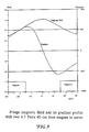
- FIGURE 2 A graph of the magnetic field along the z-axis (the bore center line), of magnet 100 is plotted in FIGURE 2.
- the gradient associated with this magnetic field is also plotted.
- truly homogenous static magnetic fields only exist in the center portion of the bore.
- the inhomogeneities within plus or minus 20 centimeters of the magnet center have sufficiently small built-in gradient that they might be controlled by conventionally configured magnetic gradient coils robustly constructed to handle larger currents and fields (and driven by similar robustly designed coil driving circuits capable of handling higher current levels required to off-set the inherent built-in gradients of the fringe fields).
- imaging techniques that are otherwise similar to conventional MRI (e.g., except for increased gradient fields, especially in the x and y dimensions and increased bandwidth RF nutation pulses).
- suitably restricting the image volume may provide yet another way of imaging in a substantially non-uniform or inhomogenous static field while requiring magnetic gradient pulses of somewhat lower magnitudes (e.g., to counteract the relatively weaker range of gradients encountered in a smaller volume).
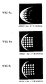
- FIGURES 3A, 3B and 3C illustrate possible fringe field imaging with currently available magnets. These simulated images are based on use of an assumed 4.7 Tesla imaging magnet of 40 centimeter bore diameter (which is close to those commercially available, e.g., Oxford type 200/400). The simulated images depicted at FIGURES 3A, 3B and 3C are respectively associated with three different off-set positions along the z-axis from the magnet center. In the image simulation, different magnitudes of gradient pulses were assumed. For example, for an off-set of 5 centimeters (FIGURE 3A), the intensity of simulated magnetic gradient pulses during the imaging sequence was 20 Gauss per centimeter.
- FIGURES 3A-3C are axial "slices" and distortions in the assumed read gradient direction (the x-dimension as shown), graphically demonstrate the effect of increasing field inhomogeneity and the inherent intense "built-in” gradients associated with such inhomogeneities.
- FIGURES 4-6 depict another exemplary embodiment wherein fringe fields outside the magnetic bore are utilized for the image volume. Similar reference numerals are used to depict similar parts in FIGURE 4.
- FIGURE 4 also depicts a 40 centimeter bore
- the most interesting and attractive approaches to truly high intensity fringe field MRI and spectroscopy may be the use of single even smaller bore magnets (e.g., 14 Tesla, 10 cm bore).
- Using the fringe field at the bore entrance such that a small image volume in that region can be created without physically inserting the whole body into the magnet bore (or even any part of it) would eliminate the necessity of making the magnet bores sufficiently large to accommodate the size of objects to be imaged (e.g., which is the current commercial design philosophy of today's whole body NMR scanners having a one meter bore diameter).
- the actual static field strength does of course decrease as a function of increasing distance with respect to the bore entrance.
- the expected field inhomogeneities can also be expected to increase outside the magnet bore.
- FIGURE 4 illustrates an image volume 110 located in the fringe field pattern 104 formed by the small bore single magnet 100.
- the static field strength at a distance of approximately 15 centimeters from the bore entrance is still at least about 70% of the maximum central field intensity (e.g., see the magnetic field plots of FIGURE 5).
- a still ultra-intense static magnetic field can be provided outside the bore of even a single magnet 100.
- the inherent "built-in” static gradient field is plotted as a function of distance from the center of the magnet along the z-axis (i.e., along the bore center line). As illustrated, at a distance of 50 centimeters away from the entrance, although the static magnetic field intensity is still very high (e.g, 70% of its maximum), the inherent or "built-in” static magnetic gradient can be as much as 1,000 Gauss per centimeter. Since conventional magnetic gradient field coils are designed to generate gradients of typically less than 2 Gauss per centimeter, this is well beyond anything that could be managed by conventional MRI spectroscopy. Perhaps the most difficult part of imaging in such intense fringe fields is accounting for the inhomogeneity in the form of built-in gradient fields, especially along the z-axis direction.
- the built-in static gradients are so enormous that they will also require extremely robust x and y gradient field coils and coil drivers.
- One way to circumvent this problem area is to select a small image volume with a relatively thick slice in the z-axis dimension (preselecting) and to then perform high resolution three-dimensional imaging within that sub-volume.
- the strong built-in gradient by using suitable x-y gradients, the resulting image would be a small 2-D high resolution image e.g., 2 cm x 2 cm x 0.1 mm (thickness).
- FIGURES 6A-6C depict a simulation of small volume imaging within the outside fringe field of a single small bore magnet.
- the axial area depicted is 2 centimeters by 2 centimeters (in the x and y dimensions) located at a distance 10 centimeters away from one end of the magnet.
- the static field strength is still about 75% of its maximum, the built-in gradients are extremely strong and on the order of approximately 1,000 gauss per centimeter.
- FIGURE 6A gradient pulses of 10 Gauss per centimeter
- FIGURE 6B using gradient pulses of 20 Gauss per centimeter
- FIGURE 6C using gradient pulses of 30 Gauss per centimeter
- FIGURES 7-9 depict another embodiment in which the image volume 110 is located between the spaced-apart ends of a pair of magnets 100. Again, similar reference numerals are used to depict similar parts in FIGURE 7.
- FIGURES 9A, 9B and 9C depict simulated images taken near the center of the gap between the two magnets of FIGURE 7 but using several different intensities of pulsed magnetic gradient fields during the imaging procedure.
- FIGURE 9A depicts an image taken with zero off-set and a magnetic gradient pulse strength of 10 gauss per centimeter.
- FIGURE 9B depicts a better image even at 2 centimeters off-set from the center with a considerably stronger gradient pulse of 20 Gauss per centimeter.
- FIGURE 9C is also located at a 2 centimeter off-set but with a somewhat stronger magnetic gradient pulse intensity of 30 Gauss per centimeter.
- RF coil configurations for fringe field MRI are not depicted in the drawings because conventional RF coil arrangement are believed suitable.
- the usual circular cage type of RF coil e.g., saddle coils, ring resonators, simple solenoidal coils, etc.
- the conventional ring resonator may be used for fringe field MRI inside a single magnet bore.
- fringe field MRI outside the bore of a single magnet and for fringe field MRI in the gap between the ends of two magnets
- any form of surface RF coil may also be used for fringe field MRI as in conventional MRI.
- Gradient coil design is always an important design consideration for MRI.
- the same basic gradient coil configurations per se are believed to be useful in fringe field MRI for generating relatively uniform, symmetric and sufficiently strong gradient fields.
- the size of conductors, numbers of turns, etc. may have to be adjusted so as to generate the relatively stronger required magnetic gradient pulses.
- the gradient current drivers will have to be made more robust so as to generate required higher levels of currents.
- asymmetric gradient fields are desired (e.g., for the one magnet embodiments utilizing fringe fields outside the bore) an asymmetric version of otherwise conventional gradient coils can be utilized.
- FIGURE 10(A) depicts a symmetric gradient coil configuration suitable for use with the FIGURE 1 embodiment involving gradient coil configurations substantially identical to conventional MRI systems utilizing horizontal magnet bores.
- two split Golay coil sets are utilized for x and y gradients (only the x-gradient coil being explicitly depicted so as to reduce drawing clutter).
- the usual z-axis gradient coils are also depicted in FIGURE 10(A).
- FIGURE 10(B) depicts an asymmetric gradient coil configuration suitable for use with the FIGURE 4 single magnet embodiment.
- an asymmetrical single gradient coil configuration is used for both the x and y gradients while a symmetric z-gradient coil set is utilized with respect to the image volume.
- asymmetric gradient fields would result (to complement the asymmetric static gradient fields) and thus a suitable adjustment for optimized, linear, symmetrical, composite gradient field formulations is preferred.
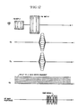
- FIGURE 10(C) depicts a symmetrical gradient coil configuration suitable for use with the FIGURE 7 embodiment.
- the gradient coils (again only the x-gradient coil is explicitly depicted so as to avoid unnecessary drawing clutter with the identical y-axis gradient coil rotated by 90° relative to that of the x-axis gradient coil) require increased intensity gradients so as to partially compensate for inhomogeneities within the image volume located in gap between the ends of the two magnets.
- FIGURE 11(A) depicts a pulse sequence for localized chunk 3-D imaging utilizing the built-in z gradient for volume selection as well as readout, without additional Z directional gradient fringe field imaging.
- This is a sequence known as a curved chunk 3-D technique.
- the proposed imaging pulse sequence actively utilizes the built-in gradient field for volume selection without additional z directional gradient. Again, the built-in gradient will be used for the readout gradient.
- the total measurement time can be reduced considerably. In order to select a sufficiently large volume under a strong built-in gradient, large RF bandwidth is usually required, however.
- the FM modulated RF signal in time domain and its corresponding spectrum are shown in FIGURES 13 and 14 respectively. Since the bandwidth of the FM pulse is given by 4 ⁇ T, the bandwidth can easily be controlled by either changing sweep rate ⁇ or window width 2T without changing the amplitude or peak power of the pulse.
- FIGURES 15A, 15B and 15C A set of simulation images with chunk-3D technique shown in FIGURE 12 is given in FIGURES 15A, 15B and 15C.
- the built-in gradient is used for slice selection as well as readout gradient.
- three sagittal images (readout - z direction) are obtained at offsets of 20 cm, 25 cm, and 35 cm. Due to the improved linearity of the built-in gradient, images reconstructed at larger offset show less image distortion, although the strength of the built-in gradient is proportionally increased.
- the requirement of wider band RF pulse is alleviated by the introduction of frequency modulated (FM) RF pulse.
- FM frequency modulated
- the first fringe field human image was obtained and is shown in FIGURE 16.
- the width of the FM RF pulse was 5 msec with a frequency sweep of 40 KHz.
- the image matrix was 64 x 64, and the scan time was 30 minutes. This shows that fringe field imaging can be performed under extremely inhomogeneous fields or built-in gradients that typically will be part of a fringe field MRI system.
Landscapes
- Physics & Mathematics (AREA)
- Condensed Matter Physics & Semiconductors (AREA)
- General Physics & Mathematics (AREA)
- Magnetic Resonance Imaging Apparatus (AREA)
Applications Claiming Priority (2)
| Application Number | Priority Date | Filing Date | Title |
|---|---|---|---|
| US354990 | 1989-05-22 | ||
| US07/354,990 US5023554A (en) | 1989-05-22 | 1989-05-22 | Fringe field MRI |
Publications (2)
| Publication Number | Publication Date |
|---|---|
| EP0399789A2 true EP0399789A2 (fr) | 1990-11-28 |
| EP0399789A3 EP0399789A3 (fr) | 1991-08-14 |
Family
ID=23395797
Family Applications (1)
| Application Number | Title | Priority Date | Filing Date |
|---|---|---|---|
| EP19900305557 Ceased EP0399789A3 (fr) | 1989-05-22 | 1990-05-22 | Structure de champ marginal pour l'imagerie à résonance magnétique |
Country Status (4)
| Country | Link |
|---|---|
| US (1) | US5023554A (fr) |
| EP (1) | EP0399789A3 (fr) |
| JP (1) | JPH03218732A (fr) |
| CA (1) | CA2017275A1 (fr) |
Cited By (19)
| Publication number | Priority date | Publication date | Assignee | Title |
|---|---|---|---|---|
| WO1991012538A1 (fr) * | 1990-02-08 | 1991-08-22 | Oxford Instruments Limited | Ensemble de generation de champ magnetique |
| GB2253909A (en) * | 1990-12-12 | 1992-09-23 | Picker Int Inc | Coil arrangements in nuclear magnetic resonance apparatus |
| DE4142263A1 (de) * | 1991-12-20 | 1993-06-24 | Bruker Analytische Messtechnik | Gradientenspulensystem |
| US5278504A (en) * | 1989-06-16 | 1994-01-11 | Picker International, Inc. | Gradient coil with off center sweet spot for magnetic resonance imaging |
| WO1994011748A1 (fr) * | 1992-11-18 | 1994-05-26 | Oxford Instruments Plc | Ensemble generant un champ magnetique oscillant |
| EP0610012A1 (fr) * | 1993-02-01 | 1994-08-10 | Panacea Medical Laboratories | Système à positionnement commandable à distance pour l'imagerie par résonance magnétique |
| GB2282227A (en) * | 1993-09-20 | 1995-03-29 | Bruker Medizintech | MRI magnet for limb imaging |
| EP0658773A1 (fr) * | 1993-12-14 | 1995-06-21 | Panacea Medical Laboratories | Procédé pour maintenir la cohérence des données de codage pour un système à positionnement commandable à distance pour l'imagerie par résonance magnétique |
| WO1998043103A1 (fr) * | 1997-03-26 | 1998-10-01 | Btg International Limited | Appareil et procede d'imagerie par resonance magnetique |
| EP0893701A1 (fr) * | 1997-07-24 | 1999-01-27 | Panacea Medical Laboratories | Imagerie par résonance magnétique à spectre étalé |
| DE19855212A1 (de) * | 1998-11-30 | 2000-06-21 | Siemens Ag | Kernspintomographie-Anlage mit inhomogenem Grundfeldmagneten |
| EP1340093A1 (fr) * | 2000-11-06 | 2003-09-03 | Topspin Medical (Israel) Limited | Dispositif d'imagerie par resonance magnetique |
| WO2004029644A1 (fr) * | 2002-09-30 | 2004-04-08 | Oxford Instruments Plc | Assemblage d'aimant |
| WO2004091721A1 (fr) | 2003-04-15 | 2004-10-28 | Philips Intellectual Property & Standards Gmbh | Procede et appareil permettant d'agir sur des particules magnetiques |
| WO2006010955A1 (fr) * | 2004-07-30 | 2006-02-02 | Aberdeen University | Detection nmr dans le champ de franges non homogenes d'un aimant |
| WO2007144890A1 (fr) * | 2006-06-15 | 2007-12-21 | Technion Research & Development Foundation Ltd. | Sonde et système pour l'imagerie par spin-résonance électronique |
| WO2008065389A1 (fr) * | 2006-11-28 | 2008-06-05 | Plant Bioscience Limited | Appareil de balayage d'imagerie par résonance magnétique avec champ magnétique radialement non-homogène |
| EP1593342B1 (fr) * | 2003-02-10 | 2011-12-14 | Hitachi Metals, Ltd. | Dispositif produisant un champ magnetique |
| WO2021183484A1 (fr) * | 2020-03-09 | 2021-09-16 | Promaxo, Inc. | Codage de phase par balayage de fréquence pulsé pour l'imagerie par résonance magnétique dans des champs magnétiques non homogènes |
Families Citing this family (27)
| Publication number | Priority date | Publication date | Assignee | Title |
|---|---|---|---|---|
| US5300887A (en) * | 1992-04-27 | 1994-04-05 | Albert Macovski | Pulsed field MRI system with spatial selection |
| US5357958A (en) * | 1993-03-18 | 1994-10-25 | The Regents Of The University Of California | Interventional MRI system and RF coils therefore |
| US5517118A (en) * | 1994-04-25 | 1996-05-14 | Panacea Medical Laboratories | Subslicing for remotely positioned MRI |
| US5914599A (en) * | 1995-08-18 | 1999-06-22 | National Research Council Of Canada | Compensation for inhomogeneity of the field generated by the RF coil in a nuclear magnetic resonance system |
| US5708362A (en) * | 1995-11-16 | 1998-01-13 | Siemens Aktiengesellschaft | Magnet arrangement for a diagnostic magnetic resonance apparatus |
| ATE419789T1 (de) | 1997-05-23 | 2009-01-15 | Prorhythm Inc | Wegwerfbarer fokussierender ultraschallapplikator hoher intensität |
| US6377836B1 (en) | 1999-02-17 | 2002-04-23 | Toshiba America Mri, Inc. | RF coil array for vertical field MRI |
| US6489872B1 (en) | 1999-05-06 | 2002-12-03 | New Mexico Resonance | Unilateral magnet having a remote uniform field region for nuclear magnetic resonance |
| JP3236274B2 (ja) * | 1999-06-24 | 2001-12-10 | ジーイー横河メディカルシステム株式会社 | 選択励起装置および磁気共鳴撮像装置 |
| GB2357149A (en) | 1999-12-08 | 2001-06-13 | Topspin Medical | MRI using non-homogeneous static field |
| US6462544B1 (en) | 2000-10-24 | 2002-10-08 | General Electric Company | Magnetic resonance imaging apparatus |
| US20040260790A1 (en) * | 2000-12-21 | 2004-12-23 | Ge Medical System Global Technology Company, Llc | Method and apparatus for remote or collaborative control of an imaging system |
| US6570383B1 (en) | 2000-12-27 | 2003-05-27 | Ge Medical Systems Global Technology Company, Llc | Method and apparatus for a pulse sequence for magnetic resonance imaging in an inhomogeneous magnetic field |
| JP3878429B2 (ja) * | 2001-04-05 | 2007-02-07 | ジーイー・メディカル・システムズ・グローバル・テクノロジー・カンパニー・エルエルシー | Mri装置 |
| US6738501B2 (en) * | 2001-04-13 | 2004-05-18 | Ge Medical Systems Global Technology Co., Llc | Adaptive data differentiation and selection from multi-coil receiver to reduce artifacts in reconstruction |
| WO2005047916A1 (fr) * | 2003-11-13 | 2005-05-26 | Parra-Robles Juan M | Procede et dispositif pour la compensation passive du champ de franges d'un aimant supraconducteur |
| WO2005067392A2 (fr) * | 2004-01-20 | 2005-07-28 | Topspin Medical (Israel) Ltd. | Sonde irm destinee a l'imagerie de la prostate |
| US20060084861A1 (en) * | 2004-10-18 | 2006-04-20 | Topspin Medical (Isreal) Ltd. | Magnet and coil configurations for MRI probes |
| US20060084866A1 (en) * | 2004-10-18 | 2006-04-20 | Gadi Lewkonya | Expanding imaging probe |
| US7309986B2 (en) * | 2005-03-21 | 2007-12-18 | The Trustees Of The University Of Pennsylvania | Methods and apparatus for magnetic resonance imaging in inhomogeneous fields |
| WO2007061438A2 (fr) * | 2005-11-16 | 2007-05-31 | The Trustees Of The University Of Pennsylvania | Imagerie en coupe oblique a champs non homogenes |
| US20070238971A1 (en) * | 2006-01-04 | 2007-10-11 | California Institute Of Technology | Apparatus and method for two-and three-dimensional magnetic resonance imaging using ferromagnetic spheres |
| US7667462B2 (en) * | 2006-12-22 | 2010-02-23 | Schlumberger Technology Corporation | Nuclear magnetic resonance module |
| CN103260701B (zh) * | 2010-12-16 | 2017-10-31 | 皇家飞利浦电子股份有限公司 | 采用大腔膛的核及磁共振成像或者大腔膛的ct及磁共振成像的辐射治疗规划和跟踪系统 |
| WO2014015421A1 (fr) | 2012-07-27 | 2014-01-30 | University Health Network | Système de radiothérapie intégrant une source de rayonnement avec un appareil d'imagerie par résonance magnétique avec des composants d'aimant mobiles |
| CN115407252A (zh) | 2016-06-22 | 2022-11-29 | 优瑞技术公司 | 低场强磁共振成像 |
| US11209509B2 (en) * | 2018-05-16 | 2021-12-28 | Viewray Technologies, Inc. | Resistive electromagnet systems and methods |
Family Cites Families (29)
| Publication number | Priority date | Publication date | Assignee | Title |
|---|---|---|---|---|
| GB2070254B (en) * | 1980-01-21 | 1984-10-17 | Oxford Instr Group Ltd | Nuclear magnetic resonance apparatus and methods |
| US4374360A (en) * | 1980-05-29 | 1983-02-15 | Sepponen Raimo E | NMR Diagnosis apparatus |
| DE3209810A1 (de) * | 1982-03-18 | 1983-10-13 | Bruker Medizintechnik Gmbh, 7512 Rheinstetten | Verfahren zum messen der magnetischen kernresonanz fuer die nmr-tomographie |
| US4486709A (en) * | 1982-11-22 | 1984-12-04 | Bendall Max R | Depth and refocusing pulses for use with inhomogeneous radiofrequency coils in nuclear magnetic resonance spectroscopy |
| US4742303A (en) * | 1982-11-22 | 1988-05-03 | Bendall Max R | Depth and refocusing pulses for use with inhomogeneous radiofrequency coils in nuclear magnetic resonance spectroscopy |
| EP0121367B1 (fr) * | 1983-03-30 | 1990-05-23 | Picker International Limited | Appareil pour la production d'images par résonance magnétique nucléaire |
| GB8329196D0 (en) * | 1983-11-02 | 1983-12-07 | Bydder G M | Nuclear magnetic resonance apparatus |
| US4591789A (en) * | 1983-12-23 | 1986-05-27 | General Electric Company | Method for correcting image distortion due to gradient nonuniformity |
| US4692705A (en) * | 1983-12-23 | 1987-09-08 | General Electric Company | Radio frequency field coil for NMR |
| JPS60189905A (ja) * | 1984-03-09 | 1985-09-27 | Mitsubishi Electric Corp | 高均一磁界発生装置 |
| US4721914A (en) * | 1984-05-01 | 1988-01-26 | The United States Of America As Represented By The United States Department Of Energy | Apparatus for unilateral generation of a homogeneous magnetic field |
| US4595899A (en) * | 1984-07-06 | 1986-06-17 | The Board Of Trustees Of The Leland Stanford Junior University | Magnetic structure for NMR applications and the like |
| US4797617A (en) * | 1984-08-16 | 1989-01-10 | Picker International, Inc. | Nuclear magnetic resonance radio frequency antenna |
| US4634980A (en) * | 1984-08-16 | 1987-01-06 | Picker International, Inc. | Nuclear magnetic resonance radio frequency antenna |
| US4740751A (en) * | 1984-08-16 | 1988-04-26 | Picker International, Inc. | Whole body MRI resonator |
| FR2574551B1 (fr) * | 1984-12-12 | 1986-12-26 | Commissariat Energie Atomique | Procede de generation et de traitement de signaux pour l'obtention par resonance magnetique nucleaire d'une image exempte de distorsions a partir d'un champ de polarisation inhomogene |
| US4638252A (en) * | 1984-12-21 | 1987-01-20 | General Electric Company | Circuit for detecting RF coil assembly position in an MR scanner |
| JPS61115958U (fr) * | 1984-12-30 | 1986-07-22 | ||
| US4617936A (en) * | 1985-08-08 | 1986-10-21 | North American Philips Corporation | Flexible surface coil for magnetic resonance imaging |
| JPH0620435B2 (ja) * | 1985-09-25 | 1994-03-23 | 株式会社日立メディコ | 核磁気共鳴イメージング装置 |
| US4680551A (en) * | 1985-10-07 | 1987-07-14 | General Electric Company | Method for homogenizing a static magnetic field over an arbitrary volume |
| US4684893A (en) * | 1985-12-23 | 1987-08-04 | Kabushiki Kaisha Toshiba | Field gradient correction apparatus for compensating static field inhomogeneities in NMR imaging system |
| US4703270A (en) * | 1986-04-18 | 1987-10-27 | The University Of British Columbia | Zero quantum NMR imaging and spectroscopy in a low homogeneity magnetic field |
| US4707664A (en) * | 1986-06-25 | 1987-11-17 | The Regents Of The University Of California | QD MRI RE coil using non-homogeneous and non-uniform RF field distribution |
| US4714885A (en) * | 1986-08-04 | 1987-12-22 | Elscint Ltd. | Magnetic resonance imaging |
| US4777956A (en) * | 1986-08-06 | 1988-10-18 | Stanford University | NMR angiography system and method with immunity to inhomogeneity |
| GB8702951D0 (en) * | 1987-02-10 | 1987-03-18 | Surrey Medical Imaging Systems | Nmr imaging |
| US4733190A (en) * | 1987-03-16 | 1988-03-22 | Medical Advances, Inc. | NMR local coil with adjustable spacing |
| US4924198A (en) * | 1988-07-05 | 1990-05-08 | General Electric Company | Superconductive magnetic resonance magnet without cryogens |
-
1989
- 1989-05-22 US US07/354,990 patent/US5023554A/en not_active Expired - Fee Related
-
1990
- 1990-05-22 CA CA002017275A patent/CA2017275A1/fr not_active Abandoned
- 1990-05-22 JP JP2132405A patent/JPH03218732A/ja active Pending
- 1990-05-22 EP EP19900305557 patent/EP0399789A3/fr not_active Ceased
Cited By (36)
| Publication number | Priority date | Publication date | Assignee | Title |
|---|---|---|---|---|
| US5278504A (en) * | 1989-06-16 | 1994-01-11 | Picker International, Inc. | Gradient coil with off center sweet spot for magnetic resonance imaging |
| US5331282A (en) * | 1990-02-08 | 1994-07-19 | Oxford Instruments (Uk) Limited | Magnetic field generating assembly |
| WO1991012538A1 (fr) * | 1990-02-08 | 1991-08-22 | Oxford Instruments Limited | Ensemble de generation de champ magnetique |
| GB2253909A (en) * | 1990-12-12 | 1992-09-23 | Picker Int Inc | Coil arrangements in nuclear magnetic resonance apparatus |
| GB2253909B (en) * | 1990-12-12 | 1994-09-28 | Picker Int Inc | Coil arrangements in magnetic resonance apparatus |
| US5343148A (en) * | 1991-12-20 | 1994-08-30 | Bruker Analytische Messtechnik Gmbh | Gradient coil system |
| GB2262808B (en) * | 1991-12-20 | 1995-10-04 | Bruker Analytische Messtechnik | Gradient coil system |
| DE4142263A1 (de) * | 1991-12-20 | 1993-06-24 | Bruker Analytische Messtechnik | Gradientenspulensystem |
| GB2262808A (en) * | 1991-12-20 | 1993-06-30 | Bruker Analytische Messtechnik | Gradient coil system |
| WO1994011748A1 (fr) * | 1992-11-18 | 1994-05-26 | Oxford Instruments Plc | Ensemble generant un champ magnetique oscillant |
| US5680044A (en) * | 1992-11-18 | 1997-10-21 | Oxford Instruments Plc | Oscillating magnetic field generating assembly |
| EP0610012A1 (fr) * | 1993-02-01 | 1994-08-10 | Panacea Medical Laboratories | Système à positionnement commandable à distance pour l'imagerie par résonance magnétique |
| GB2282227A (en) * | 1993-09-20 | 1995-03-29 | Bruker Medizintech | MRI magnet for limb imaging |
| GB2282227B (en) * | 1993-09-20 | 1998-03-04 | Bruker Medizintech | Nuclear magnetic resonance tomography apparatus |
| EP0658773A1 (fr) * | 1993-12-14 | 1995-06-21 | Panacea Medical Laboratories | Procédé pour maintenir la cohérence des données de codage pour un système à positionnement commandable à distance pour l'imagerie par résonance magnétique |
| US5493225A (en) * | 1993-12-14 | 1996-02-20 | Panacea Medical Laboratories | Method for maintaining encoded coherence for remotely positioned MRI device |
| WO1998043103A1 (fr) * | 1997-03-26 | 1998-10-01 | Btg International Limited | Appareil et procede d'imagerie par resonance magnetique |
| EP1308743A1 (fr) * | 1997-07-24 | 2003-05-07 | Panacea Medical Laboratories | Imagerie par résonance magnétique à spectre étalé |
| EP0893701A1 (fr) * | 1997-07-24 | 1999-01-27 | Panacea Medical Laboratories | Imagerie par résonance magnétique à spectre étalé |
| DE19855212A1 (de) * | 1998-11-30 | 2000-06-21 | Siemens Ag | Kernspintomographie-Anlage mit inhomogenem Grundfeldmagneten |
| DE19855212C2 (de) * | 1998-11-30 | 2000-10-12 | Siemens Ag | Kernspintomographie-Anlage mit inhomogenem Grundfeldmagneten |
| US6297633B1 (en) | 1998-11-30 | 2001-10-02 | Siemens Aktiengesellschaft | Magnetic resonance tonography system with non-uniform basic field magnet |
| EP1340093A1 (fr) * | 2000-11-06 | 2003-09-03 | Topspin Medical (Israel) Limited | Dispositif d'imagerie par resonance magnetique |
| US7355499B2 (en) | 2002-09-30 | 2008-04-08 | Oxford Instruments Plc | Magnet assembly |
| WO2004029644A1 (fr) * | 2002-09-30 | 2004-04-08 | Oxford Instruments Plc | Assemblage d'aimant |
| EP1593342B1 (fr) * | 2003-02-10 | 2011-12-14 | Hitachi Metals, Ltd. | Dispositif produisant un champ magnetique |
| WO2004091721A1 (fr) | 2003-04-15 | 2004-10-28 | Philips Intellectual Property & Standards Gmbh | Procede et appareil permettant d'agir sur des particules magnetiques |
| US7758622B2 (en) | 2003-04-15 | 2010-07-20 | Koninklijke Philips Electronics N.V. | Method and apparatus for influencing magnetic particles |
| GB2431727A (en) * | 2004-07-30 | 2007-05-02 | Univ Aberdeen | NMR detection in the inhomogeneous fringe field of a magnet |
| GB2431727B (en) * | 2004-07-30 | 2008-10-22 | Univ Aberdeen | NMR detection in the inhomogeneous fringe field of a magnet |
| WO2006010955A1 (fr) * | 2004-07-30 | 2006-02-02 | Aberdeen University | Detection nmr dans le champ de franges non homogenes d'un aimant |
| WO2007144890A1 (fr) * | 2006-06-15 | 2007-12-21 | Technion Research & Development Foundation Ltd. | Sonde et système pour l'imagerie par spin-résonance électronique |
| US8067937B2 (en) | 2006-06-15 | 2011-11-29 | Technion Research & Development Foundation Ltd. | Probe and system for electron spin resonance imaging |
| WO2008065389A1 (fr) * | 2006-11-28 | 2008-06-05 | Plant Bioscience Limited | Appareil de balayage d'imagerie par résonance magnétique avec champ magnétique radialement non-homogène |
| WO2021183484A1 (fr) * | 2020-03-09 | 2021-09-16 | Promaxo, Inc. | Codage de phase par balayage de fréquence pulsé pour l'imagerie par résonance magnétique dans des champs magnétiques non homogènes |
| US12210079B2 (en) | 2020-03-09 | 2025-01-28 | Promaxo, Inc. | Phase encoding with frequency sweep pulses for magnetic resonance imaging in inhomogeneous magnetic fields |
Also Published As
| Publication number | Publication date |
|---|---|
| US5023554A (en) | 1991-06-11 |
| JPH03218732A (ja) | 1991-09-26 |
| EP0399789A3 (fr) | 1991-08-14 |
| CA2017275A1 (fr) | 1990-11-22 |
Similar Documents
| Publication | Publication Date | Title |
|---|---|---|
| US5023554A (en) | Fringe field MRI | |
| Posse et al. | Three-dimensional echo-planar MR spectroscopic imaging at short echo times in the human brain. | |
| Langlois et al. | MRI geometric distortion: a simple approach to correcting the effects of non‐linear gradient fields | |
| Blamire et al. | Dynamic shim updating: a new approach towards optimized whole brain shimming | |
| US6445182B1 (en) | Geometric distortion correction in magnetic resonance imaging | |
| Vlaardingerbroek et al. | Magnetic resonance imaging: theory and practice | |
| Ibrahim et al. | Dielectric resonances and B1 field inhomogeneity in UHFMRI: computational analysis and experimental findings | |
| Duyn et al. | Multisection proton MR spectroscopic imaging of the brain. | |
| Weavers et al. | Compact three‐tesla magnetic resonance imager with high‐performance gradients passes ACR image quality and acoustic noise tests | |
| EP0146873A2 (fr) | Procédé pour corriger la distorsion d'image due à la non-uniformité du gradient de champ magnétique | |
| Thomas et al. | High‐resolution fast spin echo imaging of the human brain at 4.7 T: implementation and sequence characteristics | |
| US20090253983A1 (en) | Image based measurement of contrast agents | |
| Liu et al. | Biopsy needle tip artifact in MR‐guided neurosurgery | |
| US5799653A (en) | Magnetic resonance imaging apparatus with decreased patient claustrophobia and increased access to patient | |
| Schmalbrock et al. | Optimization of submillimeter‐resolution MR imaging methods for the inner ear | |
| Cho et al. | New brain atlas—mapping the human brain in vivo with 7.0 T MRI and comparison with postmortem histology: will these images change modern medicine? | |
| Effmann et al. | Magnetic resonance microscopy of chick embryos in ovo | |
| Hillenbrand et al. | High-order MR shimming: a simulation study of the effectiveness of competing methods, using an established susceptibility model of the human head | |
| Lee et al. | Localized volume selection technique using an additional radial gradient coil | |
| US6570383B1 (en) | Method and apparatus for a pulse sequence for magnetic resonance imaging in an inhomogeneous magnetic field | |
| Makihara et al. | High-resolution MRI for human embryos with isotropic 10 μm resolution at 9.4 T | |
| Rudin | MR microscopy on rats in vivo at 4.7 T using surface coils | |
| Hennel et al. | Basics of magnetic resonance imaging | |
| Campbell et al. | Diffusion MRI acquisition for tractography: Diffusion encoding | |
| US20240345191A1 (en) | Integrated b0-shim coil configurations for mri b0 shimming in target tissues |
Legal Events
| Date | Code | Title | Description |
|---|---|---|---|
| PUAI | Public reference made under article 153(3) epc to a published international application that has entered the european phase |
Free format text: ORIGINAL CODE: 0009012 |
|
| AK | Designated contracting states |
Kind code of ref document: A2 Designated state(s): AT BE CH DE DK ES FR GB GR IT LI LU NL SE |
|
| PUAL | Search report despatched |
Free format text: ORIGINAL CODE: 0009013 |
|
| AK | Designated contracting states |
Kind code of ref document: A3 Designated state(s): AT BE CH DE DK ES FR GB GR IT LI LU NL SE |
|
| 17P | Request for examination filed |
Effective date: 19910912 |
|
| 17Q | First examination report despatched |
Effective date: 19931105 |
|
| STAA | Information on the status of an ep patent application or granted ep patent |
Free format text: STATUS: THE APPLICATION HAS BEEN REFUSED |
|
| 18R | Application refused |
Effective date: 19950830 |