EP0400085B1 - Ausziehbare sitzanordnung für fahrzeuge - Google Patents
Ausziehbare sitzanordnung für fahrzeuge Download PDFInfo
- Publication number
- EP0400085B1 EP0400085B1 EP89904142A EP89904142A EP0400085B1 EP 0400085 B1 EP0400085 B1 EP 0400085B1 EP 89904142 A EP89904142 A EP 89904142A EP 89904142 A EP89904142 A EP 89904142A EP 0400085 B1 EP0400085 B1 EP 0400085B1
- Authority
- EP
- European Patent Office
- Prior art keywords
- seat
- sections
- section
- arrangement
- extendable
- Prior art date
- Legal status (The legal status is an assumption and is not a legal conclusion. Google has not performed a legal analysis and makes no representation as to the accuracy of the status listed.)
- Expired
Links
- 230000006870 function Effects 0.000 description 2
- 230000004048 modification Effects 0.000 description 2
- 238000012986 modification Methods 0.000 description 2
- 230000000712 assembly Effects 0.000 description 1
- 238000000429 assembly Methods 0.000 description 1
- 230000000052 comparative effect Effects 0.000 description 1
- 230000015654 memory Effects 0.000 description 1
- 230000000284 resting effect Effects 0.000 description 1
- 239000007787 solid Substances 0.000 description 1
- 238000005728 strengthening Methods 0.000 description 1
Images



Classifications
-
- B—PERFORMING OPERATIONS; TRANSPORTING
- B60—VEHICLES IN GENERAL
- B60N—SEATS SPECIALLY ADAPTED FOR VEHICLES; VEHICLE PASSENGER ACCOMMODATION NOT OTHERWISE PROVIDED FOR
- B60N2/00—Seats specially adapted for vehicles; Arrangement or mounting of seats in vehicles
- B60N2/02—Seats specially adapted for vehicles; Arrangement or mounting of seats in vehicles the seat or part thereof being movable, e.g. adjustable
- B60N2/04—Seats specially adapted for vehicles; Arrangement or mounting of seats in vehicles the seat or part thereof being movable, e.g. adjustable the whole seat being movable
- B60N2/14—Seats specially adapted for vehicles; Arrangement or mounting of seats in vehicles the seat or part thereof being movable, e.g. adjustable the whole seat being movable rotatable, e.g. to permit easy access
- B60N2/143—Seats specially adapted for vehicles; Arrangement or mounting of seats in vehicles the seat or part thereof being movable, e.g. adjustable the whole seat being movable rotatable, e.g. to permit easy access taking a position opposite to the original one
Definitions
- This invention relates to an extendable seat arrangement for vehicles which enables a user, particularly an invalid, to enter and leave a vehicle with comparative ease and which occupies a smaller space in a vehicle than do previously proposed arrangements which provide similar facilities.
- the mechanism occupies an area of the floor of the vehicle which extends far beyond that which is normally occupied by the vehicle seat.
- the arrangement presently proposed occupies both a minimum of floor area and a minimum of volume.
- At least three telescopically extending interlocking sections are employed to carry a seat from the outside to the inside of the vehicle, thereby enabling the overall length of the sections when telescoped together within the vehicle to be kept to a minimum.
- the sections interlock in such a way that the depth of the assembly is kept small, giving a very low profile.
- the sections to be telescoped are curved, it would be possible to achieve a similar result by employing straight interlocking telescopic sections, all of which pivot about a single pivot point on the vehicle.
- the telescopic assembly does not protrude behind the area occupied by the car seat, and that the curved sections of the assembly when telescoped together extend over an arc which is no greater than 90° taken from the origin of the curve.
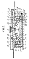
- FIG. 1 and 2 of the drawings there are shown a mounting plate 1 for a seat, a carriage 2 upon which the plate 1 is mounted and an interlocking assembly of curved sections 3, 4 and 5 which telescope together.
- a pivot arrangement for a seat is indicated generally at 6.
- the curved section 3 which is fixed relative to a vehicle, acts as a base for the assembly and is provided with a series of wheels or roller bearings 7 on the inside of its vertical walls 8.
- the curved section 4 is so formed that channels 9 are provided on the outside of its vertical walls 11.
- the wheels or roller bearings 7 run in the respective channels 9 with the upper edges 12 of the channels 9 resting on the wheels or roller bearings 7.
- the curved section 5 has channels 14 on the outside of its vertical walls 15 and wheels or roller bearings 16 which are on the inside of the respective walls 11 run in the channels 14.
- the upper edges 17 of the channels 14 rest on the wheels on roller bearings 16.
- the wheels 19 Depending from the carriage 2, there are four support wheels 19 which are rotatable on shafts 20.
- the wheels 19 run in respective grooves 21 in the inner surface of the curved section 5.
- the wheels 19 have tapered upper edges 22 which run on the undercut faces 23 of the respective grooves 21 and tapered sides 24 which run on the other faces 25 of the grooves 19.
- the interlocking assembly provided by the engagement of the wheels 19 in the grooves 21, the wheels or roller bearings 16 in the channels 14 and the wheels or roller bearings 7 in the channels 9, prevents the carriage 2 and thus any seat mounted on the carriage 2 from tipping sideways about the assembly of curved sections 3 to 5.
- the curved section 4, which carries the section 5 upon which the seat mounting plate 1 and the carriage 2 are mounted, may be extended through an arc of about 30° about the point 25a until the position indicated by the dash-dot lines 26 is reached, the section 4 running over the wheels 7.
- the section 5 carrying the plate 1 and the carriage 2 may then be extended from the section 4 through a further 60° of arc until the position indicated by the dash-dot lines 27 is reached.
- Fig. 3 in which similar parts are indicated by the same reference numerals as those used with reference to Fig. 1, the sections 3, 4 and 5 overlap and the overall width of each of the sections 4 and 5 is the same.
- One edge 30 of each of the sections 4 and 5 is toothed for at least a part of its length.
- the toothed edges 30 are better seen when the sections 4 and 5 are in the extended positions 26 and 27 respectively.
- the toothed edges 30 cooperate with a gear wheel 31 which is driven by a motor 32.
- the motor 32 is arranged to rotate the gear wheel 31 in one direction to drive firstly the section 5 into the position 26 and subsequently the section 4 and 5 together so that the extended section 5 moves to the position 27 and the section 4 is moved to the position 26.
- a second electric motor which is mounted on the carriage 2 and which drives a gear wheel 34.
- the gear wheel 34 is arranged to engage a toothed edge 35 on an inner portion of the section 5 and the motor 33 may be energised to rotate the gear wheel 34 in either direction and thus to move the carriage 2 and the plate 1 in either direction along the length of the curved section 5.
- a further electric motor 37 is mounted on the plate 1.
- the motor 37 drives a gear wheel 38.
- the gear wheel 38 engages a toothed edge 39 on the carriage 2, and by driving the motor 37 it is possible to cause the plate 1 to be rotated about the carriage 2 as the gear wheel 38 engages the toothed edge 39.
- the plate 1 may be rotated in either the clockwise or anti-clockwise direction.
- the electric motor drive means are merely illustrative of the drive means that may be used to power the assembly.
- FIG. 4 there are illustrated ways of powering other functions of a seat arrangement employing the present invention.
- the plate 1 on which the seat is carried is formed with inverted troughs 41, 42 and 43. These troughs form the basic supports for the back and sides of a seat, and beneath the plate 1 there is a corresponding base plate 44 which is rotatable with the plate 1 about the carriage 2.
- the plate 1 is movable vertically relative to the base plate 44.
- the power to move the plate 1 vertically is provided by a motor, shown diagrammatically at 45, which drives a scissors lift indicated at 46 housed in inverted trough 43 via a drive shaft 47 and gearing 48.
- a similarly driven scissors arrangement is provided in inverted trough 42.
- the plate 1 is driven backwards and forwards, as indicated by arrow 50 relative to the base plate 44 by means of a motor 51 which is housed in inverted trough 41 and which drives a lead screw 52 located in brackets 53 and 54 on the plate 1.
- a block 55 which is fixed to the base plate 44 via a slot in the plate 1, has a threaded hole which runs on the lead screw 52 in order to provide the relative fore and aft movement between the plate 1 and the base plate 44. It will be understood that the arrangements described are diagrammatic and that there are many ways of implementing the movements described. It will be understood, for example, that bearing arrangements are provided between the scissors lifts 46 and the troughs 42 and 43 in order to enable the fore and aft movement 50 to be made smoothly.
- FIG. 5 broken lines 60 indicate the outline of a seat and, as with Figs. 3 and 4, similar parts are referenced with the same numerals as were used in referring to Figs. 1 and 2.
- the pivot arrangement 6, which is shown in Fig. 5 also incorporates a pin 61, which may be moved into or out of a hole in the member 5 and thereby lock or release the assembly of the carriage 2 and the seat mounting plate 1 to or from the section 5.
- the pin 61 is operated by an electrically operated solenoid
- the pivot 6 incorporates a mechanically operated pin to lock or release the assembly.
- FIG 66 there is shown an assembly of sections 3, 4 and 5 corresponding to that described with reference to Figs. 1 and 2, in which the upper parts 67, 68 and 69 nest one within the other, while at 71 there is shown an assembly corresponding to that of Fig. 3, in which the upper parts 72, 73 and 74 overlap one another and the drive motor 32 with its gear wheel 31 engaging the toothed edges 30 of the sections 3, 4 and 5 can be seen.
- the part 72 has a strengthening member 75 and that the cross sections of the bases of the sections 3, 4 and 5 are, in the assembly 71, dished in order to increase their strength.
- the sections 3, 4 and 5 may, for example, be straight and means may be provided in the vehicle, with such a modification, for the section 3 to be rotated with respect to the vehicle in order to enable a seat to be conveyed in and out of the vehicle.
- roller bearings may be used, for example ball races or solid bearings. It is, of course, possible to employ other combinations of extendable section and to employ different lengths of overlap between the sections from those shown.
- the curved section 4 which is shown in the arrangement of Fig. 1 extends through an arc of about 30°, and the section 5 extends over 60°, they could each extend over 45°
- the seat which is carried by the telescopically interlocking sections may be of any suitable type, for example it may be a wheel chair, or a normal-looking vehicle seat.
- the interlocking section which carries the seat is shown fitted in a dished manner within the other two sections, it would be possible, for example, for the sections 3, 4, and 5 to be inverted, compared to the arrangements shown in Fig. 5, and for the section carrying the seat to be the outer one of the interlocking sections, with a suitable redesigning of the bearing arrangements.
Landscapes
- Engineering & Computer Science (AREA)
- Aviation & Aerospace Engineering (AREA)
- Transportation (AREA)
- Mechanical Engineering (AREA)
- Seats For Vehicles (AREA)
Claims (8)
- Ausziehbare Sitzanordnung zur Verwendung beim Bewegen eines Sitzes in einen beengten Raum und aus diesem heraus, enthaltend eine Vielzahl teleskopisch verlaufender, miteinander verschachtelter ineinandergreifender Abschnitte (3, 4, 5), von denen ein Abschnitt (5) Mittel (1) zum Tragen eines Sitzes enthält, dadurch gekennzeichnet, daß die teleskopisch verlaufenden ineinandergreifenden Abschnitte (3, 4, 5) gebogen sind.
- Anordnung nach Anspruch 1, enthaltend elektromechanische Mittel (31, 32, 34, 34, 37, 38), die derart angeordnet sind, daß sie die Abschnitte in ihre ausgezogene und ihre eingeschobene Position antreiben.
- Anordnung nach Anspruch 2, bei der ein Abschnitt Zähne (30) längs einer Kante aufweist, und die einen Elektromotor (32) und ein von dem Motor angetriebenes Zahnrad (31) aufweist, das derart angeordnet ist, daß es in die Zähne (30) an der Kante des Abschnitts (5) eingreift, um den entsprechenden Abschnitt (5) in seine ausgefahrene und eingeschobene Position anzutreiben.
- Anordnung nach einem der vorhergehenden Ansprüche, enthaltend zwischen den Abschnitten (3, 4, 5) angeordnete Lagermittel (7, 16), die Mittel (9, 14) zum gegenseitigen Verriegeln der Abschnitte (3, 4, 5) vorsehen.
- Ausziehbare Sitzanordnung nach einem der vorhergehenden Ansprüche, bei der die ineinandergreifenden Abschnitte (3, 4, 5) einen im wesentlichen muldenförmigen Querschnitt aufweisen und dadurch die Verschachtelung der Abschnitte ineinander erleichtern.
- Ausziehbare Sitzanordnung nach einem der vorhergehenden Ansprüche, enthaltend elektromechanische Mittel (37, 38) zum Rotieren eines Sitzes um einen Punkt auf einem den Sitz tragenden Abschnitt (5).
- Ausziehbare Sitzanordnung nach einem der vorhergehenden Ansprüche, enthaltend elektromechanische Mittel (45, 46) zum Anheben und Absenken eines Sitzes gegenüber einem den Sitz tragenden Abschnitt (5).
- Ausziehbare Sitzanordnung nach einem der vorhergehenden Ansprüche, enthaltend elektromechanische Mittel (51, 52) zum Bewegen eines Sitzes in einer zu der Ebene der ineinandergreifenden Abschnitte (3, 4, 5) im wesentlichen parallelen Ebene.
Priority Applications (1)
| Application Number | Priority Date | Filing Date | Title |
|---|---|---|---|
| AT89904142T ATE81082T1 (de) | 1988-03-25 | 1989-03-23 | Ausziehbare sitzanordnung fuer fahrzeuge. |
Applications Claiming Priority (2)
| Application Number | Priority Date | Filing Date | Title |
|---|---|---|---|
| GB8807142 | 1988-03-25 | ||
| GB888807142A GB8807142D0 (en) | 1988-03-25 | 1988-03-25 | Extendable seat arrangement for vehicles |
Publications (2)
| Publication Number | Publication Date |
|---|---|
| EP0400085A1 EP0400085A1 (de) | 1990-12-05 |
| EP0400085B1 true EP0400085B1 (de) | 1992-09-30 |
Family
ID=10634108
Family Applications (1)
| Application Number | Title | Priority Date | Filing Date |
|---|---|---|---|
| EP89904142A Expired EP0400085B1 (de) | 1988-03-25 | 1989-03-23 | Ausziehbare sitzanordnung für fahrzeuge |
Country Status (7)
| Country | Link |
|---|---|
| US (1) | US5195712A (de) |
| EP (1) | EP0400085B1 (de) |
| JP (1) | JPH03503392A (de) |
| AU (1) | AU619003B2 (de) |
| CA (1) | CA1300477C (de) |
| GB (2) | GB8807142D0 (de) |
| WO (1) | WO1989009145A1 (de) |
Cited By (2)
| Publication number | Priority date | Publication date | Assignee | Title |
|---|---|---|---|---|
| DE10120769B4 (de) * | 2001-04-27 | 2012-08-16 | GM Global Technology Operations LLC (n. d. Ges. d. Staates Delaware) | Schwenksitzanordnung für ein Fahrzeug mit einem Schwenkantrieb |
| DE102019115602A1 (de) * | 2019-06-07 | 2020-12-10 | Faurecia Autositze Gmbh | Drehvorrichtung für einen Fahrzeugsitz sowie Fahrzeugsitz |
Families Citing this family (7)
| Publication number | Priority date | Publication date | Assignee | Title |
|---|---|---|---|---|
| GB2251374A (en) * | 1990-12-18 | 1992-07-08 | Elap Eng Ltd | Displaceable vehicle seats |
| FR2676690B1 (fr) * | 1991-05-23 | 1993-09-03 | Faure Bertrand Automobile | Plateau formant base tournante pour siege de vehicule. |
| US5482243A (en) * | 1994-02-07 | 1996-01-09 | General Motors Corporation | Seat adjuster slide arrangement |
| US5580023A (en) * | 1994-08-08 | 1996-12-03 | R. H. Burton Company | Integrated ophthalmic examination chair and positioning system |
| US5520363A (en) * | 1994-08-08 | 1996-05-28 | R. H. Burton Company | Ophthalmic examination chair positioning system |
| FR2757463B1 (fr) * | 1996-12-23 | 1999-03-05 | Peugeot | Siege pour vehicule automobile |
| EP1454764B1 (de) * | 2003-03-04 | 2010-07-28 | Invacare AG | Vorderradträger für einen Rollstuhl |
Family Cites Families (15)
| Publication number | Priority date | Publication date | Assignee | Title |
|---|---|---|---|---|
| US1741784A (en) * | 1927-02-23 | 1929-12-31 | Milwaukee Electric Railway & L | Car-seat-reversing mechanism |
| US2472349A (en) * | 1945-06-21 | 1949-06-07 | Heywood Wakefield Co | Reversible seat |
| US2446906A (en) * | 1946-10-29 | 1948-08-10 | Coach & Car Equipment Corp | Reversible seat |
| US3043622A (en) * | 1959-10-26 | 1962-07-10 | Milner Samuel | Movable seat |
| GB1592542A (en) * | 1978-03-13 | 1981-07-08 | Transportation Design & Techn | Wheelchair lift |
| FR2429011A1 (fr) * | 1978-06-22 | 1980-01-18 | Betton Rene | Dispositif pour transborder un handicape physique de son fauteuil roulant a un vehicule automobile et reciproquement |
| GB2071585B (en) * | 1980-03-19 | 1983-10-19 | Gowrings Ltd | Vehicle entry system for invalids and a wheel chair suitable for use with the entry system |
| US4544202A (en) * | 1982-01-29 | 1985-10-01 | Keaton Tanya L | Semiautomatically actuated rotable lounge chair |
| JPS5914525A (ja) * | 1982-07-14 | 1984-01-25 | Nissan Motor Co Ltd | 回転座席における摺動ロツク機構 |
| FR2552036B1 (fr) * | 1983-09-15 | 1988-04-29 | Gateau Eugene | Vehicule perfectionne, pouvant etre utilise notamment par une personne handicapee |
| GB8411632D0 (en) * | 1984-05-08 | 1984-06-13 | Bailey R M | Swivellable seat for motor vehicles |
| JPS6157047U (de) * | 1984-09-21 | 1986-04-17 | ||
| SE8501212D0 (sv) * | 1985-03-12 | 1985-03-12 | Uponor Ab | Sett vid tillverkning av vermeisolerat ror |
| GB2184005B (en) * | 1985-09-18 | 1990-05-23 | Goodall Melvyn John | Improved vehicle seat |
| US4784434A (en) * | 1987-04-24 | 1988-11-15 | Tachi-S Co. | Vehicle seat with suspension device |
-
1988
- 1988-03-25 GB GB888807142A patent/GB8807142D0/en active Pending
-
1989
- 1989-03-23 EP EP89904142A patent/EP0400085B1/de not_active Expired
- 1989-03-23 WO PCT/GB1989/000312 patent/WO1989009145A1/en not_active Ceased
- 1989-03-23 AU AU33457/89A patent/AU619003B2/en not_active Ceased
- 1989-03-23 JP JP1503629A patent/JPH03503392A/ja active Pending
- 1989-03-23 GB GB8906721A patent/GB2216407B/en not_active Expired - Lifetime
- 1989-03-28 CA CA000594793A patent/CA1300477C/en not_active Expired - Lifetime
-
1990
- 1990-09-20 US US07/585,598 patent/US5195712A/en not_active Expired - Fee Related
Cited By (3)
| Publication number | Priority date | Publication date | Assignee | Title |
|---|---|---|---|---|
| DE10120769B4 (de) * | 2001-04-27 | 2012-08-16 | GM Global Technology Operations LLC (n. d. Ges. d. Staates Delaware) | Schwenksitzanordnung für ein Fahrzeug mit einem Schwenkantrieb |
| DE102019115602A1 (de) * | 2019-06-07 | 2020-12-10 | Faurecia Autositze Gmbh | Drehvorrichtung für einen Fahrzeugsitz sowie Fahrzeugsitz |
| US11214177B2 (en) | 2019-06-07 | 2022-01-04 | Faurecia Autositze Gmbh | Rotational device for a vehicle seat |
Also Published As
| Publication number | Publication date |
|---|---|
| WO1989009145A1 (en) | 1989-10-05 |
| US5195712A (en) | 1993-03-23 |
| GB8807142D0 (en) | 1988-04-27 |
| EP0400085A1 (de) | 1990-12-05 |
| GB2216407B (en) | 1992-04-29 |
| JPH03503392A (ja) | 1991-08-01 |
| AU619003B2 (en) | 1992-01-16 |
| AU3345789A (en) | 1989-10-16 |
| GB2216407A (en) | 1989-10-11 |
| CA1300477C (en) | 1992-05-12 |
| GB8906721D0 (en) | 1989-05-10 |
Similar Documents
| Publication | Publication Date | Title |
|---|---|---|
| US5447352A (en) | Seat slide mechanism for vehicles | |
| EP0400085B1 (de) | Ausziehbare sitzanordnung für fahrzeuge | |
| US6276635B1 (en) | Seat | |
| US2758872A (en) | Laterally-movable vehicle seat through doorway | |
| WO1987001661A1 (en) | Movable seat arrangement | |
| US20190388287A1 (en) | Vehicle floor lift | |
| JPH068915Y2 (ja) | 車両用座席上下調節装置 | |
| US3642154A (en) | Loading device for trucks | |
| US4257569A (en) | Power seat adjusting mechanism for a platform seat | |
| KR100461315B1 (ko) | 자동차용 시트 조절 장치 | |
| JPH0256884B2 (de) | ||
| JP4087989B2 (ja) | 座席昇降装置 | |
| US3848759A (en) | Industrial lift trucks | |
| EP0099414A2 (de) | Gleitschienenvorrichtung für Fahrzeugsitze | |
| JPS6241022Y2 (de) | ||
| JPH0629105Y2 (ja) | シート上下調節装置 | |
| CN217806967U (zh) | 一种摆渡车的锁紧定位机构 | |
| CN223431113U (zh) | 送料机、激光切割机和激光切割生产线 | |
| KR100302713B1 (ko) | 전기자동차롤링저감장치 | |
| JP3039275B2 (ja) | 複列フォーク装置および複列フォーク装置付き出し入れ装置 | |
| JP2001130293A (ja) | 車両用回転座席 | |
| JP2634899B2 (ja) | 車両用座席装置 | |
| KR940013699A (ko) | 차량의 자동 용접장치 | |
| JP2839757B2 (ja) | エスカレータ装置 | |
| JP4043122B2 (ja) | 車体方向転換装置を備えた補助リフト付昇降式駐車装置 |
Legal Events
| Date | Code | Title | Description |
|---|---|---|---|
| PUAI | Public reference made under article 153(3) epc to a published international application that has entered the european phase |
Free format text: ORIGINAL CODE: 0009012 |
|
| 17P | Request for examination filed |
Effective date: 19900924 |
|
| AK | Designated contracting states |
Kind code of ref document: A1 Designated state(s): AT BE DE FR GB IT LU NL SE |
|
| 17Q | First examination report despatched |
Effective date: 19911213 |
|
| GRAA | (expected) grant |
Free format text: ORIGINAL CODE: 0009210 |
|
| AK | Designated contracting states |
Kind code of ref document: B1 Designated state(s): AT BE DE FR GB IT LU NL SE |
|
| REF | Corresponds to: |
Ref document number: 81082 Country of ref document: AT Date of ref document: 19921015 Kind code of ref document: T |
|
| REF | Corresponds to: |
Ref document number: 68903104 Country of ref document: DE Date of ref document: 19921105 |
|
| ITF | It: translation for a ep patent filed | ||
| ET | Fr: translation filed | ||
| PLBE | No opposition filed within time limit |
Free format text: ORIGINAL CODE: 0009261 |
|
| STAA | Information on the status of an ep patent application or granted ep patent |
Free format text: STATUS: NO OPPOSITION FILED WITHIN TIME LIMIT |
|
| 26N | No opposition filed | ||
| EPTA | Lu: last paid annual fee | ||
| EAL | Se: european patent in force in sweden |
Ref document number: 89904142.0 |
|
| PGFP | Annual fee paid to national office [announced via postgrant information from national office to epo] |
Ref country code: LU Payment date: 19960301 Year of fee payment: 8 |
|
| PGFP | Annual fee paid to national office [announced via postgrant information from national office to epo] |
Ref country code: GB Payment date: 19960315 Year of fee payment: 8 |
|
| PGFP | Annual fee paid to national office [announced via postgrant information from national office to epo] |
Ref country code: SE Payment date: 19960319 Year of fee payment: 8 |
|
| PGFP | Annual fee paid to national office [announced via postgrant information from national office to epo] |
Ref country code: DE Payment date: 19960321 Year of fee payment: 8 |
|
| PGFP | Annual fee paid to national office [announced via postgrant information from national office to epo] |
Ref country code: FR Payment date: 19960327 Year of fee payment: 8 Ref country code: AT Payment date: 19960327 Year of fee payment: 8 |
|
| PGFP | Annual fee paid to national office [announced via postgrant information from national office to epo] |
Ref country code: NL Payment date: 19960331 Year of fee payment: 8 |
|
| PGFP | Annual fee paid to national office [announced via postgrant information from national office to epo] |
Ref country code: BE Payment date: 19960412 Year of fee payment: 8 |
|
| PG25 | Lapsed in a contracting state [announced via postgrant information from national office to epo] |
Ref country code: LU Free format text: LAPSE BECAUSE OF NON-PAYMENT OF DUE FEES Effective date: 19970323 Ref country code: GB Effective date: 19970323 Ref country code: AT Effective date: 19970323 |
|
| PG25 | Lapsed in a contracting state [announced via postgrant information from national office to epo] |
Ref country code: SE Effective date: 19970324 |
|
| PG25 | Lapsed in a contracting state [announced via postgrant information from national office to epo] |
Ref country code: BE Effective date: 19970331 |
|
| BERE | Be: lapsed |
Owner name: GOODALL MELVYN JOHN Effective date: 19970331 |
|
| PG25 | Lapsed in a contracting state [announced via postgrant information from national office to epo] |
Ref country code: NL Effective date: 19971001 |
|
| GBPC | Gb: european patent ceased through non-payment of renewal fee |
Effective date: 19970323 |
|
| PG25 | Lapsed in a contracting state [announced via postgrant information from national office to epo] |
Ref country code: FR Free format text: LAPSE BECAUSE OF NON-PAYMENT OF DUE FEES Effective date: 19971128 |
|
| NLV4 | Nl: lapsed or anulled due to non-payment of the annual fee |
Effective date: 19971001 |
|
| PG25 | Lapsed in a contracting state [announced via postgrant information from national office to epo] |
Ref country code: DE Effective date: 19971202 |
|
| EUG | Se: european patent has lapsed |
Ref document number: 89904142.0 |
|
| REG | Reference to a national code |
Ref country code: FR Ref legal event code: ST |
|
| PG25 | Lapsed in a contracting state [announced via postgrant information from national office to epo] |
Ref country code: IT Free format text: LAPSE BECAUSE OF NON-PAYMENT OF DUE FEES Effective date: 20050323 |