EP0400453A2 - Dispositif de commutation - Google Patents
Dispositif de commutation Download PDFInfo
- Publication number
- EP0400453A2 EP0400453A2 EP90109657A EP90109657A EP0400453A2 EP 0400453 A2 EP0400453 A2 EP 0400453A2 EP 90109657 A EP90109657 A EP 90109657A EP 90109657 A EP90109657 A EP 90109657A EP 0400453 A2 EP0400453 A2 EP 0400453A2
- Authority
- EP
- European Patent Office
- Prior art keywords
- switching device
- vehicle
- switch
- switching
- motor vehicle
- Prior art date
- Legal status (The legal status is an assumption and is not a legal conclusion. Google has not performed a legal analysis and makes no representation as to the accuracy of the status listed.)
- Withdrawn
Links
Images

Classifications
-
- H—ELECTRICITY
- H01—ELECTRIC ELEMENTS
- H01H—ELECTRIC SWITCHES; RELAYS; SELECTORS; EMERGENCY PROTECTIVE DEVICES
- H01H36/00—Switches actuated by change of magnetic field or of electric field, e.g. by change of relative position of magnet and switch, by shielding
- H01H36/0006—Permanent magnet actuating reed switches
- H01H36/0066—Permanent magnet actuating reed switches magnet being removable, e.g. part of key pencil
Definitions
- the invention relates to a switching device with the features of the preamble of patent claim 1.
- this known switching device for switching on the heating current has the disadvantage that it is susceptible to faults and that, for example, under extreme environmental conditions, for example in the case of completely iced locks, a switch actuation using the key is no longer possible at all.
- the invention has for its object to provide an improved switching device by means of which a contactless, controllable switching of electrical circuits is made possible, in particular a function of this switching device itself extreme external conditions, especially temperature conditions, should be guaranteed.
- a switching device of the type in question on a manually operable, in particular actuatable with the aid of a key, switch and instead provide at least one magnetically actuated switch which, for example, directly behind a glass pane, e.g. B. a vehicle door, arranged and then can be set from the outside with the help of the associated actuating magnet in or out of function.
- a glass pane e.g. B. a vehicle door
- the switching device preferably has at least one switch in the manner of a reed relay.
- the switching device has a corresponding number, preferably one below the other modified switches, which are arranged together quasi in the form of a matrix and each can be actuated individually by an associated actuating magnet.
- the matrix with the individual, magnetically actuated switches can be arranged in a visible manner, for example directly behind a glass pane, for example a vehicle, in particular a motor vehicle, so that the desired switch actuation is easily ensured from outside the vehicle.
- a special magnetically operable switch is integrated in the trunk lid lock or glove box lock, which can only be actuated in a coded manner with the aid of an associated magnet, which means nothing more than that only when the correct magnet is used the trunk lid lock or the glove box lock can also be opened.
- the associated vehicle keys can easily be handed over to the corresponding parking attendant or a corresponding person, without the possibility that the parking attendant has access to the luggage in the trunk or the like.
- a switching device 1 shown in FIG. 1 for contactless, controllable switching of a circuit for an electric door lock deicing system essentially has a reed relay 2, in which two magnetizable, movable contacts 7 and 8 are melted within a glass tube 9, as is the case with this is already known in a reed relay.
- a connecting line 10 leads from one contact 7 to a connection of a heating resistor 5, while a line leads from the other connection of this heating resistor 11 leads to an accumulator 13. From this accumulator 13, a further line 12 to the second contact 8 of the reed relay 2 is provided.
- the heating resistor 5, which can be a PTC thermistor, for example, is embedded within a heat-conducting, but electrically non-conductive body 6 which is in direct contact with a partial surface area of a locking cylinder 14 of a motor vehicle door lock.
- 2 shows, for example in a partial side view, a motor vehicle body 15 with a vehicle door which has a glass pane 16 in a known manner and a door handle 17 with a door lock, to which the locking cylinder 14 belongs.
- the reed relay 2 is arranged directly on the inside of the vehicle door glass pane 16 in an area above the door lock.
- the switching device for the door lock deicing system also includes an actuating magnet 3, in particular in the form of a permanent magnet, which is specifically assigned to the reed relay 2 and is used in a known manner to trigger the switching process.
- this actuating magnet 3 can either be accommodated in a key head of the vehicle door key or else in a vehicle door key tag, as is not shown in detail in the drawing.
- the user now wants to put the door lock deicing system into operation he approaches the actuating magnet 3 to the reed relay 2 located behind the glass pane 16, so that when a certain, predetermined distance between the actuating magnet 3 and the reed relay 2 is reached, a contact actuation is effected host, ie a closing of the two magnetizable contacts 7 and 8 as long as the actuating magnet 3 is held in this position will.
- the accumulator 13 supplies the heating resistor 5 of the door lock de-icing system with current, so that there is a corresponding heating of the heat-conducting body 6, which ultimately leads to a corresponding heating of the locking cylinder 14 and thus to its de-icing or de-icing Door lock leads.
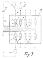
- FIG. 3 shows an embodiment of the switching device according to the invention, in which a predetermined number of switches 2 are arranged in the form of a matrix on a type of switch panel 18, each switch being a reed relay 2, as in FIG Fig. 1 shown.
- these reed relays 2 are preferably modified with respect to one another in such a way that each individual reed relay 2 can be actuated individually, for which purpose corresponding actuating magnets 3 must be provided, as is not shown in FIG. 3 for the sake of simplicity.
- Such a switch matrix or switch panel 18 can, for example, also be attached directly behind a glass pane of a motor vehicle, so that in In this case, a corresponding number of different elements or units within the motor vehicle can be switched on and off individually with the aid of the respectively assigned actuating magnet, preferably a coded mutual assignment between each individual reed relay 2 on the matrix 18 and each individual actuating magnet 3 is provided.
- Such a magnetically actuated switchgear is secured against unauthorized interference by third parties.
- the switching device according to the invention except z. B. in motor vehicle door lock deicing systems can also be installed in general for vehicle and front door locks.
Landscapes
- Lock And Its Accessories (AREA)
- Window Of Vehicle (AREA)
- Power-Operated Mechanisms For Wings (AREA)
- Switches That Are Operated By Magnetic Or Electric Fields (AREA)
Applications Claiming Priority (2)
| Application Number | Priority Date | Filing Date | Title |
|---|---|---|---|
| DE3917441 | 1989-05-30 | ||
| DE3917441A DE3917441A1 (de) | 1989-05-30 | 1989-05-30 | Schaltvorrichtung |
Publications (2)
| Publication Number | Publication Date |
|---|---|
| EP0400453A2 true EP0400453A2 (fr) | 1990-12-05 |
| EP0400453A3 EP0400453A3 (fr) | 1992-05-27 |
Family
ID=6381598
Family Applications (1)
| Application Number | Title | Priority Date | Filing Date |
|---|---|---|---|
| EP19900109657 Withdrawn EP0400453A3 (fr) | 1989-05-30 | 1990-05-21 | Dispositif de commutation |
Country Status (3)
| Country | Link |
|---|---|
| EP (1) | EP0400453A3 (fr) |
| JP (1) | JPH03214532A (fr) |
| DE (1) | DE3917441A1 (fr) |
Cited By (2)
| Publication number | Priority date | Publication date | Assignee | Title |
|---|---|---|---|---|
| US5551267A (en) * | 1994-04-15 | 1996-09-03 | Briggs & Stratton Corporation | Anti-magnetic tampering system for automobile ignition lock |
| US7016744B2 (en) | 1999-12-10 | 2006-03-21 | Scientific Generics Limited | Man-machine interface |
Families Citing this family (2)
| Publication number | Priority date | Publication date | Assignee | Title |
|---|---|---|---|---|
| US6958551B2 (en) | 2002-06-25 | 2005-10-25 | Strattec Security Corporation | Vehicle coded ignition lock using a magnetic sensor |
| DE102005036218A1 (de) * | 2005-08-02 | 2007-02-08 | Bayerische Motoren Werke Ag | Kraftfahrzeug mit einer Schaltvorrichtung |
Family Cites Families (17)
| Publication number | Priority date | Publication date | Assignee | Title |
|---|---|---|---|---|
| DE1918594U (de) * | 1965-04-03 | 1965-06-24 | Rokal G M B H | Elektrisch heizbares schloss. |
| DE1948380U (de) * | 1966-08-31 | 1966-10-27 | Heinz Baldamus | Elektroschalter fuer indirekte betaetigung. |
| DE6922264U (de) * | 1969-06-03 | 1974-12-12 | Alfred Schneidereit | Dauer-magnet-schliessvorrichtung fuer schloesser aller art |
| JPS5638938B2 (fr) * | 1973-08-06 | 1981-09-09 | ||
| DE2543754A1 (de) * | 1975-10-01 | 1977-04-14 | Industronic Ind Elect Gmbh | Gegen betaetigung durch unbefugte gesicherter schalter |
| DE2613416A1 (de) * | 1976-03-29 | 1977-10-06 | Siegfried Ing Grad Weisser | Elektronisches schloss fuer die schaerfung und entschaerfung von alarmanlagen |
| DE7627955U1 (de) * | 1976-09-07 | 1977-02-24 | Schoepfer, Otto, 7000 Stuttgart | Tuerschloss |
| CH621847A5 (en) * | 1977-06-06 | 1981-02-27 | Saseb Ag | Locking arrangement on a vehicle |
| AT366849B (de) * | 1977-07-27 | 1982-05-10 | Evva Werke | Beidseitige magnetisierung und kodierung von schluesselmagnetpillen und/oder rotormagnetpillen fuer magnetschloesser |
| JPS58120974A (ja) * | 1982-01-14 | 1983-07-19 | 日産自動車株式会社 | 開閉体のロツク装置 |
| GB2128027B (en) * | 1982-10-01 | 1985-11-06 | Electronic Components Ltd | Gearbox indicator switch |
| DE3441105A1 (de) * | 1984-11-10 | 1986-05-22 | Bayerische Motoren Werke AG, 8000 München | Vorrichtung zur diebstahl- sicherung eines kraftfahrzeug-teiles |
| DE3514149A1 (de) * | 1985-04-19 | 1986-10-23 | Sachs Systemtechnik Gmbh, 8720 Schweinfurt | Magnetschluesselanordnung |
| JPS61282566A (ja) * | 1985-06-06 | 1986-12-12 | マイクロニック株式会社 | キ−センサ |
| DE8524526U1 (de) * | 1985-08-24 | 1987-01-02 | Kunz, Manfred, 1000 Berlin | Sicherheitsbeschlag für ein Türschloß |
| DE3538841A1 (de) * | 1985-10-31 | 1987-05-21 | Permag Gmbh | Magnetfeldbetaetigte sicherheits-kontakteinrichtung |
| JPS63152830A (ja) * | 1986-12-17 | 1988-06-25 | 渡部 公正 | マグネツトスイツチ |
-
1989
- 1989-05-30 DE DE3917441A patent/DE3917441A1/de not_active Ceased
-
1990
- 1990-05-21 EP EP19900109657 patent/EP0400453A3/fr not_active Withdrawn
- 1990-05-29 JP JP2137320A patent/JPH03214532A/ja active Pending
Cited By (2)
| Publication number | Priority date | Publication date | Assignee | Title |
|---|---|---|---|---|
| US5551267A (en) * | 1994-04-15 | 1996-09-03 | Briggs & Stratton Corporation | Anti-magnetic tampering system for automobile ignition lock |
| US7016744B2 (en) | 1999-12-10 | 2006-03-21 | Scientific Generics Limited | Man-machine interface |
Also Published As
| Publication number | Publication date |
|---|---|
| EP0400453A3 (fr) | 1992-05-27 |
| JPH03214532A (ja) | 1991-09-19 |
| DE3917441A1 (de) | 1990-12-13 |
Similar Documents
| Publication | Publication Date | Title |
|---|---|---|
| EP0809743B2 (fr) | Cle electronique | |
| DE2704478C2 (de) | Diebstahlsicherungssystem für Kraftfahrzeuge | |
| DE19617038A1 (de) | Schließsystem, insbesondere für Kraftfahrzeuge | |
| EP1808336A1 (fr) | Dispositif de contrôle d'accès pour des véhicules à moteur | |
| DE2911630A1 (de) | Zentralgesteuerte verschlusseinrichtung fuer kraftfahrzeugtueren | |
| DE3008964C2 (de) | Schaltungsanordnung für eine zentralgesteuerte Verschlußeinrichtung mit Diebstahlsicherung für Kraftfahrzeugtüren | |
| EP0689964A1 (fr) | Commande à distance à installer dans un véhicule | |
| DE2750052A1 (de) | Tasten-kombinationsschloss | |
| EP0313772B1 (fr) | Dispositif combiné de verrouillage central et d'anti-vol pour serrures d'automobiles | |
| EP1581710A1 (fr) | Dispositif pour verrouiller et deverrouiller une porte de vehicule | |
| DE69103580T2 (de) | Zentralverriegelung für die Türen eines Autos. | |
| EP0315766B1 (fr) | Dispositif pour verrouiller des portes d'entrée en activant un avertisseur d'effraction | |
| EP0400453A2 (fr) | Dispositif de commutation | |
| DE2735999C2 (de) | Zentralverriegelungseinrichtung, insbesondere für die Türen von Kraftfahrzeugen | |
| DE3530834A1 (de) | Zentralverriegelungseinrichtung | |
| DE4315758C1 (de) | Sicherungssystem | |
| DE19500682C1 (de) | Verriegelungsvorrichtung für Kraftfahrzeuge | |
| DE19746608C1 (de) | Diebstahlschutzsystem für ein Kraftfahrzeug | |
| DE10225368C1 (de) | Schließzylinder mit kontaktloser Übertragung eines Signals | |
| DE69414807T2 (de) | Diebstahlschutzvorrichtung sowie Verfahren zu deren Steuerung für Kraftfahrzeuge mit fernsteuerbarer Verriegelung | |
| EP0405061A1 (fr) | Dispositif pour fixer des clefs de secours | |
| DE4341333B4 (de) | Verfahren zum Betreiben einer elektronischen Wegfahrsperre und elektronische Wegfahrsperre für Kraftfahrzeuge | |
| DE3703590C1 (en) | Circuit arrangement for activating a central locking system | |
| DE8534021U1 (de) | Schließvorrichtung mit elektronischem Identifizierungssystem | |
| EP0921046B1 (fr) | Dispositif anti-vol pour véhicules à moteur |
Legal Events
| Date | Code | Title | Description |
|---|---|---|---|
| PUAI | Public reference made under article 153(3) epc to a published international application that has entered the european phase |
Free format text: ORIGINAL CODE: 0009012 |
|
| AK | Designated contracting states |
Kind code of ref document: A2 Designated state(s): AT BE CH DE DK ES FR GB GR IT LI LU NL SE |
|
| PUAL | Search report despatched |
Free format text: ORIGINAL CODE: 0009013 |
|
| AK | Designated contracting states |
Kind code of ref document: A3 Designated state(s): AT BE CH DE DK ES FR GB GR IT LI LU NL SE |
|
| STAA | Information on the status of an ep patent application or granted ep patent |
Free format text: STATUS: THE APPLICATION IS DEEMED TO BE WITHDRAWN |
|
| 18D | Application deemed to be withdrawn |
Effective date: 19921128 |