EP0400534B1 - Dispositif pour l'ouverture pivotante et basculante d'une fenêtre ou porte-fenêtre - Google Patents
Dispositif pour l'ouverture pivotante et basculante d'une fenêtre ou porte-fenêtre Download PDFInfo
- Publication number
- EP0400534B1 EP0400534B1 EP90110072A EP90110072A EP0400534B1 EP 0400534 B1 EP0400534 B1 EP 0400534B1 EP 90110072 A EP90110072 A EP 90110072A EP 90110072 A EP90110072 A EP 90110072A EP 0400534 B1 EP0400534 B1 EP 0400534B1
- Authority
- EP
- European Patent Office
- Prior art keywords
- window
- pin
- cable
- tilt
- box
- Prior art date
- Legal status (The legal status is an assumption and is not a legal conclusion. Google has not performed a legal analysis and makes no representation as to the accuracy of the status listed.)
- Expired - Lifetime
Links
Images


Classifications
-
- E—FIXED CONSTRUCTIONS
- E05—LOCKS; KEYS; WINDOW OR DOOR FITTINGS; SAFES
- E05D—HINGES OR SUSPENSION DEVICES FOR DOORS, WINDOWS OR WINGS
- E05D15/00—Suspension arrangements for wings
- E05D15/48—Suspension arrangements for wings allowing alternative movements
- E05D15/52—Suspension arrangements for wings allowing alternative movements for opening about a vertical as well as a horizontal axis
- E05D15/5214—Corner supports
-
- E—FIXED CONSTRUCTIONS
- E05—LOCKS; KEYS; WINDOW OR DOOR FITTINGS; SAFES
- E05C—BOLTS OR FASTENING DEVICES FOR WINGS, SPECIALLY FOR DOORS OR WINDOWS
- E05C9/00—Arrangements of simultaneously actuated bolts or other securing devices at well-separated positions on the same wing
-
- E—FIXED CONSTRUCTIONS
- E05—LOCKS; KEYS; WINDOW OR DOOR FITTINGS; SAFES
- E05D—HINGES OR SUSPENSION DEVICES FOR DOORS, WINDOWS OR WINGS
- E05D15/00—Suspension arrangements for wings
- E05D15/48—Suspension arrangements for wings allowing alternative movements
- E05D15/52—Suspension arrangements for wings allowing alternative movements for opening about a vertical as well as a horizontal axis
- E05D15/526—Safety devices
-
- E—FIXED CONSTRUCTIONS
- E05—LOCKS; KEYS; WINDOW OR DOOR FITTINGS; SAFES
- E05B—LOCKS; ACCESSORIES THEREFOR; HANDCUFFS
- E05B53/00—Operation or control of locks by mechanical transmissions, e.g. from a distance
- E05B53/003—Operation or control of locks by mechanical transmissions, e.g. from a distance flexible
-
- E—FIXED CONSTRUCTIONS
- E05—LOCKS; KEYS; WINDOW OR DOOR FITTINGS; SAFES
- E05Y—INDEXING SCHEME ASSOCIATED WITH SUBCLASSES E05D AND E05F, RELATING TO CONSTRUCTION ELEMENTS, ELECTRIC CONTROL, POWER SUPPLY, POWER SIGNAL OR TRANSMISSION, USER INTERFACES, MOUNTING OR COUPLING, DETAILS, ACCESSORIES, AUXILIARY OPERATIONS NOT OTHERWISE PROVIDED FOR, APPLICATION THEREOF
- E05Y2900/00—Application of doors, windows, wings or fittings thereof
- E05Y2900/10—Application of doors, windows, wings or fittings thereof for buildings or parts thereof
- E05Y2900/13—Type of wing
- E05Y2900/146—Shutters
-
- E—FIXED CONSTRUCTIONS
- E05—LOCKS; KEYS; WINDOW OR DOOR FITTINGS; SAFES
- E05Y—INDEXING SCHEME ASSOCIATED WITH SUBCLASSES E05D AND E05F, RELATING TO CONSTRUCTION ELEMENTS, ELECTRIC CONTROL, POWER SUPPLY, POWER SIGNAL OR TRANSMISSION, USER INTERFACES, MOUNTING OR COUPLING, DETAILS, ACCESSORIES, AUXILIARY OPERATIONS NOT OTHERWISE PROVIDED FOR, APPLICATION THEREOF
- E05Y2900/00—Application of doors, windows, wings or fittings thereof
- E05Y2900/10—Application of doors, windows, wings or fittings thereof for buildings or parts thereof
- E05Y2900/13—Type of wing
- E05Y2900/148—Windows
-
- Y—GENERAL TAGGING OF NEW TECHNOLOGICAL DEVELOPMENTS; GENERAL TAGGING OF CROSS-SECTIONAL TECHNOLOGIES SPANNING OVER SEVERAL SECTIONS OF THE IPC; TECHNICAL SUBJECTS COVERED BY FORMER USPC CROSS-REFERENCE ART COLLECTIONS [XRACs] AND DIGESTS
- Y10—TECHNICAL SUBJECTS COVERED BY FORMER USPC
- Y10T—TECHNICAL SUBJECTS COVERED BY FORMER US CLASSIFICATION
- Y10T292/00—Closure fasteners
- Y10T292/08—Bolts
- Y10T292/0801—Multiple
- Y10T292/0834—Sliding
- Y10T292/0836—Operating means
- Y10T292/0841—Flexible
Definitions
- the present invention relates to a device for the shutter-like and tilt-down opening of a window.
- a device which comprises a rod which is mounted on an upright and is usually termed "cremone bolt"; said rod, actuated by a handle, acts by means of adapted devices on the arm of the upper supporting hinge and on a tilt-down abutment which is applied to the lower corner of the window and is adapted to allow shutter-like and tilt-down rotations.
- This known kind of device is structurally very complicated, since it is composed of a plurality of parts which can be mutually assembled; said device must furthermore be adapted according to the specific dimensions of the windows, so that some of its components must be shaped to size during assembly.
- composition of this known system is further complicated by the fact that if it is to be applied on irregular or "vaulted” windows it is necessary to further adapt its components to the specific shape of said window.
- Said devices are made of galvanized steel: the zinc plating wears at the points of contact between the fixed points and the movable points, allowing the forming of rust which compromises operation in the course of time.
- DE-A-3402780 shows a device which prevents a window from escaping out of its frame when it is in a tilt-down opening condition.
- This device comprises a lower hinge formed by a cylindrical male element which is accommodated in a bushing inserted in a seat. The terminal end of this male element has a smaller diameter section which terminates in an enlarged portion.
- the seat presents, at the bottom, a cylindrical cavity provided with a protrusion. When the window is in its tilt-down opening position, this enlarged portion engages with said protrusion, preventing said male element from escaping out of its seat.
- CH-A-421 746 shows a device as defined in the preamble of the appended claim 1.
- the aim of the subject of the present application is therefore to eliminate the disadvantages described above in known kinds by providing a device which, when applied to a window, allows to achieve the optimum shutter-like and tilt-down opening thereof.
- Another important object is to provide a device which is structurally simple so as to allow rapid assembly thereof onto windows.
- Another important object is to provide a device which can be applied to windows of different sizes in a rapid and easy manner, without forcing the installer to keep in stock a considerable number of parts according to the specific installation to be performed.
- Another important object is to provide a device which has a structurally simple safety against incorrect shutter-like opening maneuver starting from the tilt-down opening condition.
- Not least object is to provide a device which associates the preceding characteristics with that of having modest costs and of being reliable and safe in use and in the course of time.
- the reference numeral 1 indicates a window or door-window comprised of an upper cross-member 2 and a lower cross-member 3 connected by a pair of uprights indicated by the numerals 4 and 5.
- an upper hinge 52 at least temporarily connects the upper portion of the upright 4 of the window to a fixed frame 34.
- This upper hinge 52 is adapted, as will be described hereafter, to allow the window to open in a shutter-like fashion, in which the upright 4 remains vertical and the window rotates about an axis which is parallel to the extension of the upright 4, or to allow the window to open in a tilt-down manner, in which the window 1 rotates about an axis which is parallel to the extension of the lower cross member 3.
- a lower hinge 68 which connects the lower portion of the upright 4 to the fixed frame 34 is adapted, as will be described hereafter, to allow the window to achieve both the shutter-like and tilt-down opening as described above.
- Connection means 37,45 and 51 between the lower, middle and upper portions respectively of the upright 5 and the fixed frame 34 are also provided which are adapted to allow for the shutter-like or tilt-down opening of the window, and such connection means will be described in detail hereafter.
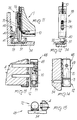
- the device for selecting and activating the shutter-like and tilt-down opening of the window 1 comprises a box 6 composed of a first and a second half-shell, indicated by the reference numerals 7 and 8, which are mutually associable.
- Said box is arranged at the upright 5, and a handle 9 is associated therewith and can be actuated by the user.
- Means are provided within said box 6 for the tensioning of at least one traction element which, in the illustrated embodiment, is constituted by a first cable 10 and by a second cable 11 preferably made of steel.
- Such cables 10 and 11 are associated with the upper hinge 52, the lower hinge 68, and the connection means 37 and 51 in such a manner so as to allow the shutter-like or tilt-down opening of the window, depending upon the degree of tensioning of said cables.
- Said means for tensioning the cables are constituted by a cam 12 which has an actuation means seat in which the handle 9 is inserted; upon rotation of the handle 9, the cam 12 interacts simultaneously with a first dowel 13 and with a second dowel 14 which have an essentially cylindrical shape.
- the cam 12 has a thickness approximately equal to the interspace between said first and said second half-shell and has, at said half-shells, profiles with a substantially mutually inverted configuration.
- the cam 12 advantageously has a first side profile which interacts at the first half-shell 7 with the first dowel 13 and a second side profile which interacts at the second half-shell 8 with the second dowel 14.
- the first side cam profile and the second side cam profile of the cam 12 are substantially mutually inverted, and this configuration, as will be shown hereafter, allows for the shutter-like opening or the tilt-down opening of the window, depending upon the degree of rotation of the cam 12 itself.
- the cam 12 has, at its first side profile, a first planar region 15 on which the first dowel 13 rests when the window is closed; one end of said dowel 13 is accommodated at an adapted seat provided in the first half-shell 7, whereas the other one interacts with a first wing 16 of a first slider 17 which has an essentially L-shaped configuration.
- An adapted first pawl 18 is provided at the first wing 16 and protrudes from the opposite side with respect to the one which interacts with the first dowel 13; a first cylindrical-helix compression spring 19 is arranged at said pawl.
- the first slider 17 slides at an adapted longitudinal seat provided on the first half shell 7, and securing means for the first cable 10, such as first Allen screws 21, are associated with the second wing 20 of the first slider 17 thereof.
- the cam 12 is furthermore provided, at its first side profile, with a second region 22 which is elliptical and is offset by 90 degrees clockwise with respect to the first region 15; said second region is followed, upon a rotation of another 90 degrees clockwise, by a third circular region 23 with constant radius.
- the cam 12 has, at its second side profile, a fourth planar region 24, which is also planar, at the second half-shell 8; said fourth planar region rests at the facing second dowel 14 when the window is closed.
- a fifth circular region 25 with constant radius is provided on the cam 12 at its second side profile after a 90-degree clockwise rotation with respect to said fourth region and is followed, after another clockwise 90-degree rotation, by a sixth elliptical region 26.
- one end of the second dowel 14 is accommodated, on the opposite side with respect to said first pin relative to the cam, in an adapted seat provided on said second half-shell; the other end interacts with a third wing 27 of a second slider 28 which has an L-shaped configuration and is slidably associated at an adapted seat provided on said second half-shell 8.
- a second pawl 29 protrudes at the third wing 27 in the opposite direction with respect to said second dowel 14 and interacts with an adapted second cylindrical-helix compression spring 30.
- Fixing means such as second Allen screws 32 for the second cable 11, which protrudes on the opposite side with respect to said first cable 10, are furthermore provided in the second slider 28 at the fourth wing 31.
- adapted access openings for said first and second Allen screws are naturally provided on said first and on said second half-shells.
- the cam 12 imparts a maximum upward movement to the first slider 17, which is connected to the first cable 10, and simultaneously imparts an intermediate downward movement to the second slider 28 which is connected to the second cable 11.
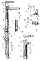
- the first cable 10 is in fact connected to a first pin 33 for the temporary closure of the window onto the fixed frame 34; said first pin is partially hollow for the passage of said first cable and has adapted coupling means for said cable, constituted by third Allen screws 35.
- the first pin 33 is therefore adjacent to the upright 5, and its end, which is partially removed toward the lower cross-member 3, is forced to protrude, when the window is closed, beyond said cross-member by means of an adapted third cylindrical-helix spring 36, within a first abutment 37 associated with said fixed frame 34.
- Said third spring 36 and said first pin 33 are slidably associated in an adapted seat provided longitudinally on a first box-like body 38 which can be rigidly associated with the upright 5 and is upwardly perforated for the passage of the first cable 10.
- a maximum movement imparted to the first slider 17 corresponds to a 90-degree counterclockwise rotation of the handle 9 and allows the disengagement of the end of said first pin 33 from said abutment 37.
- Said abutment is internally provided with a first inclined surface 39 adapted to facilitate the tilt-down opening of the window.
- the cam 12 interacts with the first dowel 13 at the third region 23 which places said first dowel in an intermediate position which is in any case sufficient to allow the partial protrusion of the free end of the first pin 33 from the first box-like body 38.
- Said box-like body furthermore comprises a means adapted to prevent the window from being lifted in the tilt-down condition, said means being constituted by a lug 40 which protrudes on the opposite side with respect to said upright 5 and is accommodated inside an adapted cavity 41 provided on a plate 42 rigidly associated with said fixed frame 34.
- the cam 12 interacts with the second dowel 14 at the fifth region 25 with constant radius, thus forcing the second slider 28 to perform an intermediate movement with respect to the maximum movement which can be achieved with a further 90-degree rotation.
- a movement of the second slider 28 toward the lower cross-member 3 therefore entails the tensioning of the cable 11, to which the end of a second intermediate closure pin 43 is pivoted.
- Said closure pin has an essentially L-shaped configuration, and its other free end protrudes transversely to the upright 5 toward the facing fixed frame 34 within an adapted second abutment 44.
- the second pin 43 is accommodated within a second box-like body 45 which is perforated above and below for the passage of the second cable 11, and said second pin 43 is slidably associable therein; its position with respect to the second cable 11 can be determined by means of adapted fourth Allen screws 46 and forced in its positioning by means of an adapted fourth cylindrical-helix compression spring 47 adapted to force said second pin toward the upper cross-member 2.
- a further pin with a configuration similar to that of the first pin 33 and of the first box like body 38 with which it is associated, except for the presence of a lug which performs the function of the lug indicated by the numeral 40, must be applied at the corner between the upper cross-member and the upright 5.
- Said further pin in order to perform the upper closure, is naturally connected to the first cable 10 and can be accommodated, upon a counterclockwise 90-degree rotation from the condition in which the window is closed to the condition in which it is open shutter-like, entirely within its own box-like body.
- This condition is in any case also achieved upon a further 90-degree rotation of the handle to pass from the condition in which the door is open shutter like to the condition in which it is open in a tilt-down manner.
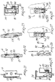
- the device is furthermore constituted by means for coupling to an upper hinge 52 which is adapted to couple the fixed frame 34 at the corner formed by the upper cross-member 2 and by the upright 4.
- Said hinge 52 is coupled, by means of a C-shaped plate, to the end of a first rod 54 which constitutes a compass-like arm 57 together with a second rod 55 which is associated with said first rod by means of an adapted fulcrum 56.
- the rod 54 is rigidly associated with the plate 53, i.e., preferably by welding.
- the third pin 64 does not interact with the plate 53 since it is caused to enter the seat by compressing the spring 66.
- the rod 54 constitutes the only interconnection element acting between the fixed frame which is coupled to the upper hinge 52 and the window.
- the plate 53 is connected to the upper hinge 52 and rotates together therewith.
- the above-mentioned compass arm is movable in a per se known manner and thus will be no further described herein.
- Said compass-like arm has, in the interspace between the fulcrum 56 and the plate 53, an articulation 58 which is rotatably associated, at one end, at an adapted support 59 which protrudes from a third box-like body 60 rigidly associated at the upper crosspiece 2.
- Said articulation 58 supports the entire window when it is open shutter-like.
- a slider 61 is instead provided at the free end of the second rod 55 and is slidable within an adapted longitudinal groove 62 provided on said third box-like body 60, which has adapted holes for the passage of the second cable 11.
- a pair of undulated springs 63 is advantageously provided inside the longitudinal groove 62; said springs are adapted to allow a certain movement of the slider 61 within said longitudinal groove 62.
- the third box-like body 60 is provided, proximate to the end adjacent to the plate 53, with a seat for a third pin 64 which is shaped like the first pin 33 and is therefore provided with fifth Allen screws 65 which can be accessed from the outside to secure the second cable 11 which is transmitted at the upright 2, said third pin 64 being partially hollowed out.
- a fifth cylindrical-helix spring 66 is furthermore provided and is adapted to force said third pin toward a facing hole 67 provided on a wing of said plate 53.
- the function of the third pin 64 is as follows: when the window is closed, it connects the upright 2 to the plate 53 and protrudes into the hole 67 toward the hinge 52.
- the cam 12 imparts a movement to the second dowel 14 which imparts a first slight downward movement to the second slider 28, and this causes the partial backward motion of the third slider 64, but said third slider maintains its engagement with the hole 67 provided on the wing of the plate 63: it is thus still possible to perform a shutter-like opening.
- the third pin 64 no longer affects the hole 67 of the wing of the plate 53, allowing to tilt down the window by virtue of the presence of the compass-like arm 57.
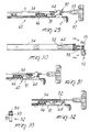
- Figures 29, 30, 31, 32 and 33 illustrate a further embodiment of the coupling to the upper hinge 52, and therefore to the first rod 54, of the third box-like body 60 which is rigidly associated at the upper crosspiece 2.
- the third box-like body 60 has, proximate to the end adjacent to the plate 53, which is hollow and rigidly associated with the upper hinge 52, a seat for a hook 91 which is connected to the second cable 11 and is slidable axially to said seat in contrast with an adapted fifth spring 66.
- Said hook 91 interacts with a third pivot 64 which is shaped similarly to the second pivot 43 and can therefore be accommodated within the seat for said hook 91 or be pushed out of it toward the overlying first rod 54 to position itself within an adapted slot 92 defined longitudinally to said first rod 54.
- the configuration of the mutually interacting ends of the hook 91 and of the third pivot 64 is such that a first rotation of the handle through ninety degrees obtains an axial sliding of the hook 91 without imparting any movement to said third pivot 64.
- the hook 91 Upon a subsequent rotation through ninety degrees imparted to the handle, the hook 91 imparts a movement to the third pivot 64, as seen from figure 32, forcing it to disengage from the slot 92 and arrange itself within the seat defined on the third box-like body 60.
- Tilt down opening is thus allowed.
- a sixth screw 93 which is rotatably associated at the plate 53 and controls the axial movement of a square element 94 which is slidably associable at said plate 53.
- the device finally comprises a lower hinge 68 which is axially aligned with the upper hinge 52.
- Said lower hinge 68 is advantageously inverted, in that it comprises a male element 69, constituted by a pin 70 of adjustable height, which is provided, at its outer end, with a ball 71 which can be accommodated in a countershaped seat provided on the female element 72 which is coupled to the fixed frame 34.
- Said lower hinge 68 is therefore a spherical hinge 30 advantageously made of synthetic material, provided with sliding action for shutter-like opening and articulated action for tilt-down opening: the use of the ball 71 thus allows to prevent the window from assuming, when open, a certain preset position on one hand and, on the other, to achieve the optimum inclination of the pin 70 in the tilt-down opening condition, even in case of incorrect maneuvers such as for example simultaneous shutter-like and tilt-down opening.
- the pin 70 follows the inclination of the window without leading to breakage or damage of the hardware.
- Said lower hinge 68 can advantageously be adjustable both vertically and laterally and be reversible.
- FIGS 27 and 28 illustrate a further embodiment of the lower hinge 168, which is again constituted by a pin 170 the outer end whereof has a first cylindrical portion 188 followed by a second portion 189 in the shape of a spherical dome.
- the seat for said first and second portions defined on the female element 172 is essentially cylindrical, with a seventh region 190 in the shape of a truncated cone with its vertex directed opposite to the pin 170 proximate to the upper opening for the insertion of said first and second portions.
- an anular tang 200 adapted to prevent the pin 170 from escaping out of this region.
- this configuration allows to locate the first and second portions of the pin 170 within the seat defined on the female element 172, preventing mutual extraction if the window is placed in the tilt-down condition.
- the first portion 188 arranges itself at the seventh frustum-shaped region 190, against said anular tang 200, and thus interacts in abutment with said female element 172 if extraction thereof is attempted.
- the device is furthermore constituted by means adapted to prevent the rotation of the handle 9 from the tilt-down opening condition to the shutter-like one, said means being constituted, as shown in figures 6,7 and 8, by an adapted pendulum 73 which is articulated at one end within an adapted seat provided above the cam 12 at the second half-shell 8 and is arranged adjacent, at the other end, to said second half-shell 8 when the window is arranged vertically and therefore in the shutter-like closure and opening conditions.
- the free end of the pendulum 73 can therefore be positioned at an adapted recess 74 provided transversely to the cam 12.
- the device can furthermore have, for example at the upper cross member 2 and at the lower cross-member 3, further pins having the same configuration as the second pin 43 which is not movable perpendicular to the respective cross-member so as to affect a fourth abutment 75 and a fifth abutment 76 associated with the facing fixed frame 34.
- the means suitable for preventing the rotation of the handle from the tilt-down opening condition to the shutter-like one can again be constituted by a suitable pendulum 173 which has an essentially triangular configuration and is arranged outside the box 6 at the front surface 79 from which the first Allen screws 21 and the second Allen screws 32 slightly advantageously protrude.
- the pendulum 173 is pivoted, at its vertex, perpendicular to the front surface 79 in a region adjacent to the second Allen screws 32, and a T-shaped seat 80, with its stem directed toward said vertex, is defined at the other end of the pendulum 173.
- the pendulum 173 arranges itself as shown in figure 22, and the seat 80 allows the axial sliding, with respect to the seat itself, of the first Allen screws 21 which protrude beyond the front surface 79 which is arranged on a plane which is parallel to that of said pendulum 73.
- Figures 24, 25 and 26 illustrate a further embodiment for the means suitable for preventing the rotation of the handle from the tilt-down opening condition to the shutter-like one: said means are constituted by a wedge-like element 81 associable at the fixed frame 34 and by a hook 82 eccentrically pivoted at a wing of a support 83 which has an essentially U-shaped configuration and is associated with the upright 4 or with both uprights.
- Said support 83 is arranged longitudinally to said uprights.
- the first cable 10 can slide within the support 83; a cylinder 84 is advantageously rigidly coupled to said cable and can slide along said support 83.
- the hook 82 is pivoted to a wing of the support 83 and is forced, by means of an adapted sixth spring 85, so as to arrange itself adjacent at the first cable 10 and therefore on the opposite side with respect to the wedge-like element 81.
- the first cable 10 arranges itself at an adapted cavity 86 defined on the hook 82.
- said hook has a wall 87 which is slightly curved proximate to the axis of pivoting to the support 83 so that said hook 82 disengages from the cylinder 84 by interacting with the wedge-like element 81 when the window is closed.
- said cylinder 84 is arranged below said hook 82 so that when the window opens in a tilt-down manner the first cable 10 is prevented from sliding axially due to the interaction of the cylinder 84 with said hook 82, which is forced by the sixth spring 85 adjacent to said first cable 10.
- the invention has achieved the proposed aim and objects, a device having been provided which allows to achieve the optimum shutter-like and tilt-down opening of a window while having a very simple structure and being rapidly mountable on said windows.
- the device is furthermore manufactured with corrosion-resistant, oxidation-resistant and wear-resistant materials such as brass and thermoplastic materials, whereas the cables are preferably made of galvanized or stainless steel so to be used for example even in a particularly oxidizing or corrosive atmosphere such as for example proximate to the sea.
- the box used can furthermore be applied both for rightward and leftward openings, making the amount of stockable material very small, since the use of the cables and pin is independent of the specific configuration of the window.
- the device is furthermore provided with a safety against the incorrect shutter-like opening movement starting from the tilt-down opening condition.
- figures 19 and 20 illustrate a different embodiment for the means adapted to prevent the window from being lifted or opened in the tilt-down condition; said means again comprises a plate 142 with which a cylindrical bush 177 is rotatably associated, said bush having a diametrical groove 178 toward the first box-like body 138 which acts as the temporary seat for the lug 140 which protrudes therefrom.
- the lug imparts a rotation to the bush which therefore locks said window against possible lifting or opening of the lower cross-member.
- the materials and dimensions of the individual components of the device can be the most pertinent according to the specific requirements.
Landscapes
- Engineering & Computer Science (AREA)
- Mechanical Engineering (AREA)
- Wing Frames And Configurations (AREA)
- Operating, Guiding And Securing Of Roll- Type Closing Members (AREA)
- Closing And Opening Devices For Wings, And Checks For Wings (AREA)
- Window Of Vehicle (AREA)
Claims (34)
- Dispositif pour l'ouverture par rapport à un châssis fixe (34) d'une fenêtre ou d'une porte-fenêtre (1) autour d'un axe vertical et d'un axe horizontal, la fenêtre comprenant une traverse supérieure (2) et une traverse inférieure (3) reliées par une paire de montants (4,5), le dispositif comportant une poignée (9) associée de façon rotative à l'un desdits montants, et un boîtier (6), agencé sur un desdits montants, qui est muni de moyens (12), actionnés par ladite poignée (9), pour mettre sous tension au moins un élément de traction (10,11) qui actionne une pluralité de broches (33,43,64) pour la fermeture temporaire sur ledit châssis fixe (34) et pour le couplage à une charnière supérieure (52) pour l'ouverture autour de soit un axe vertical, soit un axe horizontal, ledit dispositif comprenant une charnière inférieure (168) ayant une broche (170) qui est reliée à ladite fenêtre et qui présente une extrémité externe faisant saillie de la fenêtre, la charnière inférieure comportant de plus un élément femelle faisant face vers le haut (172) rigidement associée audit châssis fixe et ayant un siège dans lequel ladite extrémité externe de la broche (170) est logée,
caractérisé en ce que ladite extrémité externe de la broche (170) comporte une première portion cylindrique (188) suivie par une seconde portion (189) sous forme d'un dôme sphérique, le siège de l'élément femelle (172) est essentiellement cylindrique et présente une zone supérieure (190) sous forme d'un cône tronqué agencé de façon adjacente à la première portion cylindrique (188) de l'extrémité externe de la broche (170), ladite zone supérieure (190) présentant un talon annulaire (200) disposé à l'extrémité supérieure de ladite zone supérieure (190) adapté pour empêcher l'échappement de ladite broche (170) hors de ladite zone supérieure (190) quand ladite fenêtre est dans une condition d'ouverture basculée vers le bas. - Dispositif selon la revendication 1,
caractérisé en que ledit boîtier (6) est constitué d'un corps unique ou d'une première moitié de coque (7) et d'une seconde moitié de coque (8) mutuellement associables, agencé sur un desdits montants et avec lequel ladite poignée (9) est associée, ladite poignée (9) pouvant être actionnée par l'utilisateur, des moyens étant prévus à l'intérieur dudit boîtier (6) pour la mise sous tension dudit élément de traction, tel que des premier (10) et second (11) câbles de traction réalisés de préférence en acier. - Dispositif selon les revendications 1 et 2,
caractérisé en ce que lesdits moyens de tension dont constitués par une came (12) qui présente un siège pour l'actionnement au moyen de ladite poignée (9), ladite came (12) interagissant avec des première (13) et seconde (14) goupilles, lesquelles présentent une forme sensiblement cylindrique, ladite came (12) ayant une largeur qui est approximativement égale à l'espacement entre ladite première moitié de coque (7) et ladite seconde moitié de coque (8) et présentant des profils ayant une configuration différente sur lesdites moitiés de coque. - Dispositif selon les revendications 1 et 3,
caractérisé en ce que ladite came (12) présente, sur ladite première moitié de coque (7), une première zone planaire (15) sur laquelle ladite première goupille (13) repose quand la fenêtre (1) est fermée, une extrémité de ladite première goupille (13) étant logée sur un siège adapté prévu sur ladite moitié de coque (7), tandis que l'autre extrémité interagit avec une première branche (16) d'un premier coulisseau (17) qui présente une configuration sensiblement en forme de L, ledit premier coulisseau étant associé de façon coulissante à un siège longitudinal adapté prévu sur ladite première moitié de coque (7). - Dispositif selon les revendications 1 et 4,
caractérisé en ce qu'un premier cliquet adapté (18) est prévu sur ladite première branche (16) dudit premier coulisseau (17) et fait saillie sur le côté opposé par rapport au côté qui interagit avec ladite première goupille (13), un premier ressort de compression hélicoïdal (19) étant situé sur ledit cliquet (18), des moyens de verrouillage pour ledit premier câble, tels que des premières vis Allen (21), étant associés à la seconde branche (20) dudit premier coulisseau. - Dispositif selon les revendications 1 et 5,
caractérisé en ce que ladite came (12) est munie de plus d'une seconde zone (22) ayant une configuration elliptique qui est décalée de 90° dans le sens des aiguilles d'une montre par rapport à ladite première zone (15) et est suivie, après une autre rotation de 90° dans le sens des aiguilles d'une montre, par une troisième zone (23) de rayon constant. - Dispositif selon les revendications 1 et 6,
caractérisé en ce que ladite came (12) présente une quatrième zone (24) sur ladite seconde moitié de coque (8), ladite quatrième zone (24) étant également planaire et reposant, quand la fenêtre (1) est fermée, sur ladite seconde goupille (14) en vis-à-vis, une cinquième zone (25) de rayon constant étant prévue sur ladite came (12) après rotation de 90° dans le sens des aiguilles d'une montre par rapport à ladite quatrième zone (24), ladite cinquième zone (25) étant suivie, après une autre rotation de 90° dans le sens des aiguilles d'une montre, par une sixième zone (26) de configuration elliptique. - Dispositif selon les revendications 1 et 7,
caractérisé en ce qu'une extrémité de ladite seconde goupille (14) est logée, au niveau de ladite seconde moitié de coque (8), sur le côté opposé par rapport à ladite première goupille (13) relativement à ladite came (12), dans un siège adapté prévu sur ladite seconde moitié de coque (8), son autre extrémité interagissant avec une troisième branche (27) d'un second coulisseau (28) qui présente une configuration en forme de L et est associé de façon coulissante à un siège longitudinal adapté, à nouveau prévu sur ladite seconde moitié de coque (8). - Dispositif selon les revendications 1 et 8,
caractérisé en ce qu'un second cliquet (29) fait saillie sur ladite troisième branche (27) dudit second coulisseau (28) dans la direction opposée par rapport à ladite seconde goupille (14), ledit second cliquet (29) interagissant avec un second ressort de compression hélicoïdal adapté (30), ledit second coulisseau (28) ayant une quatrième branche (31) munie de moyens de couplage, tels que des secondes vis Allen (32), pour ledit second câble (11) qui fait saillie sur le côté opposé par rapport audit premier câble (10). - Dispositif selon les revendications 1 et 9,
caractérisé en ce que des ouvertures d'accès pour lesdites premières (21) et secondes (32) vis Allen sont prévues à la fois sur lesdites première (7) et seconde (8) moitiés de coque. - Dispositif selon les revendications 1 et 9,
caractérisé en ce que, lors d'une rotation de 90°, qui est dans le sens inverse des aiguilles d'une montre, si ladite poignée (9) est utilisée sur le montant gauche (5), imprimée à ladite poignée (9), ladite came (12) imprime un mouvement vers le haut maximal audit premier coulisseau (17) relié audit premier câble (10) et imprime simultanément un mouvement vers le bas intermédiaire audit second coulisseau (28) qui est relié audit second câble (11) de façon à permettre l'ouverture, analogue à celle d'un volet, de ladite fenêtre (1). - Dispositif selon les revendications 1 et 11,
caractérisé en ce que ledit premier câble (10) est relié à une première broche (33) pour la fermeture temporaire de ladite fenêtre (1) sur un châssis fixe (34), ladite première broche (33) étant partiellement creuse pour le passage dudit premier câble (10) et ayant des moyens adaptés, constitués par des troisièmes vis Allen (35), pour verrouiller ledit câble (10), ladite première broche (33) étant ainsi agencée de façon adjacente à l'un desdits montants ou aux deux montants, son extrémité qui est partiellement retirée vers ladite traverse inférieure (3) étant forcée à saillir, quand la fenêtre est fermée, au-delà de ladite traverse inférieure (3) au moyen d'un troisième ressort hélicoïdal adapté (36) à l'intérieur d'une première butée (37) qui est associée audit châssis fixe (34). - Dispositif selon les revendications 1 et 12,
caractérisé en ce que ledit troisième ressort (36) et la première broche (33) sont associés de façon coulissante à un siège longitudinal adapté prévu sur un premier corps en forme de boîtier (38) qui peut être associé rigidement avec un desdits montants qui est perforé vers le haut pour le passage dudit premier câble (10). - Dispositif selon les revendications 1 et 13,
caractérisé en ce qu'un mouvement maximal imprimé audit premier coulisseau (17) pour permettre le désengagement de l'extrémité libre de ladite première broche (33) de ladite première butée (37) correspond à une rotation de 90° dans le sens inverse des aiguilles d'une montre de ladite poignée (9), ladite butée (37) étant munie intérieurement d'une première surface inclinée (39) adaptée pour faciliter l'ouverture par basculement vers le bas de ladite fenêtre (1), ladite came (12) interagissant, dans cette dernière condition, qui correspond à une rotation de 180° de ladite poignée (9) en partant de la condition de fermeture, avec ladite première goupille (13) au niveau de ladite troisième zone (23) de façon à agencer ladite première goupille (13) dans une position intermédiaire qui est, dans tous les cas, suffisante pour permettre la saillie partielle de l'extrémité libre de ladite première broche (33) à partir dudit premier corps en forme de boîtier (38). - Dispositif selon les revendications 1 et 14,
caractérisé en ce que ledit premier corps en forme de boîtier (38) comprend de plus des moyens adaptés pour éviter à ladite fenêtre d'être soulevée si elle est dans la condition basculée vers le bas, lesdits moyens étant constitués par une patte (40) qui fait saillie du côté opposé par rapport à un desdits montants et est logée à l'intérieur d'une cavité adaptée (41) prévue sur une plaque (42) qui est rigidement couplée audit châssis fixe (34). - Dispositif selon les revendications 1 et 15,
caractérisé en ce que l'extrémité d'une seconde broche de fermeture intermédiaire (43) pivote par rapport audit second câble (11), ladite seconde broche (43) présentant une configuration sensiblement en forme de L, l'autre extrémité de celle-ci, qui est libre, faisant saillie transversalement vers un (5) desdits montants vers ledit châssis fixe (34) en vis-à-vis à l'intérieur d'une seconde butée adaptée (44), ladite seconde broche (43) étant logée de façon coulissante à l'intérieur d'un second corps en forme de boîtier (45) qui est perforé au-dessus et au-dessous pour le passage dudit seconde câble (11) et présente des quatrièmes vis Allen (46) pour -la fixation dudit second câble (11), ladite seconde broche (43) étant forcée vers ladite traverse supérieure (2) au moyen d'un quatrième ressort de compression hélicoïdal adapté (47). - Dispositif selon les revendications 1 et 16,
caractérisé en ce que l'extrémité libre de ladite seconde broche (43) réalise un mouvement qui est approximativement perpendiculaire par rapport audit second corps en forme de boîtier (45), qui est muni, vers le haut, d'une seconde surface inclinée (48) qui interagit avec l'extrémité supérieure de ladite seconde broche (43) pendant le positionnement de la poignée (9) à partir de la condition dans laquelle la fenêtre (1) est ouverte de façon analogue à un volet vers la condition dans laquelle la fenêtre (1) est fermée grâce à la présence dudit quatrième ressort (47). - Dispositif selon les revendications 1 et 17,
caractérisé en ce que le mouvement de translation transversale de l'extrémité libre de ladite seconde broche (43) pendant l'étape de rotation de 90° dans le sens inverse des aiguilles d'une montre de la poignée (9) partir de la condition dans laquelle la fenêtre (1) est fermée vers la condition dans laquelle la fenêtre (1) est ouverte de façon analogue à un volet, est permis par la présence d'une troisième surface inclinée adaptée (49) qui est prévue sur ladite seconde broche (43) et interagit avec une patte sous-jacente et en vis-à-vis (50) dudit second corps en forme de boîtier (45). - Dispositif selon les revendications 1 et 18,
caractérisé en ce qu'il comprend des moyens pour le couplage à une charnière supérieure (52) qui est adaptée pour coupler ledit châssis fixe (34) au coin formé par la traverse supérieure (2) et par un (4) desdits montants, ladite charnière (52) étant couplée, au moyen d'une plaque en forme de C (53), à l'extrémité d'une première tige (54) qui constitue, en même temps qu'une seconde tige (55) qui est associée à ladite première tige (54) au moyen d'un pivot adapté (56), un bras de compas (57) qui présente, dans l'espacement entre ledit pivot (56) et ladite plaque (53), une articulation (58) qui est associée de façon rotative, à une extrémité, à un support adapté (59) qui fait saillie d'un troisième corps en forme de boîtier (60) qui est rigidement associé à la traverse supérieure (2). - Dispositif selon les revendications 1 et 19,
caractérisé en ce qu'un coulisseau (61) est prévu à l'extrémité libre de ladite seconde tige (55), ledit coulisseau (61) pouvant coulisser à l'intérieur d'une gorge longitudinale adaptée (62) qui est prévue sur ledit troisième corps en forme de boîtier (60), ledit troisième corps en forme de boîtier (60) ayant des trous adaptés pour le passage dudit second câble (11). - Dispositif selon les revendications 1 et 20,
caractérisé en ce qu'une paire de ressorts ondulés (63) est prévue à l'intérieur de ladite gorge longitudinale (62), lesdits ressorts (63) étant adaptés pour permettre un certain mouvement dudit coulisseau (61) à l'intérieur de ladite gorge longitudinale (62). - Dispositif selon les revendications 1 et 21,
caractérisé en ce que ledit troisième corps en forme de boîtier (60) est muni, à proximité de l'extrémité qui est adjacente à ladite plaque (53), d'un siège pour une troisième broche (64) qui présente des cinquièmes vis Allen qui peuvent être accessibles de l'extérieur pour verrouiller ledit second câble (11), ladite troisième broche (64) étant partiellement creusée pour la transmission dudit second câble (11) sur le montant (4) et étant forcée par un cinquième ressort (66) vers un trou (67) en vis-à-vis prévu sur une branche de ladite plaque (53), ladite troisième broche (64) reliant, quand la fenêtre (1) est fermée, ledit montant supérieur (4) à ladite plaque (53), ladite broche (64) faisant saillie à l'intérieur dudit trou (67) vers ladite charnière (52). - Dispositif selon les revendications 1 et 22,
caractérisé en ce que ladite troisième broche (64) maintient un engagement avec ledit trou (67) prévu sur ladite branche de ladite plaque (53) suivant une rotation de 90° dans le sens inverse des aiguilles d'une montre de ladite poignée (9) pour passer vers la condition dans laquelle la fenêtre (1) est ouverte de façon analogue à un volet. - Dispositif selon les revendications 1 et 23,
caractérisé en ce que ladite troisième broche (64) est désengagée dudit trou (67) prévu sur ladite branche de ladite plaque (53) après une rotation de 180° à partir de la condition de fermeture vers la condition d'ouverture basculée vers le bas. - Dispositif selon les revendications 1 et 24,
caractérisé en ce que l'articulation inférieure (168) est axialement alignée avec ladite articulation supérieure (52) et peut être ajustée à la fois verticalement et latéralement, ladite articulation (168) étant avantageusement inversée en permettant ainsi d'abaisser le point de rotation sans avoir des contraintes sur ladite première broche de fermeture (33). - Dispositif selon une ou plusieurs des revendications précédentes,
caractérisé en ce qu'il comprend des moyens (73) adaptés pour empêcher la rotation de ladite poignée (9) à partir de la condition d'ouverture basculée vers le bas vers la condition d'ouverture analogue à celle d'un volet, lesdits moyens étant constitués par un balancier adapté (73) qui est articulé, à son extrémité supérieure, dans un siège adapté prévu au-dessus de ladite came (12) sur ladite seconde moitié de coque (8) et agencé à son autre extrémité, de façon adjacente à la paroi arrière de ladite seconde moitié de coque (8) quand la fenêtre (1) est agencée verticalement et, en conséquence, dans les conditions d'ouverture et de fermeture analogues à celles d'un volet. - Dispositif selon les revendications 1 et 26,
caractérisé en ce que l'extrémité libre dudit balancier (73) peut être agencée dans un évidement adapté (74) prévu transversalement à ladite came (12) si ladite fenêtre (1) est agencée dans la condition d'ouverture basculée vers le bas, toute autre rotation dans une direction quelconque étant empêchée pour ladite came (12) dans ladite position à moins que la fenêtre (1) soit tout d'abord ramenée vers une position verticale. - Dispositif selon une ou plusieurs des revendications précédentes,
caractérisé en ce qu'il comprend des moyens adaptés pour empêcher le soulèvement ou l'ouverture de ladite fenêtre (1) dans la condition d'ouverture basculée vers le bas, constitués par une bague cylindrique (177) qui est associée de façon rotative à une plaque (142) qui est fixée audit châssis fixe (34), ladite bague (177) ayant une gorge diamétrale (178) qui est le siège temporaire pour une patte (140) qui fait saillie à partir dudit premier corps en forme de boîtier (138). - Dispositif selon une ou plusieurs des revendications précédentes,
caractérisé en ce que lesdits moyens appropriés pour empêcher la rotation de ladite poignée (9) à partir de la condition d'ouverture basculée vers le bas vers celle analogue à un volet sont constitués par un balancier (173) de configuration triangulaire qui est agencé extérieurement et parallèlement audit boîtier (6) sur la surface frontale (79) à partir de laquelle lesdites premières (21) et secondes (32) vis Allen font saillie, ledit balancier (173) étant pivoté librement au sommet dans une zone adjacente auxdites secondes vis Allen (32) et ayant, sur le côté opposé, un siège en forme de T (80), d'où la tige, qui est dirigée vers ledit sommet, permet le coulissement axial desdites premières vis Allen (21) quand la fenêtre (1) est ouverte comme un volet, les branches dudit siège (80) verrouillant le coulissement desdites premières vis Allen (21) quand la fenêtre (1) est ouverte d'une façon basculée vers le bas. - Dispositif selon une ou plusieurs des revendications précédentes,
caractérisé en ce que lesdits moyens adaptés pour empêcher la rotation de ladite poignée (9) à partir de la condition d'ouverture basculée vers le bas vers celle analogue à un volet sont constitués par un élément en forme de coin (81) qui peut être associé audit châssis fixe (34) et en fait saillie, et par un crochet (82) qui est pivoté de façon excentrique sur une branche d'un support (83) qui présente une forme de U et peut être associé avec un desdits montants ou les deux, ledit élément en forme de coin (81) interagissant avec ledit crochet (82) quand la fenêtre (1) est fermée. - Dispositif selon les revendications 1 et 30,
caractérisé en ce qu'au moins ledit premier câble (10) coulisse axialement audit support (83), au moins un cylindre (84) étant rigidement associé audit câble (10), ledit cylindre (84) venant en butée, quand la fenêtre (1) est dans la position ouverte basculée vers le bas, avec ledit crochet sus-jacent (82), ledit crochet (82) étant forcé de s'agencer lui-même, au moyen d'un sixième ressort adapté (85), de façon adjacente audit premier câble (10) au niveau d'une cavité adaptée (86) définie sur ledit crochet (82). - Dispositif selon les revendications 1 et 31,
caractérisé en ce que la paroi (87) dudit crochet (82) qui interagit avec ledit élément en forme de coin (81) est légèrement incurvée à proximité de l'axe de pivotement par rapport audit support (83) de façon à permettre, quand la fenêtre (1) est fermée, le désengagement dudit crochet (82) dudit câble (10) et du cylindre (84), ledit cylindre (84) pouvant coulisser librement par rapport audit support (83) lors d'une activation dudit premier câble (10). - Dispositif selon une ou plusieurs des revendications précédentes,
caractérisé en ce que ledit troisième corps en forme de boîtier (60) présente, à proximité de l'extrémité adjacente à ladite plaque (53), qui est creuse et rigidement associée à ladite charnière supérieure (52), un siège pour un crochet (91) qui est relié audit second câble (11) et peut coulisser axialement audit siège à l'encontre dudit cinquième ressort (66), ledit crochet (91) interagissant de façon sélective avec un troisième pivot (64) qui est conformé de façon semblable audit second pivot (43) et peut être totalement logé à l'intérieur dudit siège pour ledit crochet (91) quand la fenêtre (1) est dans la condition ouverte basculée vers le bas ou faire saillie au niveau d'une fente adaptée définie longitudinalement sur ladite première tige sus-jacente (54) quand la fenêtre (1) est fermée ou ouverte de façon analogue à un volet. - Dispositif selon les revendications 1 et 33,
caractérisé en ce que, de façon à permettre l'ajustement de la position latérale dudit volet, ladite articulation supérieure (52) présente, au niveau de ladite plaque (53), une sixième vis (93) qui est associée de façon librement rotative avec celle-ci et est adaptée pour mettre en oeuvre le mouvement axial d'un élément carré (94) qui peut être associé de façon coulissante à ladite plaque (53) et est couplé à ladite première tige (54).
Applications Claiming Priority (2)
| Application Number | Priority Date | Filing Date | Title |
|---|---|---|---|
| IT8982552A IT1235293B (it) | 1989-06-01 | 1989-06-01 | Dispositivo per l'apertura ad anta e a ribalta di una finestra o di una porta finestra. |
| IT8255289 | 1989-06-01 |
Publications (2)
| Publication Number | Publication Date |
|---|---|
| EP0400534A1 EP0400534A1 (fr) | 1990-12-05 |
| EP0400534B1 true EP0400534B1 (fr) | 1996-07-24 |
Family
ID=11318739
Family Applications (1)
| Application Number | Title | Priority Date | Filing Date |
|---|---|---|---|
| EP90110072A Expired - Lifetime EP0400534B1 (fr) | 1989-06-01 | 1990-05-28 | Dispositif pour l'ouverture pivotante et basculante d'une fenêtre ou porte-fenêtre |
Country Status (7)
| Country | Link |
|---|---|
| US (1) | US5076015A (fr) |
| EP (1) | EP0400534B1 (fr) |
| AT (1) | ATE140757T1 (fr) |
| DE (1) | DE69027893T2 (fr) |
| ES (1) | ES2091210T3 (fr) |
| IT (1) | IT1235293B (fr) |
| RU (1) | RU1822457C (fr) |
Families Citing this family (65)
| Publication number | Priority date | Publication date | Assignee | Title |
|---|---|---|---|---|
| US5533798A (en) * | 1993-10-15 | 1996-07-09 | Steelcase Inc. | Lock system for casegoods |
| US5398447A (en) * | 1994-02-28 | 1995-03-21 | Morse; Allen D. | Centrally located tilt-in window handle |
| US6679002B2 (en) | 1994-07-28 | 2004-01-20 | 420820 Ontario Limited | Retractable screen system |
| GB9605462D0 (en) * | 1996-03-15 | 1996-05-15 | Murray Brian | Lock |
| GB2325700A (en) * | 1996-03-15 | 1998-12-02 | Latch Developments Limited | Lock |
| FR2752010B1 (fr) * | 1996-07-31 | 1998-10-16 | Ferco Int Usine Ferrures | Ferrure d'articulation notamment un support d'angle, pour porte, fenetre ou analogue |
| FR2756863B1 (fr) * | 1996-12-06 | 1999-01-22 | Ferco Int Usine Ferrures | Dispositif de securite de type antifausse manoeuvre pour une ferrure de verrouillage d'un vantail |
| WO1999007600A1 (fr) * | 1997-08-05 | 1999-02-18 | Her Majesty The Queen As Represented By The Minister Of National Defence Of Her Majesty's Canadian Government | Systeme pour issue de secours |
| US5881498A (en) * | 1997-09-27 | 1999-03-16 | Thermo-Roll Window Corp. | Tilt and turn window lock system |
| DE19817108A1 (de) * | 1998-04-17 | 1999-10-21 | Molitor Elektrotechnik Gmbh | Schließvorrichtung für Flügelfenster und Flügeltüren |
| US5992907A (en) * | 1998-04-27 | 1999-11-30 | Truth Hardware Corporation | Lock and tilt latch for sliding windows |
| DE20002467U1 (de) * | 2000-02-11 | 2000-05-04 | Gretsch-Unitas GmbH Baubeschläge, 71254 Ditzingen | Drehkippbeschlag |
| US6421960B1 (en) * | 2000-03-16 | 2002-07-23 | Francis Manzella | Safety-lock for multi-position tilt and turn window |
| US6817142B2 (en) | 2000-10-20 | 2004-11-16 | Amesbury Group, Inc. | Methods and apparatus for a single lever tilt lock latch window |
| US6568723B2 (en) | 2001-09-24 | 2003-05-27 | Ashland Paroducts, Inc. | Sash lock for a sash window |
| US7017957B2 (en) | 2001-09-24 | 2006-03-28 | Ashland Products, Inc. | Sash lock for a sash window |
| US6536163B1 (en) * | 2001-10-12 | 2003-03-25 | First Years Inc. | Operating child safety barriers |
| US7013603B2 (en) | 2001-11-07 | 2006-03-21 | Newell Operating Company | Integrated tilt/sash lock assembly |
| US8020904B2 (en) | 2001-11-07 | 2011-09-20 | Newell Operating Company | Integrated tilt/sash lock assembly |
| US6983963B2 (en) | 2002-01-29 | 2006-01-10 | Newell Operating Company | Forced entry resistance device for sash lock |
| US6607221B1 (en) | 2002-08-01 | 2003-08-19 | Gordon W. Elliott | Window latch system |
| GB2393476A (en) * | 2002-08-02 | 2004-03-31 | Maple & Son Ltd J | Door locking mechanism with secondary bolt |
| US7607262B2 (en) | 2002-11-07 | 2009-10-27 | Newell Operating Company | Integrated tilt/sash lock assembly |
| US6925758B2 (en) * | 2003-05-06 | 2005-08-09 | Newell Operating Company | Forced entry resistance device for sash window assembly |
| CA2534384C (fr) * | 2005-01-26 | 2011-12-13 | Truth Hardware Corporation | Mecanisme avec verrou et loquet a bascule integres pour fenetre coulissante |
| BE1016457A3 (nl) * | 2005-02-17 | 2006-11-07 | Parys Remi E Van | Vergrendelmechanisme voor een raam of dergelijke. |
| US7806287B2 (en) * | 2005-07-26 | 2010-10-05 | Bart Rouns | Bear-proof latch for a refuse container |
| US7976077B2 (en) | 2005-07-28 | 2011-07-12 | Newell Operating Company | Integrated tilt/sash lock assembly |
| US7510221B2 (en) | 2006-02-09 | 2009-03-31 | Newell Operating Company | Sash lock assembly having forced entry resistance |
| US11047157B1 (en) | 2006-03-28 | 2021-06-29 | Vision Industries Group, Inc. | Vent stop |
| US8235430B2 (en) | 2006-03-28 | 2012-08-07 | Vision Industries, Inc. | Window vent stop with flexible side engagement pieces |
| US10107021B1 (en) | 2006-03-28 | 2018-10-23 | Vision Industries Group, Inc. | Window vent stop with plastic spring member for bi-directional biasing of the tumbler |
| ITTO20060434A1 (it) * | 2006-06-15 | 2007-12-16 | Savio Spa | "gruppo di azionamento per serramenti" |
| USD554973S1 (en) | 2006-07-26 | 2007-11-13 | Newell Operating Company | Sash lock housing |
| USD553950S1 (en) | 2006-07-26 | 2007-10-30 | Newell Operating Company | Sash lock housing |
| USD554473S1 (en) | 2006-07-26 | 2007-11-06 | Newell Operating Company | Tilt-latch |
| USD553947S1 (en) | 2006-07-26 | 2007-10-30 | Newell Operating Company | Integrated tilt/sash lock assembly |
| USD554971S1 (en) | 2006-07-26 | 2007-11-13 | Newell Operating Company | Sash lock handle |
| US7963577B2 (en) * | 2007-09-25 | 2011-06-21 | Truth Hardware Corporation | Integrated lock and tilt-latch mechanism for a sliding window |
| USD575627S1 (en) | 2007-11-16 | 2008-08-26 | Newell Operating Company | Sash lock housing |
| BE1017949A5 (nl) * | 2008-01-17 | 2010-01-12 | Parys Remi E Van | Beslag van een raam en onderdelen daarvoor. |
| US8205920B2 (en) | 2008-04-28 | 2012-06-26 | Newell Operating Company | Sash lock with forced entry resistance |
| US8205919B2 (en) | 2008-04-28 | 2012-06-26 | Newell Operating Company | Sash lock with forced entry resistance |
| US8215685B2 (en) * | 2009-04-17 | 2012-07-10 | Newfrey, Llc | Double draw bar spring mechanism |
| US9840860B2 (en) | 2009-05-29 | 2017-12-12 | Vision Industries Group, Inc. | Double-action, adjustable, after-market sash stop |
| TW201237808A (en) * | 2011-02-11 | 2012-09-16 | Chandler Partners International Ltd | Autonomous door defense system and method |
| TWI451829B (zh) * | 2011-04-25 | 2014-09-01 | Compal Electronics Inc | 電子裝置及卡扣機構 |
| CN107476675B (zh) | 2011-08-23 | 2020-04-28 | 施拉奇锁有限责任公司 | 出口装置组件 |
| DE102012002960B4 (de) * | 2012-02-16 | 2014-08-21 | Assa Abloy Sicherheitstechnik Gmbh | Montagebaugruppe zur Montage einer Verriegelungseinrichtung |
| ES2524215B1 (es) * | 2013-06-04 | 2015-07-31 | Industrias E. Díaz, S.A. | Ventana extraíble, recambiable y sustituible de doble apertura |
| CN103556907A (zh) * | 2013-11-20 | 2014-02-05 | 王博 | 一种单扇双开柜门 |
| US10119310B2 (en) | 2014-03-06 | 2018-11-06 | Vision Industries Group, Inc. | Combination sash lock and tilt latch with improved interconnection for blind mating of the latch to the lock |
| US10865592B2 (en) | 2014-03-06 | 2020-12-15 | Vision Industries Group, Inc. | Sash lock and tilt latch also functioning as a window vent stop, with automatic locking upon closure |
| US10704297B2 (en) | 2014-03-06 | 2020-07-07 | Vision Industries, Inc. | Impact resistant lock and tilt latch combination for a sliding sash window |
| US10570652B2 (en) | 2014-03-06 | 2020-02-25 | Vision Industries Group, Inc. | Integrated sash lock and tilt latch combination using one lock for two tilt latches |
| US10844642B2 (en) | 2014-03-06 | 2020-11-24 | Vision Industries Group, Inc. | Combination four-position sash lock and tilt latch also functioning as a window opening control device |
| US11168492B1 (en) | 2017-02-16 | 2021-11-09 | Vision Industries Group, Inc. | Tamper resistant sash lock |
| US10633897B2 (en) | 2017-02-16 | 2020-04-28 | Vision Industries Group, Inc. | Tamper-resistant lock |
| US10844636B2 (en) | 2017-05-23 | 2020-11-24 | Vision Industries Group, Inc. | Combination forced entry resistant sash lock and tilt latch, also functioning as a window opening control device |
| US11118376B1 (en) | 2017-10-18 | 2021-09-14 | Vision Industries Group, Inc. | Combination sash lock and tilt latch and slidable window vent stop |
| US11168495B1 (en) | 2018-08-01 | 2021-11-09 | Vision Industries Group, Inc. | Automatically resetting window vent stop with dual safety features |
| US11187010B1 (en) | 2019-09-19 | 2021-11-30 | Vision Industries, Inc. | Forced-entry-resistant sash lock |
| US12428886B1 (en) | 2022-06-16 | 2025-09-30 | Vision Industries Group, Inc. | Forced entry resistant sash lock also configured to snap into the meeting rail of the sash window |
| US12359477B1 (en) | 2022-06-16 | 2025-07-15 | Vision Industries Group, Inc. | Window sash lock configured for screwless snap-in installation onto a meeting rail |
| US12467297B1 (en) | 2023-07-18 | 2025-11-11 | Vision Industries Group, Inc. | Window balance assembly with improved brake arrangement |
Citations (4)
| Publication number | Priority date | Publication date | Assignee | Title |
|---|---|---|---|---|
| DE2701583A1 (de) * | 1977-01-15 | 1978-07-20 | Bilstein August Fa | Beschlag fuer fenster, tueren o.dgl. |
| DE2836412A1 (de) * | 1978-08-19 | 1980-02-28 | Bilstein August Fa | Ecklager fuer kipp-schwenkfluegel von fenstern, tueren o.dgl. |
| DE3402780A1 (de) * | 1983-01-28 | 1984-08-02 | SLIM Società Lavorazioni Industriali Metalli S.p.A., Cisterna di Latina | Unteres kippschwenkscharnier von fenster, tuerfluegeln und aehnlichen |
| DE3503814A1 (de) * | 1985-02-05 | 1986-08-07 | SCHÜCO Heinz Schürmann GmbH & Co, 4800 Bielefeld | Drehkipp-ecklager fuer fenster oder tueren, insbesondere fuer kunststoffenster oder kunststofftueren |
Family Cites Families (39)
| Publication number | Priority date | Publication date | Assignee | Title |
|---|---|---|---|---|
| DE4749C (de) * | A. reitze in Hannover | Betriebsmechanismus für kleinere Maschinen | ||
| US913269A (en) * | 1908-06-30 | 1909-02-23 | Louis C Dalhousie | Door. |
| FR810435A (fr) * | 1936-08-31 | 1937-03-22 | Crémone perfectionnée pour la fermeture des fenêtres et des portes | |
| DE855509C (de) * | 1950-12-03 | 1952-11-13 | Ver Baubeschlag Gretsch Co | Hebefenster |
| DE1113162B (de) * | 1958-02-25 | 1961-08-24 | Ver Baubeschlag Gretsch Co | Bedienungsvorrichtung mit einem zugleich dreh- und kippbaren Bedienungshebel fuer Fenster- und Tuerfluegel od. dgl. |
| US2976070A (en) * | 1959-07-13 | 1961-03-21 | Fred W Gollbach | Latching mechanism |
| FR1261587A (fr) * | 1960-06-23 | 1961-05-19 | Crémone semi-automatique à entraînement par câble souple pour fenêtres ou autres applications | |
| US3027188A (en) * | 1961-01-26 | 1962-03-27 | Elmer C Eichstadt | Removable and reversible vehicle tailgate mounting |
| BE649653A (fr) * | 1963-06-26 | |||
| FR1397254A (fr) * | 1964-02-10 | 1965-04-30 | Commissariat Energie Atomique | Porte étanche |
| DE1559999A1 (de) * | 1964-02-11 | 1970-04-02 | Ver Baubeschlag Gretsch Co | Bedienungsvorrichtung fuer Schwenk-Kipp-Fluegel |
| CH404453A (fr) * | 1964-03-13 | 1965-12-15 | Marguelisch Arthur | Dispositif d'articulation d'un vantail sur son cadre |
| DE1525271A1 (de) * | 1965-01-07 | 1970-01-02 | Schunk & Ebe Gmbh | Sinterlager mit erhoehter Lebensdauer |
| CH436024A (de) * | 1965-04-23 | 1967-05-15 | Kuentz & Cie Ag | Fenster |
| DE1509684A1 (de) * | 1965-07-28 | 1969-11-06 | Mathes Kg Heinz | Aus einem Metall- oder Kunststoffprofil hergestelltes Fenster |
| US3406483A (en) * | 1967-03-16 | 1968-10-22 | Ford Motor Co | Combination hinge-latch device |
| BE758371A (fr) * | 1969-11-19 | 1971-05-03 | Boussois Souchon Neuvesel Sa | Fenetre a vantail du genre oscillo-battant |
| DE2059185B2 (de) * | 1970-12-02 | 1976-03-25 | Fa. Carl Fuhr, 5628 Heiligenhaus | Treibstangenverschluss fuer tueren, fenster oder dergleichen |
| DE2143979A1 (de) * | 1971-09-02 | 1973-03-08 | Bilstein August Fa | Betaetigungshebel mit rosette und darin eingebauter sperreinrichtung |
| FR2166636A5 (fr) * | 1971-12-31 | 1973-08-17 | Guerrini Jacques | |
| DE2206764A1 (de) * | 1972-02-12 | 1973-08-16 | Heinr Strenger Fa | Kipplager fuer schwenk- und kippbare fluegelrahmen von fenstern oder tueren |
| US3910611A (en) * | 1972-03-24 | 1975-10-07 | Cleveland Hardware & Forging | Multiple latch lock assembly and method |
| US3834747A (en) * | 1972-03-24 | 1974-09-10 | Cleveland Hardware & Forging | Multiple latch lock assembly and method |
| DE2231092A1 (de) * | 1972-06-24 | 1974-01-03 | Goldschmidt Geb | Betaetigungsvorrichtung fuer einen fensterbeschlag |
| DE2240345A1 (de) * | 1972-08-17 | 1974-02-28 | Frank Gmbh Wilh | Zugelement fuer fenster, tueren od.dgl. |
| US3911621A (en) * | 1973-10-23 | 1975-10-14 | Extrudart Metal Products Inc | Multi-purpose window |
| US4074462A (en) * | 1976-12-06 | 1978-02-21 | Extrudart Metal Products, Inc. | Multi-position window |
| DE2706013C2 (de) * | 1977-02-12 | 1984-05-30 | Siegenia-Frank Kg, 5900 Siegen | Treibstangenbeschlag an Fenstern, Türen od.dgl. aus Metall- oder Kunststoffprofilen |
| DE2734317C3 (de) * | 1977-07-29 | 1980-09-04 | Fa. Aug. Winkhaus, 4404 Telgte | Ecklager für Drehkippfenster |
| US4461160A (en) * | 1979-05-03 | 1984-07-24 | Brammall, Inc. | Self-latching, semi-automatic door lock and opener |
| US4339892A (en) * | 1980-10-09 | 1982-07-20 | Flour City Architectural Metals | Safety window of the tilt and turn type |
| EP0051309B2 (fr) * | 1980-11-03 | 2000-12-06 | Aug. Winkhaus GmbH & Co. KG | Fenêtre |
| US4392329A (en) * | 1980-12-11 | 1983-07-12 | Nippon Elumin Sash Co., Ltd. | Pivotable window moved between locked and opened positions by means of a single operating handle |
| DE3222678C2 (de) * | 1982-06-16 | 1986-05-22 | Josef Gartner & Co, 8883 Gundelfingen | Drehkippbeschlag |
| AT386040B (de) * | 1983-08-13 | 1988-06-27 | Rsb Holding & Management Ag | Einhand-drehkipp-beschlag fuer ein fenster |
| EP0150653B2 (fr) * | 1984-01-25 | 1994-07-06 | FERCO INTERNATIONAL Usine de Ferrures de BÀ¢timent Société à responsabilité limitée | Ferrure pour ouvrant à deux sens d'ouverture présentant des moyens de blocage de l'un des sens d'ouverture |
| GB2161201A (en) * | 1984-07-04 | 1986-01-08 | Hardware & Systems Patents Ltd | Fastening mechanism for doors or windows |
| GB2190704A (en) * | 1986-03-26 | 1987-11-25 | Smith Wallis & Company Limited | Window assemblies |
| DE3906794A1 (de) * | 1989-03-03 | 1990-09-06 | Bilstein August Gmbh Co Kg | Fenster mit einem drehbeweglichen, insbesondere drehkippbeweglichen fensterfluegel |
-
1989
- 1989-06-01 IT IT8982552A patent/IT1235293B/it active
-
1990
- 1990-05-28 EP EP90110072A patent/EP0400534B1/fr not_active Expired - Lifetime
- 1990-05-28 AT AT90110072T patent/ATE140757T1/de not_active IP Right Cessation
- 1990-05-28 DE DE69027893T patent/DE69027893T2/de not_active Expired - Fee Related
- 1990-05-28 ES ES90110072T patent/ES2091210T3/es not_active Expired - Lifetime
- 1990-05-29 US US07/529,428 patent/US5076015A/en not_active Expired - Fee Related
- 1990-05-31 RU SU904830233A patent/RU1822457C/ru active
Patent Citations (4)
| Publication number | Priority date | Publication date | Assignee | Title |
|---|---|---|---|---|
| DE2701583A1 (de) * | 1977-01-15 | 1978-07-20 | Bilstein August Fa | Beschlag fuer fenster, tueren o.dgl. |
| DE2836412A1 (de) * | 1978-08-19 | 1980-02-28 | Bilstein August Fa | Ecklager fuer kipp-schwenkfluegel von fenstern, tueren o.dgl. |
| DE3402780A1 (de) * | 1983-01-28 | 1984-08-02 | SLIM Società Lavorazioni Industriali Metalli S.p.A., Cisterna di Latina | Unteres kippschwenkscharnier von fenster, tuerfluegeln und aehnlichen |
| DE3503814A1 (de) * | 1985-02-05 | 1986-08-07 | SCHÜCO Heinz Schürmann GmbH & Co, 4800 Bielefeld | Drehkipp-ecklager fuer fenster oder tueren, insbesondere fuer kunststoffenster oder kunststofftueren |
Also Published As
| Publication number | Publication date |
|---|---|
| IT8982552A0 (it) | 1989-06-01 |
| DE69027893D1 (de) | 1996-08-29 |
| IT1235293B (it) | 1992-06-26 |
| ATE140757T1 (de) | 1996-08-15 |
| DE69027893T2 (de) | 1996-12-12 |
| ES2091210T3 (es) | 1996-11-01 |
| US5076015A (en) | 1991-12-31 |
| EP0400534A1 (fr) | 1990-12-05 |
| RU1822457C (ru) | 1993-06-15 |
Similar Documents
| Publication | Publication Date | Title |
|---|---|---|
| EP0400534B1 (fr) | Dispositif pour l'ouverture pivotante et basculante d'une fenêtre ou porte-fenêtre | |
| CA2210026C (fr) | Levier de commande pour loquet de fenetre anti-crochetage | |
| US5873199A (en) | Locking device for full tilt windows | |
| US6042156A (en) | Overcenter double jaw latch mechanism | |
| US6119398A (en) | Tilt window balance shoe assembly with three directional locking | |
| AU639631B2 (en) | A window operator and hinge structure | |
| KR102010377B1 (ko) | 회동식 창호시스템의 창호스테이바 유닛 | |
| CA1178309A (fr) | Mecanisme avec boulons a tete noyee | |
| US4880261A (en) | Remote latch mechanism | |
| AU679842B2 (en) | Draw latch with catch having kick-out action | |
| CA2050776A1 (fr) | Bras de retenue par friction | |
| CA2303055C (fr) | Charniere amelioree pour meubles et autres du meme genre, a bras mobile place a l'interieur du bras fixe | |
| US5148629A (en) | Right-handed and left-handed openable door device | |
| EP4006277B1 (fr) | Dispositif pour contraindre l'ouverture de portes ou de fenêtres | |
| US5620214A (en) | Sash latch | |
| CA2351190C (fr) | Ensemble de reglage de raccord a pivot | |
| EP1522667B1 (fr) | Dispositif d'ancrage à un volet d'une extrémité d'un élément flexible associé à un dispositif actionneur du volet | |
| IL42653A (en) | A hinge for cabinet doors and the like | |
| JPS5915336Y2 (ja) | ドア等の下部構造 | |
| AU6387194A (en) | A window stay | |
| JP3054382B2 (ja) | トリガ−機構付き扉用ロック装置 | |
| US20260036233A1 (en) | Fluid connector | |
| EP0450626B1 (fr) | Charnière en deux parties pour un battant, de préférence de meuble | |
| KR950007544Y1 (ko) | 도어 잠금장치 | |
| EP0894925A1 (fr) | Serrure pour porte de véhicule automobile |
Legal Events
| Date | Code | Title | Description |
|---|---|---|---|
| PUAI | Public reference made under article 153(3) epc to a published international application that has entered the european phase |
Free format text: ORIGINAL CODE: 0009012 |
|
| AK | Designated contracting states |
Kind code of ref document: A1 Designated state(s): AT BE CH DE DK ES FR GB GR IT LI NL SE |
|
| 17P | Request for examination filed |
Effective date: 19910507 |
|
| 17Q | First examination report despatched |
Effective date: 19930504 |
|
| GRAH | Despatch of communication of intention to grant a patent |
Free format text: ORIGINAL CODE: EPIDOS IGRA |
|
| GRAH | Despatch of communication of intention to grant a patent |
Free format text: ORIGINAL CODE: EPIDOS IGRA |
|
| GRAA | (expected) grant |
Free format text: ORIGINAL CODE: 0009210 |
|
| AK | Designated contracting states |
Kind code of ref document: B1 Designated state(s): AT BE CH DE DK ES FR GB GR IT LI NL SE |
|
| PG25 | Lapsed in a contracting state [announced via postgrant information from national office to epo] |
Ref country code: GR Free format text: LAPSE BECAUSE OF FAILURE TO SUBMIT A TRANSLATION OF THE DESCRIPTION OR TO PAY THE FEE WITHIN THE PRESCRIBED TIME-LIMIT Effective date: 19960724 Ref country code: DK Effective date: 19960724 |
|
| REF | Corresponds to: |
Ref document number: 140757 Country of ref document: AT Date of ref document: 19960815 Kind code of ref document: T |
|
| REG | Reference to a national code |
Ref country code: CH Ref legal event code: NV Representative=s name: ROTTMANN, ZIMMERMANN + PARTNER AG |
|
| ET | Fr: translation filed | ||
| REF | Corresponds to: |
Ref document number: 69027893 Country of ref document: DE Date of ref document: 19960829 |
|
| ITF | It: translation for a ep patent filed | ||
| PG25 | Lapsed in a contracting state [announced via postgrant information from national office to epo] |
Ref country code: SE Effective date: 19961024 |
|
| REG | Reference to a national code |
Ref country code: ES Ref legal event code: FG2A Ref document number: 2091210 Country of ref document: ES Kind code of ref document: T3 |
|
| PGFP | Annual fee paid to national office [announced via postgrant information from national office to epo] |
Ref country code: CH Payment date: 19970501 Year of fee payment: 8 |
|
| PGFP | Annual fee paid to national office [announced via postgrant information from national office to epo] |
Ref country code: ES Payment date: 19970505 Year of fee payment: 8 |
|
| PGFP | Annual fee paid to national office [announced via postgrant information from national office to epo] |
Ref country code: GB Payment date: 19970516 Year of fee payment: 8 |
|
| PLBE | No opposition filed within time limit |
Free format text: ORIGINAL CODE: 0009261 |
|
| STAA | Information on the status of an ep patent application or granted ep patent |
Free format text: STATUS: NO OPPOSITION FILED WITHIN TIME LIMIT |
|
| PGFP | Annual fee paid to national office [announced via postgrant information from national office to epo] |
Ref country code: NL Payment date: 19970531 Year of fee payment: 8 |
|
| PGFP | Annual fee paid to national office [announced via postgrant information from national office to epo] |
Ref country code: BE Payment date: 19970604 Year of fee payment: 8 |
|
| 26N | No opposition filed | ||
| PGFP | Annual fee paid to national office [announced via postgrant information from national office to epo] |
Ref country code: AT Payment date: 19980526 Year of fee payment: 9 |
|
| PGFP | Annual fee paid to national office [announced via postgrant information from national office to epo] |
Ref country code: DE Payment date: 19980527 Year of fee payment: 9 |
|
| PG25 | Lapsed in a contracting state [announced via postgrant information from national office to epo] |
Ref country code: GB Free format text: LAPSE BECAUSE OF NON-PAYMENT OF DUE FEES Effective date: 19980528 |
|
| PGFP | Annual fee paid to national office [announced via postgrant information from national office to epo] |
Ref country code: FR Payment date: 19980528 Year of fee payment: 9 |
|
| PG25 | Lapsed in a contracting state [announced via postgrant information from national office to epo] |
Ref country code: ES Free format text: LAPSE BECAUSE OF EXPIRATION OF PROTECTION Effective date: 19980529 |
|
| PG25 | Lapsed in a contracting state [announced via postgrant information from national office to epo] |
Ref country code: LI Free format text: LAPSE BECAUSE OF NON-PAYMENT OF DUE FEES Effective date: 19980531 Ref country code: CH Free format text: LAPSE BECAUSE OF NON-PAYMENT OF DUE FEES Effective date: 19980531 Ref country code: BE Free format text: LAPSE BECAUSE OF NON-PAYMENT OF DUE FEES Effective date: 19980531 |
|
| BERE | Be: lapsed |
Owner name: OTLAV S.P.A. Effective date: 19980531 |
|
| PG25 | Lapsed in a contracting state [announced via postgrant information from national office to epo] |
Ref country code: NL Free format text: LAPSE BECAUSE OF NON-PAYMENT OF DUE FEES Effective date: 19981201 |
|
| REG | Reference to a national code |
Ref country code: CH Ref legal event code: PL |
|
| GBPC | Gb: european patent ceased through non-payment of renewal fee |
Effective date: 19980528 |
|
| NLV4 | Nl: lapsed or anulled due to non-payment of the annual fee |
Effective date: 19981201 |
|
| PG25 | Lapsed in a contracting state [announced via postgrant information from national office to epo] |
Ref country code: AT Free format text: LAPSE BECAUSE OF NON-PAYMENT OF DUE FEES Effective date: 19990528 |
|
| PG25 | Lapsed in a contracting state [announced via postgrant information from national office to epo] |
Ref country code: FR Free format text: LAPSE BECAUSE OF NON-PAYMENT OF DUE FEES Effective date: 20000131 |
|
| PG25 | Lapsed in a contracting state [announced via postgrant information from national office to epo] |
Ref country code: DE Free format text: LAPSE BECAUSE OF NON-PAYMENT OF DUE FEES Effective date: 20000301 |
|
| REG | Reference to a national code |
Ref country code: FR Ref legal event code: ST |
|
| REG | Reference to a national code |
Ref country code: ES Ref legal event code: FD2A Effective date: 20000201 |
|
| PG25 | Lapsed in a contracting state [announced via postgrant information from national office to epo] |
Ref country code: IT Free format text: LAPSE BECAUSE OF NON-PAYMENT OF DUE FEES Effective date: 20050528 |