EP0400576A1 - Coude - Google Patents
Coude Download PDFInfo
- Publication number
- EP0400576A1 EP0400576A1 EP90110159A EP90110159A EP0400576A1 EP 0400576 A1 EP0400576 A1 EP 0400576A1 EP 90110159 A EP90110159 A EP 90110159A EP 90110159 A EP90110159 A EP 90110159A EP 0400576 A1 EP0400576 A1 EP 0400576A1
- Authority
- EP
- European Patent Office
- Prior art keywords
- edge
- bent pipe
- metal plate
- curved
- fold
- Prior art date
- Legal status (The legal status is an assumption and is not a legal conclusion. Google has not performed a legal analysis and makes no representation as to the accuracy of the status listed.)
- Granted
Links
Images


Classifications
-
- B—PERFORMING OPERATIONS; TRANSPORTING
- B21—MECHANICAL METAL-WORKING WITHOUT ESSENTIALLY REMOVING MATERIAL; PUNCHING METAL
- B21D—WORKING OR PROCESSING OF SHEET METAL OR METAL TUBES, RODS OR PROFILES WITHOUT ESSENTIALLY REMOVING MATERIAL; PUNCHING METAL
- B21D13/00—Corrugating sheet metal, rods or profiles; Bending sheet metal, rods or profiles into wave form
-
- B—PERFORMING OPERATIONS; TRANSPORTING
- B21—MECHANICAL METAL-WORKING WITHOUT ESSENTIALLY REMOVING MATERIAL; PUNCHING METAL
- B21C—MANUFACTURE OF METAL SHEETS, WIRE, RODS, TUBES, PROFILES OR LIKE SEMI-MANUFACTURED PRODUCTS OTHERWISE THAN BY ROLLING; AUXILIARY OPERATIONS USED IN CONNECTION WITH METAL-WORKING WITHOUT ESSENTIALLY REMOVING MATERIAL
- B21C37/00—Manufacture of metal sheets, rods, wire, tubes, profiles or like semi-manufactured products, not otherwise provided for; Manufacture of tubes of special shape
- B21C37/06—Manufacture of metal sheets, rods, wire, tubes, profiles or like semi-manufactured products, not otherwise provided for; Manufacture of tubes of special shape of tubes or metal hoses; Combined procedures for making tubes, e.g. for making multi-wall tubes
- B21C37/12—Making tubes or metal hoses with helically arranged seams
- B21C37/121—Making tubes or metal hoses with helically arranged seams with seams being neither welded nor soldered
-
- B—PERFORMING OPERATIONS; TRANSPORTING
- B21—MECHANICAL METAL-WORKING WITHOUT ESSENTIALLY REMOVING MATERIAL; PUNCHING METAL
- B21C—MANUFACTURE OF METAL SHEETS, WIRE, RODS, TUBES, PROFILES OR LIKE SEMI-MANUFACTURED PRODUCTS OTHERWISE THAN BY ROLLING; AUXILIARY OPERATIONS USED IN CONNECTION WITH METAL-WORKING WITHOUT ESSENTIALLY REMOVING MATERIAL
- B21C37/00—Manufacture of metal sheets, rods, wire, tubes, profiles or like semi-manufactured products, not otherwise provided for; Manufacture of tubes of special shape
- B21C37/06—Manufacture of metal sheets, rods, wire, tubes, profiles or like semi-manufactured products, not otherwise provided for; Manufacture of tubes of special shape of tubes or metal hoses; Combined procedures for making tubes, e.g. for making multi-wall tubes
- B21C37/12—Making tubes or metal hoses with helically arranged seams
- B21C37/124—Making tubes or metal hoses with helically arranged seams the tubes having a special shape, e.g. with corrugated wall, flexible tubes
- B21C37/125—Making tubes or metal hoses with helically arranged seams the tubes having a special shape, e.g. with corrugated wall, flexible tubes curved section, e.g. elbow
-
- B—PERFORMING OPERATIONS; TRANSPORTING
- B21—MECHANICAL METAL-WORKING WITHOUT ESSENTIALLY REMOVING MATERIAL; PUNCHING METAL
- B21C—MANUFACTURE OF METAL SHEETS, WIRE, RODS, TUBES, PROFILES OR LIKE SEMI-MANUFACTURED PRODUCTS OTHERWISE THAN BY ROLLING; AUXILIARY OPERATIONS USED IN CONNECTION WITH METAL-WORKING WITHOUT ESSENTIALLY REMOVING MATERIAL
- B21C37/00—Manufacture of metal sheets, rods, wire, tubes, profiles or like semi-manufactured products, not otherwise provided for; Manufacture of tubes of special shape
- B21C37/06—Manufacture of metal sheets, rods, wire, tubes, profiles or like semi-manufactured products, not otherwise provided for; Manufacture of tubes of special shape of tubes or metal hoses; Combined procedures for making tubes, e.g. for making multi-wall tubes
- B21C37/15—Making tubes of special shape; Making tube fittings
- B21C37/28—Making tube fittings for connecting pipes, e.g. U-pieces
- B21C37/286—Making tube fittings for connecting pipes, e.g. U-pieces starting from sheet material
-
- F—MECHANICAL ENGINEERING; LIGHTING; HEATING; WEAPONS; BLASTING
- F16—ENGINEERING ELEMENTS AND UNITS; GENERAL MEASURES FOR PRODUCING AND MAINTAINING EFFECTIVE FUNCTIONING OF MACHINES OR INSTALLATIONS; THERMAL INSULATION IN GENERAL
- F16L—PIPES; JOINTS OR FITTINGS FOR PIPES; SUPPORTS FOR PIPES, CABLES OR PROTECTIVE TUBING; MEANS FOR THERMAL INSULATION IN GENERAL
- F16L43/00—Bends; Siphons
- F16L43/001—Bends; Siphons made of metal
-
- Y—GENERAL TAGGING OF NEW TECHNOLOGICAL DEVELOPMENTS; GENERAL TAGGING OF CROSS-SECTIONAL TECHNOLOGIES SPANNING OVER SEVERAL SECTIONS OF THE IPC; TECHNICAL SUBJECTS COVERED BY FORMER USPC CROSS-REFERENCE ART COLLECTIONS [XRACs] AND DIGESTS
- Y10—TECHNICAL SUBJECTS COVERED BY FORMER USPC
- Y10T—TECHNICAL SUBJECTS COVERED BY FORMER US CLASSIFICATION
- Y10T29/00—Metal working
- Y10T29/49—Method of mechanical manufacture
- Y10T29/49428—Gas and water specific plumbing component making
- Y10T29/49444—Elbow or L-shaped fitting making
Definitions
- This invention relates to a bent pipe or elbow used at a corner portion of an airconditioning duct, an exhaust pipe, a drain pipe or the like to connect pipe sections.
- a bent pipe made by helically winding a metal strip and fastening together folded portions extending along its adjacent edges is known from Japanese Examined Patent Publications 59-27478 and 63-50595.
- Such a pipe is made from a metal strip having wide and narrow portions arranged alternately so that both side edges thereof will delineate moderately curved lines in a symmetrical relation.
- its edge portions were wasted. This will push up the cost.
- An object of the present invention is to provide a bent pipe which can be made without forming any scrap.
- the bent pipe according to the present invention is made by helically winding a strip of metal plate having one edge extending in a straight line and the other edge extending in a curved line to form wide portions and narrow portions alternately so that the narrow portions will be in juxtaposition with one another, and engaging together the one edge and the other edge of the metal plate.
- a double fold is formed along the straight edge and a single fold is formed along the curved edge and they are engaged and pressed together after the metal plate is wound helically.
- a metal plate is cut so that one of the longitudinal edges will extend in a straight line while the other in a curved line. This makes it possible to produce two metal strips out of a single metal plate without wasting any part of it and thus to reduce the cost remarkably.
- the provision of the straight edge will make it easier to manufacture forming rolls of an apparatus for producing bent pipes because they have many straight portions.
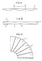
- Fig. 11 shows a strip of metal plate 2 for producing a bent pipe 1.
- This metal strip 2 has wide portions 2′ and narrow portions 2 ⁇ arranged alternately and has one of its longitudinal edges extending in a straight line and the other extending in a curved line.
- each portion between adjacent troughs X-X will form an annular piece as a part of the peripheral wall of the bent pipe 1 when the metal plate 2 is wound helically so that the narrow portions will be in juxtaposition with each other.
- the straight edge of each annular piece at portion between X - X has a length substantially equal to the diameter of the bent pipe 1 multiplied by ⁇ .
- two such metal strips 2 can be made by longitudinally cutting a single metal plate 3 in a curved line so as to form a pair of symmetrical portions. This will prevent the production of scrap.
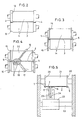
- the coiled metal plate 3 is drawn out into between a pair of first forming rolls 11 (Fig. 1) to form L-shaped bent portions 4 along both edges thereof by means of large-diameter annular plates 12 and small-diameter annular plates 13 provided at both ends of the respective forming rolls 11 (Fig. 2).
- the bent portions 4 thus made are then formed into U-shaped double folds 5 by cooperation of annular ribs 15 and annular grooves 16 provided at both ends of a pair of second forming rolls 14.
- the metal plate 3 is cut into two pieces by means of female and male rolls 18 and 20.
- the female roll 18 has the same diameter as that of the bent pipe 1 and is formed in its outer peripheral surface with a curved groove 17 whereas the male roll 20 is formed with a curved rib 19 having a sharp ridge line. Simultaneously with this cutting operation, the edges formed by cutting are pushed by the rib 19 into the groove 17 to form L-shaped single folds 6 along the edges.
- the female roll 18 and the male roll 20 are provided at both ends thereof with annular grooves 16 and annular ribs 15, respectively, similar to those of the second forming rolls 14. They serve to catch the double folds 5 therebetween, thus preventing lateral movement of the metal plate 3.
- the single folds 6 formed on the metal strips 2 cut from the metal plate 3 are bent obliquely toward the double folds 5 by means of an upper backing roll 21 (Fig. 5) cooperating with a lower third forming roll 25 in the shape of a rugby ball rotatably mounted on a bearing 24 secured to a slider 23 slidably mounted on a horizontal guide shaft 22.
- the backing roll 21 is formed at both ends thereof with annular ribs 26 which are adapted to be inserted into the double folds 5 to prevent lateral movement of the metal strips 2.
- one of the metal strips 2 is then fed toward a helical winder 27 whereas the other is wound around a drum 28 to keep it in storage. Instead of storing it on the drum 28, it may be fed to another helical winder.
- the double fold 5 formed on the metal strip 2 on its way toward the helical winder 27 is obliquely bent at its outer portior toward the single fold 6 by contact with forming surfaces 29′ on a pair of forming rolls 29.
- the metal strip 2 is then fed into between a pair of first and second rolls 30 and 31 (shown in Figs. 1 and 8) in the helical winder 27 and is bent by a third roll 32. It is then wound helically around the first roll 30.
- the third roll 32 is slidably mounted on a guide shaft 34 protruding from a support member 33 and is formed in its outer peripheral surface with an annular groove 35 in which the single fold 6 engages so that the roll 32 will reciprocate as the width of the metal strip 2 increases and decreases.
- a reciprocating roll 36 having its peripheral surface in contact with the metal strip 2 along its curved edge so as to be moved backwards when it is in contact with the crests or protruding portions of the curved edge and to move forward when it is in contact with the valleys or recessed portions of the curved edge.
- the metal strip 2 is always biased forward by the roll 36 so that the double fold 5 and the single fold 6 can automatically get into engagement with each other.
- an arm 38 pivotally mounted and adapted to be pivoted around a pin 37 by the contact between a rolling element 39 provided at the bottom end of the arm 38 and a cam 40 provided on the outer peripheral surface of the second roll 31.
- a first slider 42 coupled to the arm 38 through a link 41 has a front end face tapered at an angle of 45°.
- a second slider 43 supporting the reciprocating roll 36 has a rear end face 44 tapered at an angle of 45° and kept in contact with the tapered surface on the first slider 42. The second slider 43 is pulled rearwards by a spring 45.
- the reciprocating roll 36 can make a sliding movement.
- the single fold 6 and the double fold 5 kept in engagement with each other are pressed flat when they pass between the first roll 30 and the second roll 31.
- the bent pipe 1 thus made is cut by an abrasive cut-off machine 46.
- the number of crests on the curved edge of the metal strip 2 is detected by a sensor (not shown).
- the operation of the helical winder 27 will be stopped and the abrasive cut-off machine 46 be reciprocated to cut the pipe.
- a pair of fifth forming rolls 48 are provided ahead of the fourth forming rolls 29 to form on the metal strip 2 fold lines 1′ extending longitudinally across the maximum-width points of the wide portions 2′ (Fig. 11) and in parallel to the straight edge.
- the fold lines 1′ serve to eliminate wrinkles formed, depending upon its material, on the metal strip 2 at the maximum-width points of the wide portions 2′. They also serve to increase the strength of the bent pipe 1.
- the metal strip 2 has one of its edges extending straight, the other curved edge is longer than the straight one.
- the first roll 30 on which the metal strip 2 is wound helically should have a smaller diameter at the portion where the curved edge touches than the portion where the straight edge does. This will assure that the length of the curved edge will be shrinked to that of the straight edge when the metal strip is wound helically.
Landscapes
- Engineering & Computer Science (AREA)
- Mechanical Engineering (AREA)
- General Engineering & Computer Science (AREA)
- Bending Of Plates, Rods, And Pipes (AREA)
- Branch Pipes, Bends, And The Like (AREA)
- Saccharide Compounds (AREA)
- Medicines Containing Material From Animals Or Micro-Organisms (AREA)
- Photoreceptors In Electrophotography (AREA)
- Separation Using Semi-Permeable Membranes (AREA)
- Two-Way Televisions, Distribution Of Moving Picture Or The Like (AREA)
- Folding Of Thin Sheet-Like Materials, Special Discharging Devices, And Others (AREA)
- Punching Or Piercing (AREA)
- Rigid Pipes And Flexible Pipes (AREA)
- Heat Treatment Of Articles (AREA)
Priority Applications (1)
| Application Number | Priority Date | Filing Date | Title |
|---|---|---|---|
| AT90110159T ATE83058T1 (de) | 1989-05-30 | 1990-05-29 | Rohrbogen. |
Applications Claiming Priority (2)
| Application Number | Priority Date | Filing Date | Title |
|---|---|---|---|
| JP137899/89 | 1989-05-30 | ||
| JP1137899A JPH0646078B2 (ja) | 1989-05-30 | 1989-05-30 | 曲管の製造方法 |
Publications (2)
| Publication Number | Publication Date |
|---|---|
| EP0400576A1 true EP0400576A1 (fr) | 1990-12-05 |
| EP0400576B1 EP0400576B1 (fr) | 1992-12-02 |
Family
ID=15209280
Family Applications (1)
| Application Number | Title | Priority Date | Filing Date |
|---|---|---|---|
| EP90110159A Expired - Lifetime EP0400576B1 (fr) | 1989-05-30 | 1990-05-29 | Coude |
Country Status (11)
| Country | Link |
|---|---|
| US (1) | US5014424A (fr) |
| EP (1) | EP0400576B1 (fr) |
| JP (1) | JPH0646078B2 (fr) |
| KR (1) | KR950003300B1 (fr) |
| CN (1) | CN1018382B (fr) |
| AT (1) | ATE83058T1 (fr) |
| AU (1) | AU636889B2 (fr) |
| CA (1) | CA2017584C (fr) |
| DE (1) | DE69000520T2 (fr) |
| FI (1) | FI91669C (fr) |
| NO (1) | NO902374L (fr) |
Cited By (10)
| Publication number | Priority date | Publication date | Assignee | Title |
|---|---|---|---|---|
| WO1991013702A1 (fr) * | 1990-03-06 | 1991-09-19 | Firmac Limited | Procede et appareil de formage d'une section de canalisation d'une seule piece |
| RU2254191C1 (ru) * | 2004-01-09 | 2005-06-20 | Открытое акционерное общество "Новосибирский завод химконцентратов" | Способ получения разверток цилиндрических патрубков с наклонным срезом |
| RU2255824C1 (ru) * | 2004-02-24 | 2005-07-10 | Открытое акционерное общество "Новосибирский завод химконцентратов" | Способ получения разверток конических патрубков с наклонным срезом |
| RU2286224C1 (ru) * | 2005-03-09 | 2006-10-27 | Открытое акционерное общество "Новосибирский завод химконцентратов" | Способ получения разверток цилиндрических патрубков с наклонным срезом |
| RU2295412C2 (ru) * | 2005-05-06 | 2007-03-20 | Открытое акционерное общество "Новосибирский завод химконцентратов" | Способ получения круговых конических патрубков с наклонным срезом |
| EP1847332A1 (fr) * | 2006-03-30 | 2007-10-24 | Jinwoong Technology | Appareil et procédé de fabrication d'un conduit en spiral |
| EP1967779A1 (fr) * | 2007-03-08 | 2008-09-10 | Jinwoong Technology | Conduit en spirale |
| RU2346772C2 (ru) * | 2006-03-13 | 2009-02-20 | Открытое акционерное общество "Новосибирский завод химконцентратов" | Способ получения разверток отростков и отверстий в стволах тройников и крестовин |
| RU2352420C2 (ru) * | 2005-11-02 | 2009-04-20 | Открытое акционерное общество "Новосибирский завод химконцентратов" | Способ получения цилиндрических патрубков с наклонной стыковой областью |
| CN101793338A (zh) * | 2010-03-10 | 2010-08-04 | 华瀚科技有限公司 | 一种塑钢缠绕管弯头及其制造方法 |
Families Citing this family (20)
| Publication number | Priority date | Publication date | Assignee | Title |
|---|---|---|---|---|
| MY111510A (en) * | 1993-03-01 | 2000-07-31 | Lindab Ab | Kit and method for producing a connector for fluid-conducting elements |
| JP3857272B2 (ja) | 2001-10-23 | 2006-12-13 | 富士通株式会社 | 光ディスク、光ディスクアクセス装置、及びアクセス方法 |
| WO2004058428A2 (fr) * | 2002-12-23 | 2004-07-15 | Met-Coil Systems Corporation | Rotateur coude |
| US7797805B2 (en) * | 2005-06-17 | 2010-09-21 | Formtek, Inc. | Formation and rotational apparatus for cylindrical workpieces |
| CA2659219C (fr) * | 2006-07-27 | 2013-07-16 | Allan Stikeleather | Bande metallique et procedes et structures incorporant celle-ci |
| KR100834795B1 (ko) * | 2007-03-06 | 2008-06-05 | 주식회사 진웅테크놀러지 | 나선형 덕트 제조장치의 다관절 지그 |
| US20080216911A1 (en) * | 2007-03-09 | 2008-09-11 | Jinwoong Technology | Integrated spiral duct |
| KR100882715B1 (ko) * | 2007-05-01 | 2009-02-06 | 송영석 | 플랜지가 형성된 심타입 덕트용 곡관 곡률 제조 장치 |
| US20090083962A1 (en) * | 2007-09-27 | 2009-04-02 | Langdon Incorporated | Flange-forming system for tube and related methods |
| US7997112B2 (en) | 2007-09-27 | 2011-08-16 | Langdon Incorporated | Flange-forming system for tube and related methods |
| US20090085349A1 (en) * | 2007-09-27 | 2009-04-02 | Langdon Incorporated | Duct systems and related methods |
| US8322758B2 (en) * | 2007-09-27 | 2012-12-04 | Langdon Incorporated | Tube coupling and related methods |
| WO2009142342A1 (fr) * | 2008-05-22 | 2009-11-26 | Jinwoong Technology Co., Ltd. | Dispositif de serrage de joints d’appareil de fabrication de conduits hélicoïdaux |
| MX2010012705A (es) * | 2008-05-22 | 2011-04-11 | Jinwoong Technology Co Ltd | Aparato y metodo de fabricacion de conducto espiral que incluye codo. |
| US9561536B2 (en) * | 2013-03-15 | 2017-02-07 | Cleveland Tool & Machine, Inc. | Apparatus and method for production of adjustable duct member |
| LU92442B1 (fr) * | 2014-05-02 | 2015-11-03 | Interver Man Sa | Procédé de fabrication d'un élément de calorifugeage tubulaire en tôle métalique |
| US10820751B1 (en) * | 2017-07-19 | 2020-11-03 | Laurence Edward Trigg | Barbeque device to prolong fuel burning and its method of use |
| CN108061214A (zh) * | 2018-01-08 | 2018-05-22 | 张欧 | 一种螺旋缠绕式金属薄板弯头 |
| KR102151166B1 (ko) * | 2019-09-05 | 2020-09-02 | 노성근 | 엘보형덕트 제조장비 |
| JP7379412B2 (ja) * | 2021-04-22 | 2023-11-14 | 明星工業株式会社 | 板金製外装材及び板金製外装材の施工方法 |
Citations (3)
| Publication number | Priority date | Publication date | Assignee | Title |
|---|---|---|---|---|
| US4287742A (en) * | 1979-09-06 | 1981-09-08 | Heiman John H | Machine for forming curved conduits |
| GB2149040A (en) * | 1983-10-31 | 1985-06-05 | Foster Wheeler Energy Corp | Fabricating pipe elbows |
| US4704885A (en) * | 1985-03-08 | 1987-11-10 | Ariyoshi Nakamura | Apparatus for making connecting pipes for connecting ducts |
Family Cites Families (4)
| Publication number | Priority date | Publication date | Assignee | Title |
|---|---|---|---|---|
| US119621A (en) * | 1871-10-03 | 1871-10-03 | Improvement in pipe-elbows | |
| JPS42172Y1 (fr) * | 1964-10-15 | 1967-01-09 | ||
| JPS56139224A (en) * | 1980-03-29 | 1981-10-30 | Kurimoto Iron Works Ltd | Production of oval duct pipe |
| JPS62141458A (ja) * | 1985-12-13 | 1987-06-24 | Dakuto Sangyo:Kk | ダクト用湾曲継手管 |
-
1989
- 1989-05-30 JP JP1137899A patent/JPH0646078B2/ja not_active Expired - Lifetime
-
1990
- 1990-05-25 AU AU55912/90A patent/AU636889B2/en not_active Ceased
- 1990-05-25 CA CA002017584A patent/CA2017584C/fr not_active Expired - Fee Related
- 1990-05-28 FI FI902650A patent/FI91669C/fi not_active IP Right Cessation
- 1990-05-29 CN CN90104052A patent/CN1018382B/zh not_active Expired
- 1990-05-29 NO NO90902374A patent/NO902374L/no unknown
- 1990-05-29 EP EP90110159A patent/EP0400576B1/fr not_active Expired - Lifetime
- 1990-05-29 DE DE9090110159T patent/DE69000520T2/de not_active Expired - Fee Related
- 1990-05-29 AT AT90110159T patent/ATE83058T1/de not_active IP Right Cessation
- 1990-05-29 US US07/530,172 patent/US5014424A/en not_active Expired - Fee Related
- 1990-05-30 KR KR1019900007857A patent/KR950003300B1/ko not_active Expired - Lifetime
Patent Citations (3)
| Publication number | Priority date | Publication date | Assignee | Title |
|---|---|---|---|---|
| US4287742A (en) * | 1979-09-06 | 1981-09-08 | Heiman John H | Machine for forming curved conduits |
| GB2149040A (en) * | 1983-10-31 | 1985-06-05 | Foster Wheeler Energy Corp | Fabricating pipe elbows |
| US4704885A (en) * | 1985-03-08 | 1987-11-10 | Ariyoshi Nakamura | Apparatus for making connecting pipes for connecting ducts |
Non-Patent Citations (1)
| Title |
|---|
| PATENT ABSTRACTS OF JAPAN vol. 9, no. 87 (M-372)(1810) 17 April 1985; & JP-A-59 215 215 (YUTAKA KATAYAMA) 05 December 1984 * |
Cited By (11)
| Publication number | Priority date | Publication date | Assignee | Title |
|---|---|---|---|---|
| WO1991013702A1 (fr) * | 1990-03-06 | 1991-09-19 | Firmac Limited | Procede et appareil de formage d'une section de canalisation d'une seule piece |
| RU2254191C1 (ru) * | 2004-01-09 | 2005-06-20 | Открытое акционерное общество "Новосибирский завод химконцентратов" | Способ получения разверток цилиндрических патрубков с наклонным срезом |
| RU2255824C1 (ru) * | 2004-02-24 | 2005-07-10 | Открытое акционерное общество "Новосибирский завод химконцентратов" | Способ получения разверток конических патрубков с наклонным срезом |
| RU2286224C1 (ru) * | 2005-03-09 | 2006-10-27 | Открытое акционерное общество "Новосибирский завод химконцентратов" | Способ получения разверток цилиндрических патрубков с наклонным срезом |
| RU2295412C2 (ru) * | 2005-05-06 | 2007-03-20 | Открытое акционерное общество "Новосибирский завод химконцентратов" | Способ получения круговых конических патрубков с наклонным срезом |
| RU2352420C2 (ru) * | 2005-11-02 | 2009-04-20 | Открытое акционерное общество "Новосибирский завод химконцентратов" | Способ получения цилиндрических патрубков с наклонной стыковой областью |
| RU2346772C2 (ru) * | 2006-03-13 | 2009-02-20 | Открытое акционерное общество "Новосибирский завод химконцентратов" | Способ получения разверток отростков и отверстий в стволах тройников и крестовин |
| EP1847332A1 (fr) * | 2006-03-30 | 2007-10-24 | Jinwoong Technology | Appareil et procédé de fabrication d'un conduit en spiral |
| US7730754B2 (en) | 2006-03-30 | 2010-06-08 | Jinwoong Technology | Apparatus and method for manufacturing spiral duct |
| EP1967779A1 (fr) * | 2007-03-08 | 2008-09-10 | Jinwoong Technology | Conduit en spirale |
| CN101793338A (zh) * | 2010-03-10 | 2010-08-04 | 华瀚科技有限公司 | 一种塑钢缠绕管弯头及其制造方法 |
Also Published As
| Publication number | Publication date |
|---|---|
| CA2017584A1 (fr) | 1990-11-30 |
| CN1018382B (zh) | 1992-09-23 |
| DE69000520T2 (de) | 1993-04-08 |
| NO902374D0 (no) | 1990-05-29 |
| KR950003300B1 (ko) | 1995-04-10 |
| KR900017678A (ko) | 1990-12-19 |
| EP0400576B1 (fr) | 1992-12-02 |
| ATE83058T1 (de) | 1992-12-15 |
| JPH0646078B2 (ja) | 1994-06-15 |
| CN1047914A (zh) | 1990-12-19 |
| JPH034095A (ja) | 1991-01-10 |
| CA2017584C (fr) | 1994-07-26 |
| AU5591290A (en) | 1990-12-06 |
| FI902650A0 (fi) | 1990-05-28 |
| NO902374L (no) | 1990-12-03 |
| US5014424A (en) | 1991-05-14 |
| DE69000520D1 (de) | 1993-01-14 |
| FI91669C (fi) | 1994-07-25 |
| AU636889B2 (en) | 1993-05-13 |
| FI91669B (fi) | 1994-04-15 |
Similar Documents
| Publication | Publication Date | Title |
|---|---|---|
| CA2017584C (fr) | Tuyau cintre | |
| RU2360763C2 (ru) | Устройство и способ изготовления спирального криволинейного воздуховода | |
| US5054198A (en) | Carton opener | |
| EP0992311A1 (fr) | Dispositif de coupe de tubes | |
| WO1993005903A1 (fr) | Tube et son procede de formage | |
| US4486484A (en) | Strip of flexible corrugated material | |
| US6256851B1 (en) | Arrangement for shaping a helical tube | |
| JP2927939B2 (ja) | バック及び柔軟性チューブのために用いられるu字型閉塞用ステープル、並びにこのu字型閉塞用ステープルを用いてバック及び柔軟性チューブを閉塞する閉塞装置とこの閉塞装置に用いられるu字型閉塞用ステープルとの組み合せ構造 | |
| US4217737A (en) | Abrasive flap drum | |
| US4890364A (en) | Split ring springs for snap fasteners and method of manufacturing the same | |
| CN101296763B (zh) | 用于制造剃刀刀片的方法 | |
| US4392373A (en) | Forming means | |
| US20160074921A1 (en) | Machine to produce perforated metal stock | |
| CN217143056U (zh) | 多焊缝焊管生产线 | |
| JPH08261678A (ja) | コルゲートフィンとその製造方法 | |
| US5273605A (en) | System for fabricating a convolutely wound tube | |
| US5138861A (en) | Method and apparatus for cutting corrugated webs | |
| JP2628712B2 (ja) | 伝熱面の形成方法 | |
| JPS5919529Y2 (ja) | 螺旋巻管製造装置 | |
| CN1118265C (zh) | 吸尘器的伸缩吸尘管 | |
| US2065185A (en) | Device for cutting loops of wool such as are formed in making wool rugs, mats, carpets, or the like | |
| GB2034213A (en) | Apparatus for manufacturing a cylindrical member | |
| JP3752046B2 (ja) | 伝熱管及びその製造方法 | |
| JPH0740133U (ja) | 罫線形成用の押し罫 | |
| JPS637464Y2 (fr) |
Legal Events
| Date | Code | Title | Description |
|---|---|---|---|
| PUAI | Public reference made under article 153(3) epc to a published international application that has entered the european phase |
Free format text: ORIGINAL CODE: 0009012 |
|
| AK | Designated contracting states |
Kind code of ref document: A1 Designated state(s): AT BE CH DE FR GB LI SE |
|
| 17P | Request for examination filed |
Effective date: 19901231 |
|
| 17Q | First examination report despatched |
Effective date: 19910621 |
|
| GRAA | (expected) grant |
Free format text: ORIGINAL CODE: 0009210 |
|
| AK | Designated contracting states |
Kind code of ref document: B1 Designated state(s): AT BE CH DE FR GB LI SE |
|
| REF | Corresponds to: |
Ref document number: 83058 Country of ref document: AT Date of ref document: 19921215 Kind code of ref document: T |
|
| ET | Fr: translation filed | ||
| REF | Corresponds to: |
Ref document number: 69000520 Country of ref document: DE Date of ref document: 19930114 |
|
| PLBE | No opposition filed within time limit |
Free format text: ORIGINAL CODE: 0009261 |
|
| STAA | Information on the status of an ep patent application or granted ep patent |
Free format text: STATUS: NO OPPOSITION FILED WITHIN TIME LIMIT |
|
| 26N | No opposition filed | ||
| EAL | Se: european patent in force in sweden |
Ref document number: 90110159.2 |
|
| PGFP | Annual fee paid to national office [announced via postgrant information from national office to epo] |
Ref country code: FR Payment date: 19960318 Year of fee payment: 7 |
|
| PGFP | Annual fee paid to national office [announced via postgrant information from national office to epo] |
Ref country code: GB Payment date: 19960513 Year of fee payment: 7 |
|
| PGFP | Annual fee paid to national office [announced via postgrant information from national office to epo] |
Ref country code: SE Payment date: 19960521 Year of fee payment: 7 Ref country code: BE Payment date: 19960521 Year of fee payment: 7 |
|
| PGFP | Annual fee paid to national office [announced via postgrant information from national office to epo] |
Ref country code: AT Payment date: 19960522 Year of fee payment: 7 |
|
| PGFP | Annual fee paid to national office [announced via postgrant information from national office to epo] |
Ref country code: CH Payment date: 19960524 Year of fee payment: 7 |
|
| PGFP | Annual fee paid to national office [announced via postgrant information from national office to epo] |
Ref country code: DE Payment date: 19960722 Year of fee payment: 7 |
|
| PG25 | Lapsed in a contracting state [announced via postgrant information from national office to epo] |
Ref country code: GB Effective date: 19970529 Ref country code: AT Effective date: 19970529 |
|
| PG25 | Lapsed in a contracting state [announced via postgrant information from national office to epo] |
Ref country code: SE Effective date: 19970530 |
|
| PG25 | Lapsed in a contracting state [announced via postgrant information from national office to epo] |
Ref country code: LI Free format text: LAPSE BECAUSE OF NON-PAYMENT OF DUE FEES Effective date: 19970531 Ref country code: CH Free format text: LAPSE BECAUSE OF NON-PAYMENT OF DUE FEES Effective date: 19970531 Ref country code: BE Effective date: 19970531 |
|
| BERE | Be: lapsed |
Owner name: FUJI KUCHO KOGYO K.K. Effective date: 19970531 Owner name: TAKASUGI TAMOTSU Effective date: 19970531 Owner name: OKADA SEISAKUSHO K.K. Effective date: 19970531 Owner name: DUCT SANGYO K.K. Effective date: 19970531 |
|
| REG | Reference to a national code |
Ref country code: CH Ref legal event code: PL |
|
| GBPC | Gb: european patent ceased through non-payment of renewal fee |
Effective date: 19970529 |
|
| PG25 | Lapsed in a contracting state [announced via postgrant information from national office to epo] |
Ref country code: FR Free format text: LAPSE BECAUSE OF NON-PAYMENT OF DUE FEES Effective date: 19980130 |
|
| EUG | Se: european patent has lapsed |
Ref document number: 90110159.2 |
|
| PG25 | Lapsed in a contracting state [announced via postgrant information from national office to epo] |
Ref country code: DE Free format text: LAPSE BECAUSE OF NON-PAYMENT OF DUE FEES Effective date: 19980203 |
|
| REG | Reference to a national code |
Ref country code: FR Ref legal event code: ST |