EP0400996A1 - Bilderzeugungsgerät - Google Patents
Bilderzeugungsgerät Download PDFInfo
- Publication number
- EP0400996A1 EP0400996A1 EP90305888A EP90305888A EP0400996A1 EP 0400996 A1 EP0400996 A1 EP 0400996A1 EP 90305888 A EP90305888 A EP 90305888A EP 90305888 A EP90305888 A EP 90305888A EP 0400996 A1 EP0400996 A1 EP 0400996A1
- Authority
- EP
- European Patent Office
- Prior art keywords
- transfer
- image
- pressing
- image forming
- forming apparatus
- Prior art date
- Legal status (The legal status is an assumption and is not a legal conclusion. Google has not performed a legal analysis and makes no representation as to the accuracy of the status listed.)
- Granted
Links
- 238000012546 transfer Methods 0.000 claims abstract description 247
- 238000003825 pressing Methods 0.000 claims abstract description 178
- 239000002245 particle Substances 0.000 claims description 17
- 238000000034 method Methods 0.000 claims description 12
- 239000003989 dielectric material Substances 0.000 claims description 5
- 238000011144 upstream manufacturing Methods 0.000 claims description 3
- 239000003086 colorant Substances 0.000 claims description 2
- 230000005684 electric field Effects 0.000 abstract description 11
- 238000009827 uniform distribution Methods 0.000 abstract 1
- 239000000463 material Substances 0.000 description 13
- UQSXHKLRYXJYBZ-UHFFFAOYSA-N Iron oxide Chemical compound [Fe]=O UQSXHKLRYXJYBZ-UHFFFAOYSA-N 0.000 description 10
- 239000004020 conductor Substances 0.000 description 10
- 230000000694 effects Effects 0.000 description 10
- -1 polyethylene terephthalate Polymers 0.000 description 8
- 230000008569 process Effects 0.000 description 8
- 230000008901 benefit Effects 0.000 description 6
- 230000007547 defect Effects 0.000 description 6
- MWUXSHHQAYIFBG-UHFFFAOYSA-N nitrogen oxide Inorganic materials O=[N] MWUXSHHQAYIFBG-UHFFFAOYSA-N 0.000 description 6
- 229920000139 polyethylene terephthalate Polymers 0.000 description 6
- 239000005020 polyethylene terephthalate Substances 0.000 description 6
- 230000002093 peripheral effect Effects 0.000 description 4
- 230000001681 protective effect Effects 0.000 description 4
- 229920005989 resin Polymers 0.000 description 4
- 239000011347 resin Substances 0.000 description 4
- 239000002033 PVDF binder Substances 0.000 description 3
- 238000004140 cleaning Methods 0.000 description 3
- 238000009826 distribution Methods 0.000 description 3
- 230000001788 irregular Effects 0.000 description 3
- 238000004519 manufacturing process Methods 0.000 description 3
- 229920002981 polyvinylidene fluoride Polymers 0.000 description 3
- 238000012360 testing method Methods 0.000 description 3
- 229910000859 α-Fe Inorganic materials 0.000 description 3
- CBENFWSGALASAD-UHFFFAOYSA-N Ozone Chemical compound [O-][O+]=O CBENFWSGALASAD-UHFFFAOYSA-N 0.000 description 2
- 238000009825 accumulation Methods 0.000 description 2
- 238000005452 bending Methods 0.000 description 2
- 230000015572 biosynthetic process Effects 0.000 description 2
- 230000015556 catabolic process Effects 0.000 description 2
- 239000003795 chemical substances by application Substances 0.000 description 2
- 238000010276 construction Methods 0.000 description 2
- 238000006731 degradation reaction Methods 0.000 description 2
- 230000000593 degrading effect Effects 0.000 description 2
- 230000006872 improvement Effects 0.000 description 2
- 230000007246 mechanism Effects 0.000 description 2
- 239000002184 metal Substances 0.000 description 2
- 229910052751 metal Inorganic materials 0.000 description 2
- 230000001590 oxidative effect Effects 0.000 description 2
- 229920001225 polyester resin Polymers 0.000 description 2
- 239000004645 polyester resin Substances 0.000 description 2
- 230000009467 reduction Effects 0.000 description 2
- 239000000126 substance Substances 0.000 description 2
- CWYNVVGOOAEACU-UHFFFAOYSA-N Fe2+ Chemical compound [Fe+2] CWYNVVGOOAEACU-UHFFFAOYSA-N 0.000 description 1
- 240000007594 Oryza sativa Species 0.000 description 1
- 235000007164 Oryza sativa Nutrition 0.000 description 1
- 239000004698 Polyethylene Substances 0.000 description 1
- 239000004743 Polypropylene Substances 0.000 description 1
- 238000005411 Van der Waals force Methods 0.000 description 1
- 238000010521 absorption reaction Methods 0.000 description 1
- 230000009471 action Effects 0.000 description 1
- 230000002411 adverse Effects 0.000 description 1
- 235000013339 cereals Nutrition 0.000 description 1
- 230000008859 change Effects 0.000 description 1
- 210000000078 claw Anatomy 0.000 description 1
- 230000003247 decreasing effect Effects 0.000 description 1
- 238000010586 diagram Methods 0.000 description 1
- 238000007599 discharging Methods 0.000 description 1
- 238000002474 experimental method Methods 0.000 description 1
- 238000007667 floating Methods 0.000 description 1
- 239000011888 foil Substances 0.000 description 1
- 230000001771 impaired effect Effects 0.000 description 1
- 230000001050 lubricating effect Effects 0.000 description 1
- 230000004048 modification Effects 0.000 description 1
- 238000012986 modification Methods 0.000 description 1
- 239000002985 plastic film Substances 0.000 description 1
- 229920006255 plastic film Polymers 0.000 description 1
- 229920000515 polycarbonate Polymers 0.000 description 1
- 239000004417 polycarbonate Substances 0.000 description 1
- 229920000728 polyester Polymers 0.000 description 1
- 229920000573 polyethylene Polymers 0.000 description 1
- 229920001155 polypropylene Polymers 0.000 description 1
- 239000000843 powder Substances 0.000 description 1
- 238000007639 printing Methods 0.000 description 1
- 230000001737 promoting effect Effects 0.000 description 1
- 235000009566 rice Nutrition 0.000 description 1
- 229920006395 saturated elastomer Polymers 0.000 description 1
- 229910052596 spinel Inorganic materials 0.000 description 1
- 239000011029 spinel Substances 0.000 description 1
Images






Classifications
-
- G—PHYSICS
- G03—PHOTOGRAPHY; CINEMATOGRAPHY; ANALOGOUS TECHNIQUES USING WAVES OTHER THAN OPTICAL WAVES; ELECTROGRAPHY; HOLOGRAPHY
- G03G—ELECTROGRAPHY; ELECTROPHOTOGRAPHY; MAGNETOGRAPHY
- G03G15/00—Apparatus for electrographic processes using a charge pattern
- G03G15/01—Apparatus for electrographic processes using a charge pattern for producing multicoloured copies
- G03G15/0105—Details of unit
- G03G15/0131—Details of unit for transferring a pattern to a second base
-
- G—PHYSICS
- G03—PHOTOGRAPHY; CINEMATOGRAPHY; ANALOGOUS TECHNIQUES USING WAVES OTHER THAN OPTICAL WAVES; ELECTROGRAPHY; HOLOGRAPHY
- G03G—ELECTROGRAPHY; ELECTROPHOTOGRAPHY; MAGNETOGRAPHY
- G03G15/00—Apparatus for electrographic processes using a charge pattern
- G03G15/14—Apparatus for electrographic processes using a charge pattern for transferring a pattern to a second base
- G03G15/16—Apparatus for electrographic processes using a charge pattern for transferring a pattern to a second base of a toner pattern, e.g. a powder pattern, e.g. magnetic transfer
- G03G15/163—Apparatus for electrographic processes using a charge pattern for transferring a pattern to a second base of a toner pattern, e.g. a powder pattern, e.g. magnetic transfer using the force produced by an electrostatic transfer field formed between the second base and the electrographic recording member, e.g. transfer through an air gap
- G03G15/1635—Apparatus for electrographic processes using a charge pattern for transferring a pattern to a second base of a toner pattern, e.g. a powder pattern, e.g. magnetic transfer using the force produced by an electrostatic transfer field formed between the second base and the electrographic recording member, e.g. transfer through an air gap the field being produced by laying down an electrostatic charge behind the base or the recording member, e.g. by a corona device
- G03G15/165—Arrangements for supporting or transporting the second base in the transfer area, e.g. guides
- G03G15/1655—Arrangements for supporting or transporting the second base in the transfer area, e.g. guides comprising a rotatable holding member to which the second base is attached or attracted, e.g. screen transfer holding drum
-
- G—PHYSICS
- G03—PHOTOGRAPHY; CINEMATOGRAPHY; ANALOGOUS TECHNIQUES USING WAVES OTHER THAN OPTICAL WAVES; ELECTROGRAPHY; HOLOGRAPHY
- G03G—ELECTROGRAPHY; ELECTROPHOTOGRAPHY; MAGNETOGRAPHY
- G03G2215/00—Apparatus for electrophotographic processes
- G03G2215/01—Apparatus for electrophotographic processes for producing multicoloured copies
- G03G2215/0167—Apparatus for electrophotographic processes for producing multicoloured copies single electrographic recording member
- G03G2215/0174—Apparatus for electrophotographic processes for producing multicoloured copies single electrographic recording member plural rotations of recording member to produce multicoloured copy
- G03G2215/0177—Rotating set of developing units
Definitions
- the present invention relates to an image forming apparatus which forms an image by an electrophotographic process or an electrostatic recording process. More particularly, the present invention is concerned with an image forming apparatus having an image transfer device for transferring a toner image formed on an image carrier from the image carrier to a transfer member which is carried by a transfer member carrying means.
- Fig. 6 shows a known multi-color electrophotographic copying apparatus.
- This apparatus has a rotary-type developing device. More specifically, referring to Fig. 6, the multi-color electrophotographic copying apparatus has an image carrier, i.e., a photosensitive drum 3, rotatably supported and capable of rotating in the direction of the arrow, and image forming means arranged around the photosensitive drum 3.
- the image forming means may be of any type.
- the image forming means includes a primary charger 11 for uniformly charging the surface of the photosensitive drum 3, an exposure device 12 such as,for example, a laser beam exposure unit capable of exposing the photosensitive drum 3 to color-separated light images or an equivalent images so as to form electrostatic latent images on the photosensitive drum 3, and a rotary developing device 13 for developing the latent images on the photosensitive drum 13 to make the images visible.
- a primary charger 11 for uniformly charging the surface of the photosensitive drum 3
- an exposure device 12 such as,for example, a laser beam exposure unit capable of exposing the photosensitive drum 3 to color-separated light images or an equivalent images so as to form electrostatic latent images on the photosensitive drum 3
- a rotary developing device 13 for developing the latent images on the photosensitive drum 13 to make the images visible.
- the rotary developing device 13 includes four developer containers 2Y,2M,2C and 2BK which contain an yellow color developer, a magenta color developer, a cyan color developer and a black color developer, respectively, and developing units 1Y, 1M, 1C and 1Bk which are supplied with the respective developers from the developer containers. These four developing units are arranged for rotation about an axis of a substantially cylindrical casing. These rotary developing device 13 is arranged such that a rotation of the substantially cylindrical casing causes a desired developing unit to be moved to a position where it opposes the outer peripheral surface of the photosensitive drum 3 so as to develop an electrostatic latent image on the photosensitive drum 3. This operation is repeated to produce a full color (four color) image on the photosensitive drum 3.
- transfer position is used to mean a position where a transfer drum 4 opposes the photosensitive drum 3 across the transfer member P.
- the transfer drum 4 has ring portions 4a, 4b disposed on both axial ends thereof and a bridge portion 4c interconnecting these ring portions 4a, 4b.
- a transfer member carrier means 14 is stretched over an open area formed between both ring portions 4a,4b.
- the transfer member carrier means 14 is typically a film-like dielectric sheet such as of polyethylene terephthalate, polyvinylidene fluoride or the like material.
- the bridge portion 4c has a transfer member gripper 15 for gripping a transfer member P which is fed from a sheet feeder.
- the transfer member gripper 15 for mechanically gripping the transfer member P may be substituted by an electrostatic absorption means (not shown) which can electrostatically attract and hold the transfer member P onto the transfer member carrier means 14.
- a transfer charger 7 as a transfer means and a charge-removing discharger 10 are disposed inside the transfer drum 4, while charge removing dischargers 9 and 16 are arranged outside the transfer drum 4.
- the surface of the photosensitive drum 3 is uniformly charged by a primary charger, and is irradiated with a light image corresponding to a picture information formed by the exposure device 12, whereby an electrostatic latent image is formed on the surface of the photosensitive drum 3.
- the latent image thus formed is developed by the rotary developing device 13 with a toner containing a resin as a base material and having a mean particle size of 12 ⁇ m so that a visible toner image is formed.
- the transfer member P is fed onto the transfer drum 4 by a register roller 17 in synchronization with the formation of the image and is caught at its leading end by the gripper 15 so as to be moved in the direction of the arrow bin accordance with the rotation of the transfer drum 4.
- a corona discharge of the opposite polarity to the toner is effected by the transfer charger 7 from the back side of the transfer member carrying means 14, i.e., the dielectric sheet 14, of the transfer drum 4, whereby the toner image is transferred from the photosensitive drum 3 to the transfer member P.
- This operation is repeated a desired number of times and, thereafter, the transfer member P is separated from the transfer drum 4 by the action of a separator claw 18 while electrostatic charges are removed by the charge removing dischargers 9, 10 and 16.
- the separated transfer member P is then conveyed by a conveyor belt 19 to a fixing device 20 which applies heat to the toner image so as to fix the toner image to the transfer sheet.
- the transfer sheet is then ejected from the apparatus.
- the portion of the photosensitive drum 3 from which the toner image has been transferred is made to pass through a cleaning device 21 which removes any residual toner from the surface of the photosensitive drum 3, and is then subjected again to the image forming process.
- the dielectric sheet 14 on the transfer drum 4 is cleaned by a cleaning device 22 having, for example, a fur brush, as well as an auxiliary cleaning means 23, so as to be used again in the image forming process.
- toners of small particle sizes, e.g., 10 ⁇ m or smaller and about 8 ⁇ m or smaller in terms of mean size.
- a smaller particle size increases the quantity of charges per unit mass, as well as Van der Waals force, due to increase in the specific area.
- the adhesion of the toner particles to the photosensitive drum is enhanced, with the result that a higher intensity of the transfer electric field or higher degree of closeness of contact between the transfer member and the photosensitive drum is required to obtain good transfer performance.
- non-uniform or irregular transfer is caused due to local transfer failures caused by local minute gaps formed between the photosensitive drum and the transfer member in the transfer region.
- a pressing member e.g.,an elastic sheet 1 which is disposed upstream of the transfer charger 7 as viewed in the direction of rotation of the transfer drum 4 so as to extend in the downstream direction from the inlet side of the transfer drum 4 and which is capable of pressing the dielectric sheet 14.
- the corona discharge by the transfer corona discharger 7 is effected over the entire area of the elastic sheet 1 so that a large quantity of charges is accumulated on the elastic sheet 1 so that a strong electric field is generated to block the corona discharge which is directed from the discharger 7 towards the sheet 14, thus impeding the charging of the dielectric sheet 14 by the corona discharger 7.
- any slight unevenness of the charge distribution on the elastic sheet 1, attributable to a minor non-uniformity of the discharge tends to grow large due to accumulation of the large quantity of charges.
- Such large unevenness of he charge distribution adversely affects the electric field, causing non-uniform charging of the dielectric sheet 14 and, hence, an irregular transfer of the image, resulting in an inferior quality of the transferred image.
- a transfer device of the type which transfers and superposes a plurality of toner images as in the case of a multi-color image forming apparatus, particularly when a fine toner of a particle size of 10 ⁇ m or smaller is used, requires a higher intensity of the transfer electric field than in the case where a monochromatic image formation is conducted or a toner having greater particle sizes, e.g., 12 ⁇ m or greater, is used.
- the elastic sheet 1 is charged more strongly due to application of the stronger transfer electric field, with the result that the non-uniformity of the charging and, hence, irregularity in the image transfer are enhanced so as to seriously deteriorate the quality of the image.
- Japanese Patent Unexamined publication No. 59-119373 disclosed various methods for obviating the above-described problems. For instance, it is proposed to use a conductor adhered to the side of the elastic sheet adjacent the corona charger and connected to a bias power supply. It is also proposed to ground the above-mentioned conductor through a constant-voltage element. In the arrangement in which the conductor is connected to a bias power supply, a bias of the same polarity as the corona charging is applied to the conductor so as to efficiently apply the corona discharge to the transfer member carrier sheet. When a constant-voltage element is used, the conductor is stably held at a constant potential so as to stabilize the effect of the corona discharge.
- the conductor is undesirably influenced by the ozone and nitrogen oxides generated as a result of the corona discharge, because the conductor is adhered to the side of the pressing member which is directly subjected to the corona discharge.
- the electrical characteristics of the conductor is undesirably changed to impair the effect of provision of the conductor.
- an object of the present invention is to provide an image forming apparatus which can form an image of good quality without suffering from any substantial transfer irregularity and any local transfer failure.
- Another object of the invention is to provide an image forming apparatus which can operate for a long time without degrading the quality of the formed images.
- Still another object of the present invention is to provide an image forming apparatus which can reduce both the level and degree of fluctuation of the surface potential of a pressing member.
- an image forming apparatus comprising: image carrying means; toner image forming means for forming a toner image on the image carrying means; transfer member conveying means for conveying a transfer member to an image transfer position and including transfer member carrying means for carrying the transfer member; image transfer means for causing the toner image to be transferred to the transfer member carried by the transfer member carrying means at the image transfer position; and pressing means disposed in the vicinity of the image transfer means and capable of pressing the transfer member carrying means towards the image carrying means, the pressing means including a pressing member and a conductive member provided on the side of the pressing member facing the transfer member carrying means which is pressed by the pressing member.
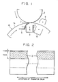
- Fig. 1 clearly shows a critical portion of the first embodiment of the present invention, i.e., a transfer device including the transfer drum 4 which is of the same type as that shown in Fig. 8 and which serves as a transfer member conveying means.
- the transfer drum 4 has a pair of end rings 4a and 4b made of a conductive material such as a metal, and a dielectric sheet 14 serving as the transfer member carrying means stretched over the open area between both end rings 4a, 4b.
- the dielectric sheet 14 is made of a suitable dielectric material such as polyvinylidene fluoride (PVdF) and has a thickness ranging between 70 and 200 ⁇ m, a dielectric constant ranging between 3.0 and 13.0 and a volumetric resistivity ranging between 109 and 1014 ⁇ cm.
- PVdF polyvinylidene fluoride
- the dielectric sheet 14 is fastened at its leading and trailing ends to the bridge portion 4c interconnecting two end rings 4a and 4b of the transfer drum 4.
- the transfer drum 4 has a diameter of 160 mm and is operated to rotate at a peripheral speed of 160 mm/sec.
- the process speed including the peripheral speed of the photosensitive drum 3 also is set to 160 mm/sec.
- the transfer corona discharger 7 has an opening of 19 mm wide through which discharge wires 6 are exposed.
- the distance between the ends of the discharge wires 6 and the outer peripheral surface of the photosensitive drum 3 as the image carrier is determined to be 10.5 mm, while the distance between the discharge wires 6 and the bottom surface of the shield plate of the transfer corona discharger 7is set to 16 mm.
- a resilient pressing member 1 is provided in a transfer section which is determined by the width of discharge from the transfer corona discharge, so as to extend substantially in the downstream direction as viewed in the direction of movement of the surface of the transfer drum 4.
- the pressing member 1 is made of a dielectric plastic film such as of polyethylene, polypropylene, polyester or polyethylene terephthalate, preferably having a volumetric resistivity not smaller than 1010 ⁇ cm and more preferably not smaller than 1014 ⁇ cm.
- the pressing member is extended over the entire area of the transfer section.
- a polyethylene terephthalate film is used as the pressing member 1.
- the pressing member 18 is preferably arranged such that it can press the dielectric sheet 14 onto the photosensitive drum 3 by its resiliency. It is also preferred that the end of the pressing member 1 adjacent the dielectric sheet 14 is located at a transfer position, more specifically, the position at which the contact between the transfer member P and the photosensitive drum 3 is ceased, a position at which the transfer member P starts to contact with the photosensitive drum 3 or the position where the distance between the transfer member P and the photosensitive drum is minimized.
- the thickness of the pressing member is preferably selected to range between 10 ⁇ m and 2 mm. Excellent results were obtained with pressing members of thicknesses ranging between 75 ⁇ m and 200 ⁇ m.
- the role of the pressing member 1 is merely to press the dielectric sheet 14 of the transfer drum, it will be possible to provide the pressing member 1 at a position downstream from the transfer corona discharger as viewed in the direction of movement of the surface of the transfer drum 4. Such an arrangement, however, will undesirably allow the transfer to be commenced before the transfer member P is brought into close contact with the photosensitive drum 3, thus reducing the effect of preventing local transfer failures. It is therefore preferred that the pressing member be located at a position upstream from the transfer corona discharger 7 as viewed in the direction of movement of the surface of the transfer drum 4, as in the illustrated embodiment.
- a sub-conductive member 2 is provided on the pressing member 1 as shown in Fig. 1.
- the sub-conductive member 2 is preferably arranged to oppose the transfer member carrying means.
- the sub-conductive member 2 is made of any suitable material which has a volumetric resistivity of 106 ⁇ cm to 1010 ⁇ cm, preferably 107 ⁇ cm to 109 ⁇ cm.
- the sub-conductive member 2 therefore, mat be formed by dispersing a low-resistance substance on a high-resistance substance or may be formed of a single material having a volumetric resistivity falling within the range specified above.
- the sub-conductive member 2 may be formed by applying a liquid-state material to the surface of the pressing member or by adhering a sheet-like member onto the pressing member 1.
- a video tape containing iron oxide powder can suitably be used as the sheet-type material of the sub-conductive member 2.
- the sub-conductive member 2 is preferably formed in the region where the discharge for the image transfer actually takes place.
- the sub-conductive member 2 is formed so as to extend over a width of 7 mm from a position which is 1 mm spaced from the end of the pressing member 1 contacting the dielectric sheet 14 of the transfer drum 4.
- the thickness of the sub-conductive portion is about 30 ⁇ m. It is not preferred to provide the sub-conductive member 12 in the vicinity of the extreme end of the pressing member 18 because in such a case the sub-conductive member 2 tends to be heavily damaged or worn as it is strongly rubbed by the dielectric sheet 14 and also by the bridge portion 4c of the transfer drum 4.
- the advantage of the present invention is significantly impaired. It is therefore not preferred to dispose the sub-conductive member 2 at a position more than 5 mm apart from the extreme end of the pressing member 1.
- the pressing member 1 is fixed to its supporting member at a portion thereof below a broken line in this Figure.
- the pressing member 1 exerts resiliency at its portion above the broken line.
- Electrostatic latent images formed on the photosensitive drum 3 charged negatively were inversely developed to form a multi-color toner image with toners having mean toner particle sizes of about 12 ⁇ m.
- the toners used in the test was formed from a resin particle mixed with coloring agents and also with trace amounts of agents which were added for the purpose of improving charge-controllability and lubricating performance.
- the toners thus formed were negatively charged with carrier particles in the developing units.
- the multi-color toner image was transferred to a transfer member by the transfer device of the type described before.
- the transfer material was then separated from the transfer drum 4 and sent to a fixing device where the multi-color toner image was fixed to the transfer material.
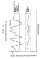
- the surface potential of the pressing member in the region adjacent the portion pressing the dielectric sheet was measured and compared with the surface potential as observed when a conventional pressing member devoid of the sub-conductive member was used.
- the results are shown in Fig. 3. From this Figure, it will be seen that both the level of the surface potential and the amplitude or magnitude of fluctuation of the surface potential are reduced when the pressing member 1 of the invention with the sub-conductive member 2 is used, as compared with the case where the conventional pressing member having no sub-conductive member is used.
- the present inventors have conducted a further study on the mechanism of the image transfer and found that non-uniform transfer of image, i.e., is attributable to a large local fluctuation in the surface potential of the pressed portion of the dielectric sheet.
- the relationship between the occurrence of transfer irregularity and the surface potential of the dielectric sheet was examined in the conventional case where the pressing member having no sub-conductive member was used. It was confirmed that image transfer can be conducted in good manner when the surface potential falls within the range which is defined by two horizontal parallel solid lines shown in Fig. 3. It was also found that the magnitude of fluctuation of the surface potential produces a more significant influence on the transfer irregularity than the absolute value of the surface potential.
- two parallel broken lines define the range which is the same as the surface potential range shown by the two horizontal parallel solid lines mentioned above, i.e., the surface potential range which ensures good transfer if image with the conventional pressing member having no sub-conductive member. It will be seen that the surface potential observed when the pressing member having the sub-conductive member is maintained within this range, thus proving that image can be transferred in a good manner without irregularity. It was also confirmed that a reduction in the absolute value of the surface potential widens the range which is free from occurrence of transfer irregularity.
- both the absolute value of the surface potential and the magnitude of the surface potential fluctuation are reduced. This is attributed to the following reasons.
- the sub-conductive member 2 on the pressing member 1 has a volumetric resistivity of about 108 ⁇ cm, so that it promotes discharge of electrostatic charges from the pressing member which is charged by the operation of the transfer corona discharger, as compared with the case where the pressing member is wholly made of, for example, a polyester resin.
- the surface potential of the pressing member 1 is maintained at levels lower than those obtained when the conventional pressing member having no sub-conductive member is used.
- the sub-conductive member 2 allows easier movement of the electrostatic charges, thus promoting distribution of the charges so as to contribute to the uniformalization of the surface potential.
- the pressing member 1 which is made of,for example, a polyester resin film, tends to exhibit a large local concentration of charges due to friction with the dielectric sheet 14 or the bridge portion 4c connecting both axial ring portions 4a,4b of the transfer drum 4.
- the level and magnitude of fluctuation of surface potential due to such frictional charging can also be reduced by virtue of the sub-conductive member 2 on the pressing member 1.
- the material of the conductive member i.e., the sub-conductive member used in this embodiment, may be a magnetite-type ferrite (FeO(Fe2O3) which exhibits a volumetric resistivity of 107 ⁇ cm to 1010 ⁇ cm.
- the conductive member 2 is provided on the surface of the pressing member opposite to the surface facing the transfer means, for the following reasons.
- the corona discharge produces a strong oxidizing atmosphere which contains ozone and nitrogen oxides.
- a material having a spinel structure e.g., a ferrite
- the volumetric resistivity of the ferrite is undesirably increased to a level exceeding 1011 ⁇ cm.
- the volumetric resistivity of the conductive member 2 is increased to a level substantially approximating that of the pressing member 1, thus extinguishing the effect produced by the conductive member.
- the conductive member 2 is provided on the side of the pressing member opposite to the transfer means including the transfer corona discharger.
- the present invention is effective also in the case where the image transfer is conducted for a plurality of times with progressively increased transfer voltages.
- Fig. 11 is an electric circuit diagram of a charging/discharging circuit formed by the pressing member, conductive member and the supporting member.
- a symbol R0 represents the resistance value of the conductive member, i.e.,the sub-conductive member
- R1 represents the resistance produced by the space of a distance l1 between the supporting member 5 and the sub-conductive member 2
- R2 represents the resistance formed by the space of a l2 between the supporting member 5 and the sub-conductive member 2.
- the resistance values of the resistances R1 and R2 are about 100 to 200 M ⁇ and about 70 to 150 M ⁇ , respectively.
- the present invention always produces a stable transfer electric field even when a high transfer voltages are repeatedly applied for superimposing toner images as in the case of a multi-color printing, whereby a multi-color image of an excellent quality is obtained without suffering from transfer irregularity.
- a material having a volumetric resistivity smaller than that of the sub-conductive member 2 used in the illustrated embodiment a material having a volumetric resistivity smaller than that of the sub-conductive member 2 used in the illustrated embodiment.
- the use of a material having a volumetric resistivity not greater than 106 ⁇ cm undesirably causes an instantaneous discharge of a large quantity of stored charges, so that the transfer electric field is excessively strengthened at local minor points, with the results that local transfer defects in the form of rice grains are generated in the transferred image.
- the sub-conductive member 2 provided on the pressing member 1 has a volumetric resistivity ranging between 106 ⁇ cm and 1010 ⁇ cm, preferably around 108 ⁇ cm, whereby a superior image quality is obtained by virtue of a uniform image transfer without suffering from transfer defect attributable to any local discharge.
- the transfer apparatus of the present invention offers a greater effect when the toner as the developing agent for developing the image on the photosensitive drum 3 has a particle size not greater than 10 ⁇ m, more specifically around 8 ⁇ m in terms of mean particle size.
- a detailed description will be given in this connection with specific reference to Fig. 4.
- toners of smaller particle sizes generally exhibit greater levels of affinity or adhesion to the photosensitive drum and, hence, generally inferior transferability. Consequently, the surface potential range which is free from transfer irregularity is narrowed, as will be realized from a comparison between the width between two horizontal parallel solid lines shown in Fig. 4 representing the surface potential range free from the transfer irregularity and that shown in Fig. 3.
- the present invention which employs the sub-conductive member 2 provided on the pressing member 18.
- the sub-conductive member 2 effectively reduces both the level of the surface potential and the magnitude of the fluctuation of the surface potential.
- Two horizontal parallel broken lines in Fig. 4 shows the surface potential range free from the transfer irregularity equal to that shown by the two parallel horizontal solid lines in the same Figure. It will be seen that, when the image transfer is conducted with the aid of the pressing member having the sub-conductive member thereon, the surface potential is maintained within the above-mentioned range free from transfer irregularity, thus offering good state of image transfer even when a finer toner is used. It will be understood that the present invention allows the use of a finer toner for attaining a higher quality of the image, without being accompanied by any transfer irregularity.
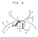
- the inventors conducted a further study and experiment and found that wear of the sub-conductive member 2 is suppressed so that the sub-conductive member 2 can have an extended life when this layer 2 is covered with an additional layer 111 of pressing member serving as a protective member, as shown in Fig. 9 which illustrates a second embodiment of the present invention.
- the protective member 111 is made of a film of polyethylene terephthalate having a thickness greater than that of the pressing member 1, e.g., 75 ⁇ m, and is provided in such a manner as to cover the sub-conductive member 2.
- the provision of the protective member 111 does never impede the aforementioned advantages of the present invention. Moreover, better results were obtained by virtue of the protective member 111 since it allows the sub-conductive member 19 to be located on the end extremity of the pressing member without any risk of wear and damage.
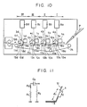
- the present invention can also be applied to a multi-color electrophotographic copying apparatus having four image forming units I to IV as shown in Fig. 10.
- the apparatus shown in Fig. 10 as a modification of the first embodiment of the present invention, has independent image forming units I to IV having photosensitive drums 3a to 3d and other components arranged around these drums 3a to 3d, including primary chargers 4a to 4d, exposure devices 8a to 8d, developing devices 1a to 1d, transfer chargers 10a to 10d, charge-removing dischargers 11a to 11d and 13a to 13d, and cleaners 12a to 12d.
- An endless conveyor 24 is disposed to extend through the image forming units I to IV at a position under the respective photosensitive drums.
- the image forming units I to IV are provided with pressing members 18a to 18d which press the endless conveyor belt 20 towards the respective photosensitive drums within the discharge coverages of the associated transfer dischargers 10a to 10d.
- Sub-conductive members 19a to 19d are provided on the respective transfer dischargers 10a to 10d.
- the sub-conductive members which are formed on the pressing members for pressing the endless conveyor belt towards the associated photosensitive drums, produce the same effect as that produced by the preceding embodiments, thus offering a better quality of the image.
- Figs. 12 and 13 show a third embodiment in which a conductive member 25 is provided inside the pressing member 26 which is an integral member having a volumetric resistivity of 1010 ⁇ cm or grater.
- the pressing member 26 In order to apply a moderate pressing force to the dielectric sheet 14 while eliminating any substantial influence on the transfer electric field, the pressing member 26 preferably has a thickness ranging between 10 ⁇ m and 2 mm. Very good results were obtained when the thickness ranged between 75 and 200 ⁇ m.
- the conductive member 25 may have a volumetric resistivity of 105 ⁇ cm or less.
- the conductive member 25 is formed from a metal foil having a thickness smaller than that of the pressing member 26.
- both longitudinal ends of the conductive member 25 are extended externally of the pressing member 26 so as to provide terminals 25X, 25Y for connection to grounded portions of the main part of the apparatus. These grounded portions are disposed such that the corona discharges for the image transfer do not directly act on these grounded portions.
- Grounding of the conductive member 25, however, is not essential, and substantially the same effect could be obtained even when the conductive member 25 was held in a floating condition.
- the first to third embodiments as described suffer from a common disadvantage in that a permanent strain of the pressing member is caused during a long use of the apparatus so that the pressing force is progressively decreased from the initial level, with the results that the quality of the image is degraded by presence of transfer irregularity and transfer defects after production of about 20,000 copies of A-4 size.
- FIGs. 17 to 19 are schematic sectional views of an essential portion of an electrophotographic copying apparatus showing particularly the positional relationship between the bridge portion 4c of the transfer drum 4. the transfer charger 7 and the pressing member 1. It will be understood that, when the pressing member 1 presses the dielectric sheet 14, a large force is applied to an end portion 1A of the pressing member 1 where the pressing member is fixed to the supporting member, as shown in Fig. 17. As the transfer drum 4 further rotates, the bridge portion 4c passes the transfer position where it contacts the pressing member 1 so as to further bend the pressing member 1 as shown in Fig.
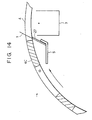
- Fig. 14 shows a fourth embodiment of the present invention which overcomes the above-described problem.
- the dielectric sheet has been detached from the transfer drum 4 for the purpose of simplification of explanation.
- a backup member 27 of a length smaller than the length of the pressing member 1 is attached to the side of the pressing member 1 adjacent the transfer charger 7.
- the pressing member 1 is made of a sheet of polyethylene terephthalate resin of 125 ⁇ m thick.
- the backup member 27 for urging the pressing member 1 into contact with the dielectric sheet 14 also is made of a sheet of polyethylene terephthalate resin of 100 ⁇ m thick. The backup member 27 is so arranged as not to contact the bridge portion 4c of the transfer drum 4.
- a test operation was conducted to examine the relationship between the number of A-4 size copies and change in the level of the pressing force exerted by the pressing member in the copying apparatus of the embodiment shown in Fig. 14.
- a similar test was conducted also with the apparatus of the first embodiment, and the results were compared with each other.
- two horizontal parallel lines indicate upper and lower limits of the pressing force to be exerted by the pressing member for attaining good transfer of the image without transfer irregularity and transfer failure.
- the pressing force is below the lower line indicating the lower limit of the pressing force, transfer defects are liable to occur due to a reduction in the transfer efficiency and transfer irregularity attributable to insufficient contact between the photosensitive drum and the transfer drum.
- Pressing force exceeding the level of the upper line indicative of the upper limit also tends to cause a degradation of the quality of the transferred image due to an irregular rotation of the transfer drum attributable to excessively large pressure of contact between the pressing member and the photosensitive drum.
- the pressing force of the pressing member has come down below the lower limit of the adequate pressing force, after production of about 20,000 copies.
- the pressing force was maintained within the range of the adequate pressing force even after production of 100,000 copies, by virtue of the backup member, as will be seen from Fig. 16.
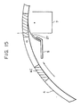
- the embodiment shown in Fig. 14 offers a remarkable improvement in the durability of the pressing member. The reasons of this remarkable improvement will be described with reference to Fig. 15.
- the pressing member 1, which is backed up by the backup member 27, is in contact with the bridge portion 4c of the transfer drum 4.
- the backup member 27 serves to distribute the force applied to the pressing member, thus eliminating any local concentration of the bending stress to the fixed end portion of the pressing member 1 and the portion of the same contacting a shield plate of the transfer charger 7.
- the bending force is uniformly distributed over the region backed up by the backup member 27 so that generation of permanent strain is suppressed, whereby the life of the pressing member is extended. This enables the image forming apparatus to operate stably with good quality of the transferred image for a longer time.
- the embodiment shown in Fig. 14 employs two sheets, i.e., the pressing member and the backup member. This, however, is not exclusive and three of more such sheets may be employed. In such a case, the above-described advantage can be brought about provided that at least one of these sheets has a free length greater than those of other sheets. The effect will be enhanced if these sheets are arranged such that at least one of these sheets kept out of contact with the bridge portion of the transfer drum.
- Fig. 14 can be combined with any of the preceding embodiments. Such a combination will enable the pressing member to maintain the adequate pressing force for a longer period, thus offering a great advantage in that the image forming apparatus can operate for longer time without suffering substantial degradation of the image quality.
Landscapes
- Physics & Mathematics (AREA)
- General Physics & Mathematics (AREA)
- Electrostatic Charge, Transfer And Separation In Electrography (AREA)
Applications Claiming Priority (8)
| Application Number | Priority Date | Filing Date | Title |
|---|---|---|---|
| JP138964/89 | 1989-05-31 | ||
| JP1138964A JP2614315B2 (ja) | 1989-05-31 | 1989-05-31 | 画像形成装置 |
| JP1138778A JP2623140B2 (ja) | 1989-05-31 | 1989-05-31 | 画像形成装置 |
| JP138778/89 | 1989-05-31 | ||
| JP138780/89 | 1989-05-31 | ||
| JP13878089A JP2623141B2 (ja) | 1989-05-31 | 1989-05-31 | 画像形成装置 |
| JP2139035A JPH0431885A (ja) | 1990-05-28 | 1990-05-28 | 画像形成装置 |
| JP139035/90 | 1990-05-28 |
Publications (2)
| Publication Number | Publication Date |
|---|---|
| EP0400996A1 true EP0400996A1 (de) | 1990-12-05 |
| EP0400996B1 EP0400996B1 (de) | 1994-05-11 |
Family
ID=27472173
Family Applications (1)
| Application Number | Title | Priority Date | Filing Date |
|---|---|---|---|
| EP90305888A Expired - Lifetime EP0400996B1 (de) | 1989-05-31 | 1990-05-30 | Bilderzeugungsgerät |
Country Status (3)
| Country | Link |
|---|---|
| US (1) | US5091751A (de) |
| EP (1) | EP0400996B1 (de) |
| DE (1) | DE69008772T2 (de) |
Cited By (7)
| Publication number | Priority date | Publication date | Assignee | Title |
|---|---|---|---|---|
| EP0507055A3 (en) * | 1991-03-30 | 1993-02-03 | Kabushiki Kaisha Toshiba | Image forming apparatus |
| EP0487046A3 (en) * | 1990-11-21 | 1993-03-03 | Canon Kabushiki Kaisha | Image forming apparatus |
| EP0551015A1 (de) * | 1992-01-09 | 1993-07-14 | Canon Kabushiki Kaisha | Bilderzeugungsgerät mit Tragvorrichtung für Übertragungsmaterial |
| EP0525785A3 (en) * | 1991-08-01 | 1993-08-04 | Canon Kabushiki Kaisha | Transfer sheet-carrying member and image forming apparatus |
| US5249021A (en) * | 1991-02-28 | 1993-09-28 | Canon Kabushiki Kaisha | Image forming apparatus having recording material carrying means |
| DE4291112C2 (de) * | 1991-04-12 | 1997-01-30 | Hitachi Ltd | Einrichtung zur elektrophotographischen Bildaufzeichnung |
| EP0604974A3 (de) * | 1992-12-29 | 1997-04-02 | Canon Kk | Bilderzeugungsgerät mit Übertragungsmaterialträger |
Families Citing this family (21)
| Publication number | Priority date | Publication date | Assignee | Title |
|---|---|---|---|---|
| JP2660939B2 (ja) * | 1990-10-11 | 1997-10-08 | キヤノン株式会社 | 画像形成装置 |
| JP2750026B2 (ja) * | 1990-10-13 | 1998-05-13 | キヤノン株式会社 | 記録材担持手段を有する画像形成装置 |
| US5172172A (en) * | 1991-02-28 | 1992-12-15 | Canon Kabushiki Kaisha | Image forming apparatus |
| JP3535528B2 (ja) * | 1991-03-04 | 2004-06-07 | キヤノン株式会社 | 画像形成装置 |
| JP3179168B2 (ja) * | 1992-01-30 | 2001-06-25 | キヤノン株式会社 | 転写材担持部材及び画像形成装置 |
| EP0573061B1 (de) * | 1992-06-05 | 2005-12-21 | Canon Kabushiki Kaisha | Bilderzeugungsgerät |
| JP3226629B2 (ja) * | 1992-09-29 | 2001-11-05 | キヤノン株式会社 | 画像形成装置 |
| US5640658A (en) * | 1992-09-30 | 1997-06-17 | Canon Kabushiki Kaisha | Image forming apparatus capable of forming image on both surfaces of recording material |
| EP0593072B1 (de) * | 1992-10-16 | 1999-09-01 | Canon Kabushiki Kaisha | Bilderzeugungsgerät |
| JPH0777879A (ja) * | 1993-09-07 | 1995-03-20 | Canon Inc | 画像形成装置 |
| JP3247237B2 (ja) * | 1994-01-12 | 2002-01-15 | キヤノン株式会社 | 画像形成装置 |
| US5568238A (en) * | 1995-11-20 | 1996-10-22 | Xerox Corporation | Transfer assist apparatus having a conductive blade member |
| US5613179A (en) * | 1995-11-21 | 1997-03-18 | Xerox Corporation | Force applying blade device exhibiting a reduced creep rate |
| US6253041B1 (en) | 1998-11-27 | 2001-06-26 | Canon Kabushiki Kaisha | Image forming apparatus |
| JP3728166B2 (ja) | 1999-02-12 | 2005-12-21 | キヤノン株式会社 | 画像形成装置 |
| JP3605007B2 (ja) | 1999-07-16 | 2004-12-22 | キヤノン株式会社 | 画像形成装置 |
| JP2007298543A (ja) * | 2006-04-27 | 2007-11-15 | Fuji Xerox Co Ltd | トナーカートリッジ |
| US7406284B2 (en) * | 2006-05-05 | 2008-07-29 | Infoprint Solutions Company, Llc | Apparatus for improving image fidelity on high-speed electrophotographic printing systems |
| US7587158B2 (en) * | 2006-09-29 | 2009-09-08 | Lexmark International Inc. | Second transfer area for an image forming device and methods of use |
| JP5436032B2 (ja) * | 2009-05-01 | 2014-03-05 | キヤノン株式会社 | 画像形成装置 |
| JP6150568B2 (ja) * | 2013-03-12 | 2017-06-21 | キヤノン株式会社 | 画像形成装置 |
Citations (5)
| Publication number | Priority date | Publication date | Assignee | Title |
|---|---|---|---|---|
| DE2558615A1 (de) * | 1974-12-28 | 1976-07-08 | Canon Kk | Bilduebertragungsvorrichtung |
| DE2702110A1 (de) * | 1976-01-19 | 1977-07-28 | Konishiroku Photo Ind | Bilduebertragungs-zusatzvorrichtung fuer ein elektrophotographisches kopiergeraet |
| DE2359331B2 (de) * | 1973-01-12 | 1977-08-04 | Xerox Corp, Rochester, N.Y. (V.St.A.) | Einrichtung zur elektrostatischen uebertragung eines auf einem elektrofotographischen aufzeichnungsmaterial befindlichen tonerbildes auf ein bildempfangsmaterial im durchlaufverfahren |
| US4114536A (en) * | 1976-08-26 | 1978-09-19 | Ricoh Co., Ltd. | Method of and apparatus for transfer printing a toner image |
| EP0298505A2 (de) * | 1987-07-09 | 1989-01-11 | Canon Kabushiki Kaisha | Bilderzeugungsgerät |
Family Cites Families (3)
| Publication number | Priority date | Publication date | Assignee | Title |
|---|---|---|---|---|
| JPS538146A (en) * | 1976-07-12 | 1978-01-25 | Canon Inc | Transfer mechanism |
| JPS59119373A (ja) * | 1982-12-27 | 1984-07-10 | Canon Inc | 画像形成装置 |
| US4851960A (en) * | 1986-12-15 | 1989-07-25 | Canon Kabushiki Kaisha | Charging device |
-
1990
- 1990-05-30 EP EP90305888A patent/EP0400996B1/de not_active Expired - Lifetime
- 1990-05-30 US US07/530,802 patent/US5091751A/en not_active Expired - Lifetime
- 1990-05-30 DE DE69008772T patent/DE69008772T2/de not_active Expired - Fee Related
Patent Citations (5)
| Publication number | Priority date | Publication date | Assignee | Title |
|---|---|---|---|---|
| DE2359331B2 (de) * | 1973-01-12 | 1977-08-04 | Xerox Corp, Rochester, N.Y. (V.St.A.) | Einrichtung zur elektrostatischen uebertragung eines auf einem elektrofotographischen aufzeichnungsmaterial befindlichen tonerbildes auf ein bildempfangsmaterial im durchlaufverfahren |
| DE2558615A1 (de) * | 1974-12-28 | 1976-07-08 | Canon Kk | Bilduebertragungsvorrichtung |
| DE2702110A1 (de) * | 1976-01-19 | 1977-07-28 | Konishiroku Photo Ind | Bilduebertragungs-zusatzvorrichtung fuer ein elektrophotographisches kopiergeraet |
| US4114536A (en) * | 1976-08-26 | 1978-09-19 | Ricoh Co., Ltd. | Method of and apparatus for transfer printing a toner image |
| EP0298505A2 (de) * | 1987-07-09 | 1989-01-11 | Canon Kabushiki Kaisha | Bilderzeugungsgerät |
Non-Patent Citations (1)
| Title |
|---|
| PATENT ABSTRACTS OF JAPAN * |
Cited By (10)
| Publication number | Priority date | Publication date | Assignee | Title |
|---|---|---|---|---|
| EP0487046A3 (en) * | 1990-11-21 | 1993-03-03 | Canon Kabushiki Kaisha | Image forming apparatus |
| US5249022A (en) * | 1990-11-21 | 1993-09-28 | Canon Kabushiki Kaisha | Image forming device having an electrically dielectric regulating member conductive transfer member and a disposed at a transfer station thereof |
| US5249021A (en) * | 1991-02-28 | 1993-09-28 | Canon Kabushiki Kaisha | Image forming apparatus having recording material carrying means |
| EP0507055A3 (en) * | 1991-03-30 | 1993-02-03 | Kabushiki Kaisha Toshiba | Image forming apparatus |
| DE4291112C2 (de) * | 1991-04-12 | 1997-01-30 | Hitachi Ltd | Einrichtung zur elektrophotographischen Bildaufzeichnung |
| EP0525785A3 (en) * | 1991-08-01 | 1993-08-04 | Canon Kabushiki Kaisha | Transfer sheet-carrying member and image forming apparatus |
| US5327200A (en) * | 1991-08-01 | 1994-07-05 | Canon Kabushiki Kaisha | Transfer sheet-carrying member and image forming apparatus |
| EP0551015A1 (de) * | 1992-01-09 | 1993-07-14 | Canon Kabushiki Kaisha | Bilderzeugungsgerät mit Tragvorrichtung für Übertragungsmaterial |
| US5594537A (en) * | 1992-01-09 | 1997-01-14 | Canon Kabushiki Kaisha | Image forming apparatus with transfer material support member |
| EP0604974A3 (de) * | 1992-12-29 | 1997-04-02 | Canon Kk | Bilderzeugungsgerät mit Übertragungsmaterialträger |
Also Published As
| Publication number | Publication date |
|---|---|
| US5091751A (en) | 1992-02-25 |
| DE69008772T2 (de) | 1994-09-08 |
| DE69008772D1 (de) | 1994-06-16 |
| EP0400996B1 (de) | 1994-05-11 |
Similar Documents
| Publication | Publication Date | Title |
|---|---|---|
| EP0400996B1 (de) | Bilderzeugungsgerät | |
| JP3516551B2 (ja) | 静電画像形成装置 | |
| EP0487046B1 (de) | Bilderzeugungsgerät | |
| US6301455B1 (en) | Charging member, charging device and image forming apparatus wherein deposition of magnetic particles to a member to be charged is effectively prevented | |
| US5081501A (en) | Image forming apparatus having transfer electrode | |
| EP0458273B1 (de) | Aufladevorrichtung, Bilderzeugungsgerät mit einer solchen Vorrichtung und von dem Bilderzeugungsgerät abnehmbare Arbeitseinheit | |
| EP0840175B1 (de) | Ein Bilderzeugungsgerät | |
| US7764917B2 (en) | Image forming apparatus including a photosensitive member, a cleaning blade, and a cleaning brush | |
| US5410390A (en) | Image forming apparatus having transfer material carrying member with specific resistance ratio | |
| JP3599187B2 (ja) | 画像形成装置 | |
| US7092659B2 (en) | Discharge methods and systems in electrophotography | |
| US5313359A (en) | Excessive current preventing device for the contact charging of a photosensitive layer | |
| JP3486520B2 (ja) | 画像形成装置 | |
| JP3397593B2 (ja) | 画像形成装置 | |
| JPH04186387A (ja) | 画像形成装置 | |
| JPH06222649A (ja) | 帯電装置 | |
| JPH09329975A (ja) | 画像形成装置 | |
| JP2785411B2 (ja) | 接触帯電装置 | |
| JP2004117884A (ja) | 画像形成装置 | |
| JPH06161296A (ja) | 画像形成装置 | |
| JPH0431885A (ja) | 画像形成装置 | |
| JPH04208969A (ja) | 転写装置 | |
| JPH06175510A (ja) | 画像形成方法及びその装置 | |
| JP2003177611A (ja) | 画像形成装置 | |
| HK1014053B (en) | Charging device and charging apparatus |
Legal Events
| Date | Code | Title | Description |
|---|---|---|---|
| PUAI | Public reference made under article 153(3) epc to a published international application that has entered the european phase |
Free format text: ORIGINAL CODE: 0009012 |
|
| AK | Designated contracting states |
Kind code of ref document: A1 Designated state(s): DE FR GB IT |
|
| 17P | Request for examination filed |
Effective date: 19901231 |
|
| 17Q | First examination report despatched |
Effective date: 19921203 |
|
| GRAA | (expected) grant |
Free format text: ORIGINAL CODE: 0009210 |
|
| AK | Designated contracting states |
Kind code of ref document: B1 Designated state(s): DE FR GB IT |
|
| REF | Corresponds to: |
Ref document number: 69008772 Country of ref document: DE Date of ref document: 19940616 |
|
| ET | Fr: translation filed | ||
| ITF | It: translation for a ep patent filed | ||
| PLBE | No opposition filed within time limit |
Free format text: ORIGINAL CODE: 0009261 |
|
| STAA | Information on the status of an ep patent application or granted ep patent |
Free format text: STATUS: NO OPPOSITION FILED WITHIN TIME LIMIT |
|
| 26N | No opposition filed | ||
| ITTA | It: last paid annual fee | ||
| REG | Reference to a national code |
Ref country code: GB Ref legal event code: IF02 |
|
| PGFP | Annual fee paid to national office [announced via postgrant information from national office to epo] |
Ref country code: GB Payment date: 20060517 Year of fee payment: 17 |
|
| PGFP | Annual fee paid to national office [announced via postgrant information from national office to epo] |
Ref country code: FR Payment date: 20060518 Year of fee payment: 17 |
|
| PGFP | Annual fee paid to national office [announced via postgrant information from national office to epo] |
Ref country code: IT Payment date: 20060531 Year of fee payment: 17 |
|
| PGFP | Annual fee paid to national office [announced via postgrant information from national office to epo] |
Ref country code: DE Payment date: 20060726 Year of fee payment: 17 |
|
| GBPC | Gb: european patent ceased through non-payment of renewal fee |
Effective date: 20070530 |
|
| REG | Reference to a national code |
Ref country code: FR Ref legal event code: ST Effective date: 20080131 |
|
| PG25 | Lapsed in a contracting state [announced via postgrant information from national office to epo] |
Ref country code: DE Free format text: LAPSE BECAUSE OF NON-PAYMENT OF DUE FEES Effective date: 20071201 |
|
| PG25 | Lapsed in a contracting state [announced via postgrant information from national office to epo] |
Ref country code: GB Free format text: LAPSE BECAUSE OF NON-PAYMENT OF DUE FEES Effective date: 20070530 |
|
| PG25 | Lapsed in a contracting state [announced via postgrant information from national office to epo] |
Ref country code: FR Free format text: LAPSE BECAUSE OF NON-PAYMENT OF DUE FEES Effective date: 20070531 |
|
| PG25 | Lapsed in a contracting state [announced via postgrant information from national office to epo] |
Ref country code: IT Free format text: LAPSE BECAUSE OF NON-PAYMENT OF DUE FEES Effective date: 20070530 |