EP0401016B1 - Blut/Gas-Trennungs- und Fliesssystem - Google Patents
Blut/Gas-Trennungs- und Fliesssystem Download PDFInfo
- Publication number
- EP0401016B1 EP0401016B1 EP90305935A EP90305935A EP0401016B1 EP 0401016 B1 EP0401016 B1 EP 0401016B1 EP 90305935 A EP90305935 A EP 90305935A EP 90305935 A EP90305935 A EP 90305935A EP 0401016 B1 EP0401016 B1 EP 0401016B1
- Authority
- EP
- European Patent Office
- Prior art keywords
- reservoir
- blood
- compartment
- bag
- inlet port
- Prior art date
- Legal status (The legal status is an assumption and is not a legal conclusion. Google has not performed a legal analysis and makes no representation as to the accuracy of the status listed.)
- Expired - Lifetime
Links
- 210000004369 blood Anatomy 0.000 title claims description 132
- 239000008280 blood Substances 0.000 title claims description 132
- 239000013530 defoamer Substances 0.000 claims description 24
- 239000000463 material Substances 0.000 claims description 22
- 230000036765 blood level Effects 0.000 claims description 20
- 239000002518 antifoaming agent Substances 0.000 claims description 12
- 230000017531 blood circulation Effects 0.000 claims description 11
- 238000007789 sealing Methods 0.000 claims description 4
- 230000005484 gravity Effects 0.000 claims description 3
- 229920002635 polyurethane Polymers 0.000 claims description 2
- 239000004814 polyurethane Substances 0.000 claims description 2
- 230000003254 anti-foaming effect Effects 0.000 claims 1
- 239000006260 foam Substances 0.000 description 15
- 230000008901 benefit Effects 0.000 description 11
- 239000011248 coating agent Substances 0.000 description 9
- 238000000576 coating method Methods 0.000 description 9
- ORQBXQOJMQIAOY-UHFFFAOYSA-N nobelium Chemical compound [No] ORQBXQOJMQIAOY-UHFFFAOYSA-N 0.000 description 9
- 229920001296 polysiloxane Polymers 0.000 description 8
- 239000000126 substance Substances 0.000 description 8
- 239000012528 membrane Substances 0.000 description 7
- 239000012503 blood component Substances 0.000 description 6
- 239000010410 layer Substances 0.000 description 6
- 238000002156 mixing Methods 0.000 description 6
- 230000037361 pathway Effects 0.000 description 5
- 230000006378 damage Effects 0.000 description 4
- 238000013461 design Methods 0.000 description 3
- 238000000034 method Methods 0.000 description 3
- 239000000203 mixture Substances 0.000 description 3
- 238000001356 surgical procedure Methods 0.000 description 3
- 238000011144 upstream manufacturing Methods 0.000 description 3
- 229920005830 Polyurethane Foam Polymers 0.000 description 2
- 230000001627 detrimental effect Effects 0.000 description 2
- 238000001914 filtration Methods 0.000 description 2
- 239000012530 fluid Substances 0.000 description 2
- 239000012634 fragment Substances 0.000 description 2
- 238000005259 measurement Methods 0.000 description 2
- 230000007246 mechanism Effects 0.000 description 2
- 238000006213 oxygenation reaction Methods 0.000 description 2
- 239000011496 polyurethane foam Substances 0.000 description 2
- 230000008569 process Effects 0.000 description 2
- 238000003860 storage Methods 0.000 description 2
- KJLPSBMDOIVXSN-UHFFFAOYSA-N 4-[4-[2-[4-(3,4-dicarboxyphenoxy)phenyl]propan-2-yl]phenoxy]phthalic acid Chemical compound C=1C=C(OC=2C=C(C(C(O)=O)=CC=2)C(O)=O)C=CC=1C(C)(C)C(C=C1)=CC=C1OC1=CC=C(C(O)=O)C(C(O)=O)=C1 KJLPSBMDOIVXSN-UHFFFAOYSA-N 0.000 description 1
- 206010001526 Air embolism Diseases 0.000 description 1
- JOYRKODLDBILNP-UHFFFAOYSA-N Ethyl urethane Chemical compound CCOC(N)=O JOYRKODLDBILNP-UHFFFAOYSA-N 0.000 description 1
- 206010018910 Haemolysis Diseases 0.000 description 1
- 241000238367 Mya arenaria Species 0.000 description 1
- 208000027418 Wounds and injury Diseases 0.000 description 1
- 230000009471 action Effects 0.000 description 1
- 230000004913 activation Effects 0.000 description 1
- 239000000560 biocompatible material Substances 0.000 description 1
- 230000015572 biosynthetic process Effects 0.000 description 1
- 210000000988 bone and bone Anatomy 0.000 description 1
- 230000015556 catabolic process Effects 0.000 description 1
- 230000004087 circulation Effects 0.000 description 1
- 239000000306 component Substances 0.000 description 1
- 150000001875 compounds Chemical class 0.000 description 1
- 238000004925 denaturation Methods 0.000 description 1
- 230000036425 denaturation Effects 0.000 description 1
- 210000003743 erythrocyte Anatomy 0.000 description 1
- 238000002618 extracorporeal membrane oxygenation Methods 0.000 description 1
- 239000000835 fiber Substances 0.000 description 1
- 230000008588 hemolysis Effects 0.000 description 1
- 208000014674 injury Diseases 0.000 description 1
- 230000007774 longterm Effects 0.000 description 1
- 210000004072 lung Anatomy 0.000 description 1
- 230000004048 modification Effects 0.000 description 1
- 238000012986 modification Methods 0.000 description 1
- 229920000728 polyester Polymers 0.000 description 1
- 239000004800 polyvinyl chloride Substances 0.000 description 1
- 230000037452 priming Effects 0.000 description 1
- 102000004169 proteins and genes Human genes 0.000 description 1
- 108090000623 proteins and genes Proteins 0.000 description 1
- 238000005086 pumping Methods 0.000 description 1
- 230000009467 reduction Effects 0.000 description 1
- 230000000630 rising effect Effects 0.000 description 1
- 238000000926 separation method Methods 0.000 description 1
- 239000002356 single layer Substances 0.000 description 1
- 239000007787 solid Substances 0.000 description 1
- 210000001519 tissue Anatomy 0.000 description 1
- 238000012546 transfer Methods 0.000 description 1
- 230000002792 vascular Effects 0.000 description 1
- 238000011179 visual inspection Methods 0.000 description 1
Images


Classifications
-
- A—HUMAN NECESSITIES
- A61—MEDICAL OR VETERINARY SCIENCE; HYGIENE
- A61M—DEVICES FOR INTRODUCING MEDIA INTO, OR ONTO, THE BODY; DEVICES FOR TRANSDUCING BODY MEDIA OR FOR TAKING MEDIA FROM THE BODY; DEVICES FOR PRODUCING OR ENDING SLEEP OR STUPOR
- A61M1/00—Suction or pumping devices for medical purposes; Devices for carrying-off, for treatment of, or for carrying-over, body-liquids; Drainage systems
- A61M1/36—Other treatment of blood in a by-pass of the natural circulatory system, e.g. temperature adaptation, irradiation ; Extra-corporeal blood circuits
- A61M1/3621—Extra-corporeal blood circuits
- A61M1/3627—Degassing devices; Buffer reservoirs; Drip chambers; Blood filters
-
- A—HUMAN NECESSITIES
- A61—MEDICAL OR VETERINARY SCIENCE; HYGIENE
- A61M—DEVICES FOR INTRODUCING MEDIA INTO, OR ONTO, THE BODY; DEVICES FOR TRANSDUCING BODY MEDIA OR FOR TAKING MEDIA FROM THE BODY; DEVICES FOR PRODUCING OR ENDING SLEEP OR STUPOR
- A61M1/00—Suction or pumping devices for medical purposes; Devices for carrying-off, for treatment of, or for carrying-over, body-liquids; Drainage systems
- A61M1/14—Dialysis systems; Artificial kidneys; Blood oxygenators ; Reciprocating systems for treatment of body fluids, e.g. single needle systems for hemofiltration or pheresis
- A61M1/32—Oxygenators without membranes
- A61M1/322—Antifoam; Defoaming
- A61M1/325—Surfactant coating; Improving wettability
-
- A—HUMAN NECESSITIES
- A61—MEDICAL OR VETERINARY SCIENCE; HYGIENE
- A61M—DEVICES FOR INTRODUCING MEDIA INTO, OR ONTO, THE BODY; DEVICES FOR TRANSDUCING BODY MEDIA OR FOR TAKING MEDIA FROM THE BODY; DEVICES FOR PRODUCING OR ENDING SLEEP OR STUPOR
- A61M1/00—Suction or pumping devices for medical purposes; Devices for carrying-off, for treatment of, or for carrying-over, body-liquids; Drainage systems
- A61M1/36—Other treatment of blood in a by-pass of the natural circulatory system, e.g. temperature adaptation, irradiation ; Extra-corporeal blood circuits
- A61M1/3621—Extra-corporeal blood circuits
- A61M1/3627—Degassing devices; Buffer reservoirs; Drip chambers; Blood filters
- A61M1/3632—Combined venous-cardiotomy reservoirs
-
- Y—GENERAL TAGGING OF NEW TECHNOLOGICAL DEVELOPMENTS; GENERAL TAGGING OF CROSS-SECTIONAL TECHNOLOGIES SPANNING OVER SEVERAL SECTIONS OF THE IPC; TECHNICAL SUBJECTS COVERED BY FORMER USPC CROSS-REFERENCE ART COLLECTIONS [XRACs] AND DIGESTS
- Y10—TECHNICAL SUBJECTS COVERED BY FORMER USPC
- Y10S—TECHNICAL SUBJECTS COVERED BY FORMER USPC CROSS-REFERENCE ART COLLECTIONS [XRACs] AND DIGESTS
- Y10S128/00—Surgery
- Y10S128/03—Heart-lung
Definitions
- the present invention is concerned with blood reservoirs, and in particular venous and cardiotomy blood reservoirs.
- Extracorporeal circuits generally include devices for performing various tasks on the blood, e.g. oxygenation, filtration, and storage. Other procedures requiring the routing of blood through an extracorporeal circuit include extracorporeal membrane oxygenation (long term support) and autotransfusion.
- Extracorporeal circuits are typically set up by an individual known as a perfusionist.
- the perfusionist controls the rate of blood flow and operates the various devices connected in the circuit.
- Extracorporeal circuits generally include oxygenators, heat exchangers, and filters, which are interconnected by surgical tubing. These circuits also include reservoirs.
- a blood reservoir is an enclosure into which blood is temporarily stored. The storage of blood in reservoirs allows regulation of the patient's blood volume and pressure.
- reservoirs also include various elements to filter and defoam the blood.
- a first type of reservoir is one which is formed from a generally flexible bag or container. Blood will expand this type of reservoir as it enters the reservoir. The air to blood interface is limited by the lack of empty space in the reservoir prior to filling with blood. Generally such reservoirs are sealed from the external environment. Closed reservoirs have numerous advantages. Such reservoirs isolate the blood from air thus limiting the extent of the blood to air interface which is detrimental to blood components. Flexible containers collapse and expand as the quantity of blood varies without delivering large quantities of air downstream into the extracorporeal circuit. This reduces potential injury to the patient from air embolism, particularly when all of the blood is removed from the reservoir.
- closed reservoirs One disadvantage with closed reservoirs is the inability to separate gross amounts of incoming air. The separation of small amounts of air from the blood is also difficult with closed reservoirs absent screen filters. It is also difficult to remove any entrapped air from the reservoir without physically compressing the bag, or by sucking or pumping the air out of the bag with a syringe or similar device.
- a second type of reservoir is known as an open reservoir, and is formed from a rigid or hardshell container.
- the reservoir is filled with air which is pushed out by the entering blood.
- air is removed during the priming process, but a small volume of the reservoir remains filled with air during the operation of the reservoir. This provides for an air to blood interface, which as stated may lead to the damage of various blood components.
- open reservoirs One major advantage with open reservoirs is the establishment of the air to blood interface. Any air present in the incoming blood normally rises upwards through the blood passing across the blood to air interface. Such reservoirs typically include filters and defoaming elements which further enhance the release of entrapped gas across the blood to air interface. The released air is vented to atmosphere.
- open reservoirs allow for a precise measurement of the blood volume. That is, unlike the expanding and contracting closed reservoirs, open hardshell reservoirs allow for visual inspection of the quantity of blood flowing through the reservoir. By providing the hardshell reservoir with visually readable volume markings the precise amount of blood can be ascertained during the surgical procedure.
- Open reservoirs also tend to impose a lower back pressure on the extracorporeal circuit. That is, blood flow through the reservoir will not increase the back pressure in the upstream portion of the circuit. Closed reservoirs induce a greater back pressure in the upstream portion of the circuit which may increase the amount of blood forced into the heart.
- Examples of flexible shell reservoirs are disclosed in many of the above patent references, while examples of hardshell reservoirs are found in some commercially available oxygenators, such as the BCM-7, a product manufactured and sold by the Baxter Healthcare Corporation, Deerfield, Illinois, Capiox E, an oxygenator sold by Terumo Corporation, Tokyo, Japan; and the CML, an oxygenator sold by Cobe Corporation, Boulder, Colorado.
- BCM-7 a product manufactured and sold by the Baxter Healthcare Corporation, Deerfield, Illinois
- Capiox E an oxygenator sold by Terumo Corporation, Tokyo, Japan
- CML an oxygenator sold by Cobe Corporation, Boulder, Colorado.
- Blood passing through an extracorporeal circuit will usually entrap smaller air bubbles which normally will not pass through the air to blood interface.
- Some reservoirs have been designed to promote the breakdown of these smaller gas bubbles by incorporating screens in the blood pathway. For examples of such reservoirs see US-A-4,493,705, US-A-4,734,269, These reservoirs include 100 to 250 microns and 50 to 300 microns, respectively.
- Screens have also been positioned in filtering bags. These bags are usually positioned at the upstream end of extracorporeal circuits, and filter out denatured blood components. Entrapped gas bubbles would be broken down passing through this filter bag assembly.
- An example of such a bag is disclosed in US-A-4,035,304.
- Foam is highly undesirable. While the foam may be merely removed from the circuit, it is the usual practice to separate any blood from the foam first. This is usually accomplished by passing the foam through a porous element which is at least partially coated with a defoaming substance, such as silicone antifoam.
- Reservoirs have been designed to include fiber or equivalent elements which are coated with this antifoam material. Silicone antifoam or a derivative compound, breaks foam down into blood and gas. The gas is usually vented to the environment.
- An example of such a reservoir is seen in US-A-4,466,888,.
- US-A-4705497 discloses a blood reservoir comprising a hardshell housing having an inlet and outlet, a plurality of compartments and a defoaming member coated with silicone though which blood passes when flowing from the inlet to the outlet.
- silicone antifoam or equivalent substance
- This material can become dislodged and shed into the blood.
- the shed antifoam material can become lodged in the patient's vascular system disrupting blood flow.
- Some researchers have suggested a mechanism for limiting the potential exposure of blood with silicone antifoam.
- a reservoir in combination with an oxygenator, is disclosed in US-A-5039486.
- This application and EP-A-0253 467 disclose a reservoir having a defoaming material generally positioned above the maximum blood level. As stated in this application, the positioning of the defoaming material above this maximum blood level reduces the potential contact between the blood and the material.
- the present invention overcomes the above discussed disadvantages by providing a reservoir comprising a hardshell housing with a flexible bag therein, giving the benefits of both hard and flexible shells.
- the reservoir includes a hardshell housing which defines at least one blood compartment.
- the flexible bag is fixed in this compartment, and is connected to the blood inlet.
- the compartment remain substantially open to the atmosphere.
- the first end of the bag is formed with the microporous screen situated in the hardshell to lie partially below a minimum blood level.
- the second bag end is formed to remain substantially open, and is positioned to lie above a maximum blood level in the hard shell.
- the defoamer means comprises a porous body or mat positioned at least partially in the bag second end. This body or mat is partially coated with a defoaming substance.
- the blood entering the reservoir flows into and expands the flexible bag.
- the blood flows downward through and out the microporous screen in the lower end.
- the placement of the lower end below the minimum blood level ensures that blood exiting the screen will not excessively mix with any air.
- Foam entering the bag rises upward and is brought into contact with the defoaming material coated porous body.
- the placement of this body above the maximum blood level reduces the potential of contact between the blood and defoaming substance.
- the reservoir thus possesses the advantages of a flexible shell, while retaining the advantages of a hardshell.
- the reservoir includes two separate blood reservoir compartments.
- One compartment is formed as described above and functions as a venous reservoir.
- a second compartment functions as a cardiotomy reservoir.
- This reservoir is situated above the venous reservoir to allow for gravity flow from the cardiotomy to venous reservoirs.
- This latter compartment includes inlet and outlet ports, and a multilayered filter assembly through which passes the blood.
- This filter assembly includes a defoaming substance coated body or mat which is surrounded by a microporous filter. This assembly breaks down both small air bubbles and foam.
- the present invention is directed to open reservoirs, and specifically to open venous reservoirs.
- the venous reservoir is incorporated in a housing also having a cardiotomy reservoir.
- the reservoir provides the benefits of both hard and soft shell reservoirs by mounting a flexible bag in a hardshell.
- the bags flexibility ensures that the blood does not excessively mix with air. This aspect is provided by designing the flexible bag so that the blood is directed downward through a lower microscreen portion that is positioned to discharge the blood partially below the minimum blood level in the reservoir.
- the flexible bag is further designed to include a defoamer coated membrane positioned above the maximum blood level in the reservoir.
- minimum blood level it is meant the lowest level in the reservoir to which the blood will normally rise under normal blood flow and operating conditions for the particular reservoir.
- maximum blood level it is meant the highest level in the reservoir to which the blood will normally rise under normal blood flow and operating conditions for the particular reservoir.
- the importance of providing for the downward flow of blood out through the screen below the minimum blood level is to minimize the contact between flowing blood and air.
- the turbulence caused by the blood flowing out from the screen would, if the screen is exposed to the air, cause a mixing action between the blood and air. This is an unwanted occurrence.
- the positioning of the defoamer coated membrane above the maximum blood level reduces the potential of contact between the blood and the defoamer coating.
- the positioning of defoamer coating above the maximum blood level is more fully described in US-A-5039486, with the disclosure pertaining to the positioning of defoaming substances above the maximum blood level being incorporated herein by reference.
- the reservoir is useful as a venous or cardiotomy blood reservoir, and may have any suitable shape or configuration.
- the invention will be described with reference to a venous reservoir upon which is positioned a cardiotomy reservoir.
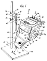
- a venous and cardiotomy reservoir assembly is seen generally at 10.
- the venous and cardiotomy reservoir assembly 10 is seen mounted upon a stand 12.
- Stand 12 includes a base portion 14 up from which extends a rod 16.
- the stand 12 further includes an arm assembly 18.
- the arm assembly 18 is formed to allow the reservoir assembly 10 to be positioned by the perfusionist at any desired height.
- Venous and cardiotomy reservoir assembly 10 is formed to be releasably mounted upon the arm assembly 18, with assembly 18 being formed to slide and lock down upon the rod 16.
- Arm assembly 18 is formed from an L-shaped member 20.
- One side of member 20 includes two upwardly extending posts 22 and 24. These posts 22 and 24 are fixed to the member 20 to be snuggly positioned at opposite sides of the assembly 18.
- the posts 22 and 24 are dimensioned to slide in respective guides 26 and 28 formed on the side walls of the assembly 18. In this arrangement the reservoir assembly 10 is easily mounted to the arm assembly 18.
- the arm assembly 18 is mounted to the L-shaped member 20 by two brackets 30 and 32.
- the two brackets 30 and 32 are formed with apertures 31 and 33 which slidingly fit about the member 20.
- Each bracket 30 and 32 also includes a slot 34 and 36, respectively. These slots 34 and 36 fit about the rod 16. Tightening screws 38 and 40 are threadably fit through the brackets 30 and 32 to engage and tighten down onto the rod 16.
- the reservoir assembly 10 includes two separate reservoirs, cardiotomy reservoir and venous reservoir seen generally at 42 and 44, respectively.
- the cardiotomy reservoir 42 is formed to fit atop the venous reservoir 44. It should be noted that the two reservoirs 42 and 44 may be formed as a single integral unit, or as two completely separate devices.
- Cardiotomy reservoir 42 includes multiple inlet ports 46. These ports 46 direct blood through a filter assembly seen generally at 48. Blood passing through the filter assembly 48 will fill the lower portion of the reservoir 42, seen generally at 52, which is formed with a well shaped region 110. As seen in Figure 1, this portion of the reservoir 42 includes a gradient scale 54. The gradient scale 54 allows the perfusionist to determine the quantity of blood in the reservoir 42. Blood exits this reservoir 42 through outlet port 50.
- Venous reservoir 44 includes a single inlet port 56 and a single outlet port 58.
- a flexible bag 60 is fixed in the venous reservoir 44 to a plate 62.
- This bag 60 includes a lower end 64 fitted with a microporous screen 66.
- the screen 66 has a porosity of from about forty to about two hundred microns, preferably one hundred microns. The small openings of the screen 66 ensure that small gas bubbles will not pass through the screen.
- the opposite other end, not seen in Figure 1, of the bag 60 is fitted with a porous element, also not seen in Figure 1.
- the porous element is a foamed polyurethane structure.
- the desired porosity of this porous element is from about four hundred to about eighteen hundred microns.
- At least part of the porous element is coated with a defoaming substance, usually silicone antifoam.
- Connector assembly 70 is mounted to the inlet port 56 and includes two tube connection stubs 72 and 74.
- the inlet port 56 is actually fitted into the side of the flexible bag 60. Blood enters the flexible bag 60 through the inlet port 56.
- the connector assembly 70 functions to deliver venous blood from the patient, via the tube 68, and cardiotomy blood from the cardiotomy reservoir 42, via another flexible tube 76 to the flexible bag 60 mounted in the venous reservoir 44.
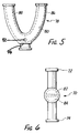
- the connector assembly 70 is seen in greater detail in Figure 6. This assembly 70 is coupled directly onto the inlet port 56.
- the assembly 70 defines a fluid pathway by an internal chamber, seen in phantom at 82.
- This chamber 82 is subdivided into two chambers by an internal wall, seen in phantom at 84. One half of the divided chamber 82 communicates with stub 72, while the other half with stub 74.
- the flexible tube 76 is further coupled to one arm 86 of a Y-connector 78, seen in Figure 5.
- the Y-connector 78 includes a second arm 88 coupled to a further flexible tube 90, which is coupled to the outlet port 50 of the cardiotomy reservoir 42.
- Y-shaped connector 78 further includes two access ports 92 and 94. These ports 92 and 94 allow either for the withdrawal of blood or access into the blood pathway by the connection of various devices to one of these ports.
- the Y-connector 78 is formed with an internal fluid pathway 80. This pathway 80 is generally Y-shaped.
- the Y-connector 78 is coupled to the flexible tubes 90 and 76 to be positioned at an angle to impede the passage of gas.
- the purpose of providing the Y-shaped connector 78 is to limit the ability of gas passing through any of the tubes from entering the venous reservoir 44.
- the positioning of the cardiotomoy reservoir 42 above the venous reservoir 44 allows for gravity flow.
- the use of the flexible tubing to interconnect the outlet ports of the cardiotomy reservoir 42 to the inlet ports of the venous reservoir 44 provides a mechanism for interrupting and controlling the flow of blood between the reservoirs 42 and 44. Blood flow to the venous reservoir 44 can be interrupted by clamping off the associated flexible tubings 90 or 76. This allows for control of the flow of cardiotomy blood to the venous reservoir 44.
- the reservoir assembly 10, and specifically reservoir 44 is formed with hooks, one of which is seen generally at 96. These hooks 96 are disposed at the lower underside of the reservoir 44. An oxygenator of the type more fully described in US-A-5120501, may be hung from these hooks 96. The outlet port 58 of the reservoir 44 may then be coupled to the inlet port of the oxygenator, not shown, to provide for transfer of the blood to the oxygenator.
- the reservoir assembly 10 includes two separate reservoirs, venous reservoir 44 and cardiotomy reservoir 42. These reservoirs 42 and 44 may either be integrally formed, or as illustrated, two separate housings assembled together.
- the cardiotomy reservoir 42 is situated on top of the venous reservoir 44.
- the cardiotomy reservoir 42 contains the cardiotomy filter assembly 48 which is situated in a portion of the internal chamber defined in the cardiotomy reservoir 42. This internal chamber, seen generally at 98, is accessed via the cardiotomy inlet ports 46. Blood entering through these ports 46 travels first through the cardiotomy filter assembly 48 and then temporarily accumulates in the internal chamber 98.
- the cardiotomy filter assembly 48 includes a porous filter element 100, a defoamer element 102, and a grid housing 104.
- the grid housing 104 is fixed to the cardiotomy filter assembly 48 to hang downward in the internal chamber 98.
- the defoamer element 102 and porous filter element 100 are respectively secured about the grid housing 104.
- the defoamer element 102 and porous filter membrane 100 are fixed about the grid housing 104 by a strap or band.
- This grid housing 104 defines an internal region, seen generally at 106, into which blood enters from the cardiotomy inlet ports 46. Numerous openings 108 are formed in the grid housing 104 through which blood passes into the defoamer element 102. Blood will then pass through the defoamer element 102 and then the porous filter element 100.
- the defoamer element 102 is any suitable biocompatible material, typically a porous polyurethane foam.
- the porosity of this material is generally in the range of from about four hundred to about eighteen hundred microns.
- Cardiotomy blood typically contains blood components, bone and tissue fragments, entrapped gas bubbles and foam, which is a mixture of blood and gas bubbles.
- a defoamer coating is applied to the defoamer membrane 102. This defoaming coating, not shown, is usually silicone antifoam.
- the blood components and fragments become entrapped within the defoamer element 102. Larger gas bubbles are broken down as the blood passes through the defoamer element 102. Foam passing through the defoamer element 102 is at least partially broken down into gas and blood.
- the porous filter element 100 is generally prepared from a polyester felt material, and is mounted about the defoamer filter 102.
- Blood exiting the porous filter membrane 100 travels down into a well 110 formed at the bottom of the cardiotomy reservoir 42.
- the cardiotomy outlet port 50 communicates with this well 110.
- the cardiotomy outlet port 50 is coupled through various tubes and connectors to the inlet port 56 of the venous reservoir 44.
- the arrangement of these various tubes and connectors, and particularly the design of Y-connector 78 minimizes the passage of gas bubbles into the venous reservoir 44.
- the inlet port 56 is connected directly into the flexible bag 60, which is mounted to the bag support plate 62 in the venous reservoir 44.
- the bag is sealed below and partially around the inlet port 56 as seen in Figure 4 at 55.
- This seal 55 which is generally linear in form, inhibits the backflow of air or blood through the inlet port 56.
- An illustration of a preferred design for the flexible bag 60 is seen in Figure 4.
- Flexible bag 60 is an elongated two walled structure formed by sealing the side edges of the two overlapping sheets of flexible material forming the flexible bag 60.
- the material from which the flexible bag 60 may be formed includes, polyvinyl chloride (PVC) and urethane.
- PVC polyvinyl chloride
- the flexible bag 60 is further formed with an open slot 114.
- This open slot 114 is positioned contiguous to the first open end 112. This open slot 114 will function as an overflow drain if the flexible bag 60 becomes filled with blood.
- the inlet port 56 is fitted into the midpoint of the flexible bag 60.
- the inlet port 56 is formed by sealing a small tube between the two sheets of material forming the flexible bag 60. A small portion of the tube forming the inlet port 56 is positioned outside the flexible bag 60 to allow connection with the connector assembly 70.
- a microporous screen 66 is formed by folding a sheet of screen material and sealing this folded over sheet between the overlaid sheets forming the flexible bag 60.
- a rectangular shaped cut-away is formed at this end of the overlaid sheets forming the flexible bag 60 to define two strips 116 and 117.
- the folded over screen material is positioned and sealed between these strips 116 and 117.
- the remainder of the folded over screen material is then sealed to the sheets to define a lower accessible end of the flexible bag 60.
- the microporous screen 66 Blood entering the flexible bag 60 through the inlet port 56 travels downward and exits through the microporous screen 66.
- the porosity of this microporous screen 66 filters out the majority of any remaining gas bubbles.
- the microporous screen 66 is formed from a material having a porosity of from about forty to about two hundred microns, with the preferred material having a porosity of one hundred microns.
- the flexible bag 60 is mounted in the venous reservoir 44 to the bag support plate 62. This is accomplished by forming the flexible bag 60 with a plurality of connector holes 118. These holes 118 are arranged so that when the flexible bag 60 is fixed to the bag support plate 62 the upper end of the flexible bag 60 is positioned higher than the microporous screen 66. The placement of the holes 18 also ensures that the first open end 112 is securely fixed to the bag support plate 62 in an open arrangement.
- the flexible bag 60 is fixed to the bag support plate 62 by pins, one of which is seen at 128.
- the mid region of the flexible bag 60 is mounted to the bag support plate 62 at a location contiguous to the microporous screen 66.
- the flexible bag 60 which is fixed to the bag support plate 62, expands and contracts by the flowing blood. In this manner the blood is directed through the bag to the lower end defined by the microporous screen 66, while minimizing excessive mixing between the blood and the air.
- the porosity of the microporous screen 66 restricts the passage of the blood into the remainder of the reservoir, causing the blood to fill a portion of the flexible bag 60 under normal blood flow rates, typically from about one to about seven liters per minute. Any foam entering the flexible bag 60 will rise upward towards the first open end 112. Further, any gas released from the blood travels upward and out of the flexible bag 60 through the first open end 112.
- the venous reservoir 44 also includes a porous element which is at least partially coated with a defoamer coating, i.e. silicone antifoam. Preferrably, the entire porous element is coated with the antifoam substance.
- this porous membrane is seen generally at 120, and may be formed from any suitable material, but typically is a polyurethane foam which has a porosity of from about four hundred to about eighteen hundred microns, preferably eight hundred fifty microns.
- porous membrane 120 is multilayered, with two layers 122 and 124, situated inside the flexible bag 60, and one layer 126 positioned outside. All three layers 122, 124, and 126 are arranged above the inlet port 56.
- the external layer 126 may be formed by folding over a single sheet of the material forming the porous element 120, and placing a portion inside and outside of the flexible bag 60.
- the two inner layers 122 and 124 may be a single layer.
- the various layers 122, 124 and 126 of the porous element 120 will also be positioned to cover the open slot 114.
- the porous element 120 is coated at a position below the open slot 114 to ensure that the rising blood foam will be brought in contact with the antifoam material. As the blood foam level rises in the flexible bag 60 it passes into the porous element 120.
- gas entrapped in the blood is released. This gas exits the flexible bag 60 through the first open end 112, and exits the venous reservoir 44 through one or more gas vents, one of which is seen at 130.
- the bag support plate 62 in the venous reservoir 44 ensures a snug fit of the flexible bag 60.
- the bag support plate 62 is positioned farther from the walls of the venous reservoir 44 at its upper end than at its lower end. This, in addition to the attachment of the flexible bag 60 to the bag support plate 62 allows for minimal expansion of the flexible bag 60. This also ensures that any foam entering the flexible bag 60 will rise upward and be brought into contact with the coated portion of the porous element 120. It is thus paramount that the flexible bag 60 be dimensioned to ensure adequate volume for blood below the coated porous element 120 under normal flow conditions. This establishes the defined maximum blood level in the particular venous reservoir 44.
- the flexible bag 60 is fixed to the bag support plate 62 to position the microporous screen 66 at least partially below the minimum blood level for the particular venous reservoir 44. Further, the distance between the bag support plate 62 and the walls of the venous reservoir 44 ensure a tight fit for this section of the flexible bag 60. The positioning of the microporous screen 66 partially below the minimum blood level limits contact between blood and air.
- the constraining of the expansion of the flexible bag 60 by placement of the bag support plate 62 in the venous reservoir 44 limits turbulence of the blood exiting through the microporous screen 66, which reduces excessive mixing between the blood and air, and also constrains excessive expansion of the bag limiting the volume of blood held with the bag during normal circulation. Blood exiting the microporous screen 66 flows into the bottom of the venous reservoir 44 and exits out of the venous reservoir outlet port 58. The placement of the bag support plate 62 and the bag 60 lower end limits the formation of vortex blood flow exiting through the screen 66.
- the reduction of contact and mixing between the blood and air reduces the potential of blood component damage in the form of red blood cell destruction (hemolysis), platelet depletion and/or activation and protein denaturation.
- the venous reservoir 44 is formed with a gradient scale, not shown, which is visible from the front of the venous reservoir 44, seen generally at 132.
- the bag support plate 62 of this preferred embodiment is white to provide for better visibility of the gradient scale and level of blood.
- a still further preferred embodiment is one in which the front face 132 of the venous reservoir 44 is arranged at an angle to the floor to position the gradient scale and reservoir level for easy viewing by the perfusionist.
- This placement of the venous reservoir 44 is accomplished by mounting the venous reservoir 44, and more particularly the reservoir assembly 10 to the stand 12 to position the front face 132 of the venous reservoir 44 at an angle of from about 60° to about 85°, preferably 70° to the floor.
- a still further modification is to provide the cardiotomy reservoir 42 with a gradient scale upon its front face, seen generally at 134.
- the grid housing 104 includes a plate assembly 136.
- This plate assembly 136 extends out from the grid housing 104 and angles downward to provide a solid surface behind the gradient scale disposed on the front face 134. Again, it is preferable if this plate assembly 136 be white.
Landscapes
- Health & Medical Sciences (AREA)
- Heart & Thoracic Surgery (AREA)
- Vascular Medicine (AREA)
- Life Sciences & Earth Sciences (AREA)
- General Health & Medical Sciences (AREA)
- Anesthesiology (AREA)
- Biomedical Technology (AREA)
- Hematology (AREA)
- Veterinary Medicine (AREA)
- Animal Behavior & Ethology (AREA)
- Engineering & Computer Science (AREA)
- Public Health (AREA)
- Cardiology (AREA)
- Emergency Medicine (AREA)
- Urology & Nephrology (AREA)
- External Artificial Organs (AREA)
- Infusion, Injection, And Reservoir Apparatuses (AREA)
Claims (20)
- Blutreservoir (44), das folgendes aufweist:
ein Hartschalengehäuse, das gebildet ist, um mindestens eine Kammer zu definieren, wobei das Gehäuse ferner eine Bluteinlaßöffnung (56) und mindestens eine Blutauslaßöffnung (58) und eine poröse Entschäumungseinrichtung (120) aufweist, die in dem Gehäuse zwischen der Einlaß- und der Auslaßöffnung (56, 58) positioniert ist,
gekennzeichnet durch
eine flexible Beuteleinrichtung (60), die in dem Gehäuse positioniert ist, um Blut durch die Einlaßöffnung (56) zu empfangen, wobei die Beuteleinrichtung (60) in der Kammer fest angebracht ist, um eine Ausdehnung der Beuteleinrichtung (60) beim Eintritt des Bluts durch die Einlaßöffnung (56) zu begrenzen, wobei die Beuteleinrichtung (60) folgendes hat: ein erstes Ende (64) mit einem mikroporösen Sieb (66), durch das Blut aus der Beuteleinrichtung (60) fließt, und ein zweites, entgegengesetztes Ende mit der porösen Entschäumungseinrichtung (120), die mindestens teilweise mit einem Antischaummaterial beschichtet ist, wobei der teilweise beschichtete Bereich oberhalb eines maximalen Blutpegels in dem Reservoir positioniert ist. - Blutreservoir nach Anspruch 1, wobei das erste Ende (64) der Beuteleinrichtung auf einem Pegel positioniert ist, um mindestens teilweise unter einem Mindestblutpegel in dem Reservoir (44) zu liegen.
- Blutreservoir nach Anspruch 1 oder 2, wobei die Beuteleinrichtung (60) an einer Wand des Gehäuses befestigt ist.
- Blutreservoir nach Anspruch 1, 2 oder 3, wobei die Beuteleinrichtung (60) entlang ihren Rändern an einer Wand des Gehäuses befestigt ist.
- Blutreservoir nach Anspruch 1 oder 2, die ferner eine Platte (62) aufweist, die in dem Gehäuse angebracht ist und an der die Beuteleinrichtung (60) entlang ihren Rändern fest angebracht ist.
- Blutreservoir nach Anspruch 1 oder 2, wobei die Beuteleinrichtung (60) ein langer flexibler Beutel ist, der in dem Gehäuse so angebracht ist, daß das erste Ende (64) horizontal unter dem zweiten Ende positioniert ist.
- Blutreservoir nach einem der vorhergehenden Ansprüche, wobei das Sieb (66) eine Porosität von ca. 40 bis ca. 200 µm hat.
- Blutreservoir nach Anspruch 7, wobei das Sieb eine Porosität von ca. 100 µm hat.
- Blutreservoir nach einem der vorhergehenden Ansprüche, wobei die poröse Entschäumungseinrichtung (120) eine Porosität von ca. 400 bis ca. 1800 µm hat.
- Blutreservoir nach Anspruch 9, wobei die poröse Entschäumungseinrichtung (120) ein poröses Polyurethanelement ist.
- Reservoir nach einem der vorhergehenden Ansprüche, wobei die Beuteleinrichtung (60) in der Kammer fixiert ist, um eine Blutdurchflußbahn zu definieren, die von der Einlaßöffnung (56) abwärts zu der Auslaßöffnung (58) verläuft, so daß durch die Einlaßöffnung (56) eintretendes Blut unter dem Einfluß der Schwerkraft zu der Auslaßöffnung (58) fließt.
- Reservoir nach einem der vorhergehenden Ansprüche, das ferner eine Einrichtung (18, 22, 24, 26, 28, 30, 32) zum Anbringen des Reservoirs an einem Ständer (12) aufweist, wobei die Anbringeinrichtung eine nach vorn weisende Wand (132, 134) des Reservoirs unter einem Winkel zu dem Boden orientiert, auf dem der Ständer (12) steht, um eine Prüfung des Inhalts des Reservoirs zuzulassen.
- Reservoir nach Anspruch 12, wobei das Reservoir an dem Ständer (12) angebracht ist, um die vordere Wand (132, 134) des Reservoirs unter einem Winkel von ca. 60° bis ca. 85° zu dem Boden zu positionieren.
- Reservoir nach Anspruch 13, wobei das Reservoir an dem Ständer angebracht ist, um die vordere Wand (132, 134) des Reservoirs unter einem Winkel von ca. 70° zu dem Boden zu positionieren.
- Reservoir nach einem der vorhergehenden Ansprüche, die ferner eine Einrichtung (55) aufweist, um den Rückfluß durch die Einlaßöffnung (56) zu begrenzen.
- Reservoir nach Anspruch 15, wobei die Begrenzungseinrichtung (55) ein Abdichtbereich der Beuteleinrichtung (60) um die Einlaßöffnung (56) herum ist.
- Venen- und Kardiotomieblut-Reservoir (42, 44), das ein Reservoir (44) nach einem der vorhergehenden Ansprüche aufweist, wobei das Gehäuse ferner folgendes aufweist: eine zweite Kammer, die über der mindestens einen Kammer positioniert ist, wobei die Kammern jeweils gesonderte Ein- und Auslaßöffnungen (46, 50, 56, 58) haben und die Einlaßöffnung (56) der mindestens einen Kammer mit der Auslaßöffnung (50) der zweiten Kammer gekoppelt ist; und
eine zweite Entschäumungseinrichtung (102), die in der zweiten Kammer zwischen ihrer Ein- und Auslaßöffnung (46, 50) positioniert ist, wobei das poröse Element (102) mit einem Antischaummaterial beschichtet ist und wobei die erstgenannte Entschäumungseinrichtung (120) in der mindestens einen Kammer positioniert ist. - Blutreservoir nach Anspruch 17, wobei die Einlaßöffnung (56) der mindestens einen Kammer mit der Auslaßöffnung (50) der zweiten Kammer durch eine Verbindungseinrichtung (70, 76, 78, 90) gekoppelt ist, die flexible Schlauchabschnitte aufweist.
- Blutreservoir nach Anspruch 17 oder 18, wobei die Verbindungseinrichtung (70, 76, 78, 90) folgendes aufweist:
ein Schlauchverbindungsstück (70), das eine Verbindung mit der Einlaßöffnung (56) der ersten Kammer herstellt; und
flexible Schlauchabschnitte (76, 78, 90), die mit dem Schlauchverbindungsstück (70) und mit der Auslaßöffnung (50) der zweiten Kammer verbunden sind. - Blutreservoir nach Anspruch 19, wobei das Schlauchverbindungsstück (70) relativ zu der Einlaßöffnung (56) der ersten Kammer positioniert ist, um den Eintritt von Luft in die erste Kammer zu begrenzen.
Priority Applications (1)
| Application Number | Priority Date | Filing Date | Title |
|---|---|---|---|
| EP93202622A EP0587251B1 (de) | 1989-05-31 | 1990-05-31 | Blut-/Gas-Trennungs- und Fliesssystem |
Applications Claiming Priority (2)
| Application Number | Priority Date | Filing Date | Title |
|---|---|---|---|
| US359178 | 1989-05-31 | ||
| US07/359,178 US5049146A (en) | 1989-05-31 | 1989-05-31 | Blood/gas separator and flow system |
Related Child Applications (2)
| Application Number | Title | Priority Date | Filing Date |
|---|---|---|---|
| EP93202622A Division EP0587251B1 (de) | 1989-05-31 | 1990-05-31 | Blut-/Gas-Trennungs- und Fliesssystem |
| EP93202622.2 Division-Into | 1993-09-09 |
Publications (2)
| Publication Number | Publication Date |
|---|---|
| EP0401016A1 EP0401016A1 (de) | 1990-12-05 |
| EP0401016B1 true EP0401016B1 (de) | 1994-04-06 |
Family
ID=23412664
Family Applications (2)
| Application Number | Title | Priority Date | Filing Date |
|---|---|---|---|
| EP90305935A Expired - Lifetime EP0401016B1 (de) | 1989-05-31 | 1990-05-31 | Blut/Gas-Trennungs- und Fliesssystem |
| EP93202622A Expired - Lifetime EP0587251B1 (de) | 1989-05-31 | 1990-05-31 | Blut-/Gas-Trennungs- und Fliesssystem |
Family Applications After (1)
| Application Number | Title | Priority Date | Filing Date |
|---|---|---|---|
| EP93202622A Expired - Lifetime EP0587251B1 (de) | 1989-05-31 | 1990-05-31 | Blut-/Gas-Trennungs- und Fliesssystem |
Country Status (5)
| Country | Link |
|---|---|
| US (1) | US5049146A (de) |
| EP (2) | EP0401016B1 (de) |
| JP (1) | JPH0661359B2 (de) |
| CA (1) | CA2017460C (de) |
| DE (4) | DE69007860T4 (de) |
Cited By (2)
| Publication number | Priority date | Publication date | Assignee | Title |
|---|---|---|---|---|
| US6105912A (en) * | 1997-11-07 | 2000-08-22 | Terumo Cardiovascular Systems Corporation | Reservoir mounting bracket |
| US6113575A (en) * | 1998-05-14 | 2000-09-05 | Terumo Cardiovascular Systems Corporation | Volume control apparatus for a flexible venous reservoir |
Families Citing this family (106)
| Publication number | Priority date | Publication date | Assignee | Title |
|---|---|---|---|---|
| US4781707A (en) * | 1986-02-18 | 1988-11-01 | Boehringer Laboratories | Process and apparatus for collecting blood from a body cavity for autotransfusion |
| US5270004A (en) | 1989-10-01 | 1993-12-14 | Minntech Corporation | Cylindrical blood heater/oxygenator |
| CA2044666C (en) * | 1990-06-15 | 1999-01-05 | John Thomas Buckley | Venous reservoir bag assembly |
| US5695489A (en) * | 1991-09-30 | 1997-12-09 | Baxter International Inc. | Blood filtering container |
| US5578070A (en) * | 1992-04-30 | 1996-11-26 | Medisystems Technology Corporation | Blow molded venous drip chamber for hemodialysis |
| IT1260685B (it) * | 1993-09-29 | 1996-04-22 | Sorin Biomedica Spa | Dispositivo per il contenimento di sangue |
| US20010037978A1 (en) * | 1999-04-20 | 2001-11-08 | Daryl R. Calhoun | Filter assembly having a flexible housing and method of making same |
| US6367634B1 (en) | 1993-12-22 | 2002-04-09 | Baxter International Inc. | Blood collection systems including an integral, flexible filter |
| US6422397B1 (en) | 1993-12-22 | 2002-07-23 | Baxter International, Inc. | Blood collection systems including an integral, flexible filter |
| US5411705A (en) * | 1994-01-14 | 1995-05-02 | Avecor Cardiovascular Inc. | Combined cardiotomy and venous blood reservoir |
| US5573526A (en) * | 1995-05-08 | 1996-11-12 | Minntech Corporation | Soft shell reservoir |
| CA2177442A1 (en) * | 1995-05-29 | 1996-11-30 | Massimo Fini | Cardiotomy reservoir with internal filter |
| US6123519A (en) * | 1995-10-03 | 2000-09-26 | Terumo Kabushiki Kaisha | Delivery blood storing member-equipped blood reservoir tank and blood delivery instrument for extracorporeal circulation circuit |
| US5770073A (en) * | 1996-03-15 | 1998-06-23 | Minntech Corporation | Combined cardiotomy and venous reservoir |
| US5738645A (en) * | 1996-04-30 | 1998-04-14 | Medtronic, Inc. | Soft tip blood reservoir for heart-lung machines |
| US5871693A (en) | 1996-06-07 | 1999-02-16 | Minnesota Mining And Manufacturing Company | Modular blood treatment cartridge |
| IT1283482B1 (it) | 1996-07-22 | 1998-04-21 | Dideco Spa | Dispositivo combinato comprendente serbatoio di sangue venoso e cardiotomo in circuito extracorporeo |
| US5800721A (en) * | 1996-08-30 | 1998-09-01 | Baxter International Inc. | Combined cardiotomy fluid and venous blood reservoir |
| US6117342A (en) * | 1996-11-26 | 2000-09-12 | Medisystems Technology Corporation | Bubble trap with directed horizontal flow and method of using |
| US5983947A (en) | 1997-03-03 | 1999-11-16 | Medisystems Technology Corporation | Docking ports for medical fluid sets |
| US6051134A (en) * | 1997-03-28 | 2000-04-18 | Medisystems Technology Corporation | Bubble trap having common inlet/outlet tube |
| EP0870515B1 (de) * | 1997-04-08 | 2005-06-15 | Terumo Kabushiki Kaisha | Blutbehälter, Aufbewahrungs- und Abgabe-Vorrichtung , und Antriebseinheit |
| US6010623A (en) * | 1997-08-01 | 2000-01-04 | Medisystems Technology Corporation | Bubble trap with flat side |
| US6017493A (en) | 1997-09-26 | 2000-01-25 | Baxter International Inc. | Vacuum-assisted venous drainage reservoir for CPB systems |
| US6050968A (en) * | 1997-09-29 | 2000-04-18 | Medtronic, Inc. | Two-chambered softshell reservoir |
| US5935093A (en) * | 1997-09-29 | 1999-08-10 | Medtronic, Inc. | Softshell reservoir with integrated cardiotomy reservoir |
| US5951508A (en) * | 1997-09-29 | 1999-09-14 | Medtronic, Inc. | Bilaterally connectable softshell reservoir |
| EP0987035A3 (de) * | 1998-08-07 | 2000-12-20 | Terumo Kabushiki Kaisha | Blutoxigenierungsgerät mit einem Blutreservoir mit Blutabgabemechanismus, Gasblasenentferner für einen Oxigenierungskreislauf, Gasblasenentferner mit Oxigenierungskreislauf und Blutreservoir mit Blutabgabeeinrichtung |
| US6337049B1 (en) | 1998-08-28 | 2002-01-08 | Yehuda Tamari | Soft shell venous reservoir |
| US6325788B1 (en) | 1998-09-16 | 2001-12-04 | Mckay Douglas William | Treatment of wound or joint for relief of pain and promotion of healing |
| US6918887B1 (en) | 1999-02-17 | 2005-07-19 | Medtronic, Inc. | Venous filter for assisted venous return |
| EP1053760A3 (de) * | 1999-05-21 | 2001-08-16 | Medtronic, Inc. | Weichwandiger Behälter |
| US6364864B1 (en) | 1999-06-03 | 2002-04-02 | Baxter International Inc. | Plastic containers having inner pouches and methods for making such containers |
| US7445756B2 (en) * | 1999-06-03 | 2008-11-04 | Fenwal, Inc. | Fluid processing sets and organizers for the same |
| US7025877B1 (en) | 1999-06-03 | 2006-04-11 | Baxter International Inc. | Processing set for processing and treating a biological fluid |
| US6565802B1 (en) | 1999-06-03 | 2003-05-20 | Baxter International Inc. | Apparatus, systems and methods for processing and treating a biological fluid with light |
| US7068361B2 (en) | 1999-06-03 | 2006-06-27 | Baxter International | Apparatus, systems and methods for processing and treating a biological fluid with light |
| US20030209479A1 (en) * | 2000-07-10 | 2003-11-13 | Lynn Daniel R | Blood filters, blood collection and processing systems, and methods therefore |
| JP4485707B2 (ja) * | 2001-05-07 | 2010-06-23 | テルモ株式会社 | 貯血槽 |
| DE60126558T2 (de) | 2000-11-30 | 2007-11-22 | Terumo K.K. | Blutreservoir |
| SE523410C2 (sv) * | 2002-02-08 | 2004-04-13 | Estr Engstrom Scient And Techn | Apparat för reducering av fettinnehåll i blod |
| JP4890761B2 (ja) | 2002-07-19 | 2012-03-07 | バクスター・インターナショナル・インコーポレイテッド | 腹膜透析を実施するためのシステムおよび方法 |
| US7189352B2 (en) * | 2003-01-14 | 2007-03-13 | Medtronic, Inc. | Extracorporeal blood circuit priming system and method |
| US7204958B2 (en) * | 2003-01-14 | 2007-04-17 | Medtronic, Inc. | Extracorporeal blood circuit air removal system and method |
| US7198751B2 (en) * | 2003-01-14 | 2007-04-03 | Medtronic, Inc. | Disposable, integrated, extracorporeal blood circuit |
| US7335334B2 (en) * | 2003-01-14 | 2008-02-26 | Medtronic, Inc. | Active air removal from an extracorporeal blood circuit |
| US7201870B2 (en) * | 2003-01-14 | 2007-04-10 | Medtronic, Inc. | Active air removal system operating modes of an extracorporeal blood circuit |
| EP1475113A1 (de) * | 2003-05-08 | 2004-11-10 | Novo Nordisk A/S | Externer Nadeleinsetzer |
| ATE474611T1 (de) | 2003-05-08 | 2010-08-15 | Novo Nordisk As | Eine auf die haut aufbringbare injektionsvorrichtung mit abtrennbarem betätigungsteil zum einführen der nadel |
| DE602004013140T2 (de) | 2003-05-08 | 2009-07-02 | Novo Nordisk A/S | Interne nadeleinführvorrichtung |
| EP1502613A1 (de) | 2003-08-01 | 2005-02-02 | Novo Nordisk A/S | Gerät mit Rückziehvorrichting für eine Nadel |
| US7097690B2 (en) * | 2003-10-10 | 2006-08-29 | Scimed Life Systems, Inc. | Apparatus and method for removing gasses from a liquid |
| WO2006057650A2 (en) | 2004-01-22 | 2006-06-01 | Yehuda Tamari | A colsed venous -cardiotomy reservoir with improved air handling |
| US8147440B2 (en) * | 2004-01-22 | 2012-04-03 | Yehuda Tamari | Blood reservoir incorporating a vapor trap |
| WO2005094920A1 (en) | 2004-03-30 | 2005-10-13 | Novo Nordisk A/S | Actuator system comprising lever mechanism |
| US7588732B2 (en) * | 2004-03-30 | 2009-09-15 | Genesis Biosystems, Inc. | Autologus tissue harvesting and irrigation device |
| US8882696B2 (en) | 2005-01-24 | 2014-11-11 | Yehuda Tamari | Blood reservoir with a separate vent and a sucker chambers |
| WO2006077262A1 (en) | 2005-01-24 | 2006-07-27 | Novo Nordisk A/S | Medical device with protected transcutaneous device |
| US7794449B2 (en) | 2005-03-23 | 2010-09-14 | Shippert Ronald D | Tissue transplantation method and apparatus |
| US9581942B1 (en) | 2005-03-23 | 2017-02-28 | Shippert Enterprises, Llc | Tissue transfer method and apparatus |
| US7780649B2 (en) * | 2005-03-23 | 2010-08-24 | Shippert Ronald D | Tissue transplantation method and apparatus |
| US8062286B2 (en) * | 2005-03-23 | 2011-11-22 | Shippert Ronald D | Tissue transplantation method and apparatus |
| US7789872B2 (en) | 2005-03-23 | 2010-09-07 | Shippert Ronald D | Tissue transplantation method and apparatus |
| US8622997B2 (en) | 2005-03-23 | 2014-01-07 | Ronald D. Shippert | Tissue transfer method and apparatus |
| JP2009529930A (ja) * | 2006-03-13 | 2009-08-27 | ノボ・ノルデイスク・エー/エス | 二目的通信手段を備えた医療システム |
| WO2007104755A1 (en) * | 2006-03-13 | 2007-09-20 | Novo Nordisk A/S | Secure pairing of electronic devices using dual means of communication |
| US9399094B2 (en) | 2006-06-06 | 2016-07-26 | Novo Nordisk A/S | Assembly comprising skin-mountable device and packaging therefore |
| US7871462B2 (en) | 2007-10-01 | 2011-01-18 | Baxter International Inc. | Dialysis systems having air separation chambers with internal structures to enhance air removal |
| US7892331B2 (en) | 2007-10-01 | 2011-02-22 | Baxter International Inc. | Dialysis systems having air separation chambers with internal structures to enhance air removal |
| US8444587B2 (en) | 2007-10-01 | 2013-05-21 | Baxter International Inc. | Fluid and air handling in blood and dialysis circuits |
| US7892332B2 (en) | 2007-10-01 | 2011-02-22 | Baxter International Inc. | Dialysis systems having air traps with internal structures to enhance air removal |
| US8123947B2 (en) | 2007-10-22 | 2012-02-28 | Baxter International Inc. | Priming and air removal systems and methods for dialysis |
| US8114276B2 (en) | 2007-10-24 | 2012-02-14 | Baxter International Inc. | Personal hemodialysis system |
| US8557179B2 (en) | 2007-10-31 | 2013-10-15 | Novo Nordisk A/S | Non-porous material as sterilization barrier |
| CA2749771C (en) * | 2008-01-28 | 2018-05-01 | Milux Holding S.A. | A drainage device comprising an active filter |
| US8057679B2 (en) | 2008-07-09 | 2011-11-15 | Baxter International Inc. | Dialysis system having trending and alert generation |
| CN102176935B (zh) * | 2008-10-09 | 2014-08-06 | 尼普洛株式会社 | 储血槽 |
| US8425486B2 (en) * | 2008-11-21 | 2013-04-23 | Smisson-Cartledge Biomedical Llc | Collapsible fluid reservoir |
| DE102009026592B4 (de) | 2009-05-29 | 2014-08-28 | Sorin Group Deutschland Gmbh | Vorrichtung zur Festlegung des venösen Zuflusses zu einem Blutreservoir eines extrakorporalen Blutkreislaufs |
| DE102009027195A1 (de) | 2009-06-25 | 2010-12-30 | Sorin Group Deutschland Gmbh | Vorrichtung zur Förderung von Blut in einem extrakorporalen Kreislauf |
| WO2011049709A1 (en) | 2009-10-23 | 2011-04-28 | Fenwal, Inc. | Methods and systems for providing red blood cell products with reduced plasma |
| US8500673B2 (en) | 2010-04-20 | 2013-08-06 | Sorin Group Italia S.R.L. | Blood reservoir with level sensor |
| US8506513B2 (en) | 2010-04-20 | 2013-08-13 | Sorin Group Italia S.R.L. | Blood reservoir with ultrasonic volume sensor |
| AU336046S (en) * | 2010-08-17 | 2011-04-18 | Nipro Corp | Blood reservoir with oxygenator |
| US8382711B2 (en) | 2010-12-29 | 2013-02-26 | Baxter International Inc. | Intravenous pumping air management systems and methods |
| US8887770B1 (en) | 2011-03-17 | 2014-11-18 | Ronald D. Shippert | Vessel fill control method and apparatus |
| EP2543402B1 (de) * | 2011-07-08 | 2020-12-23 | Qura S.R.L | Vorrichtung zur medizinischen Verwendung zum Sammeln und Zirkulieren von Blut, Blutderivaten und/oder Füllflüssigkeiten sowie extrakorporaler Kreislauf mit der Vorrichtung |
| EP2754458B1 (de) | 2011-07-12 | 2017-02-01 | Sorin Group Italia S.r.l. | Doppelkammer-blutreservoir |
| US9468709B2 (en) | 2012-11-12 | 2016-10-18 | Shippert Enterprises, Llc | Syringe fill method and apparatus |
| JP6101110B2 (ja) * | 2013-02-27 | 2017-03-22 | 株式会社ジェイ・エム・エス | 血液リザーバータンク用ホルダ |
| USD746470S1 (en) * | 2014-01-31 | 2015-12-29 | Nipro Corporation | Holder for blood reservoir |
| CA157912S (en) * | 2014-01-31 | 2015-02-26 | Nipro Corp | Blood reservoir |
| US10772997B2 (en) | 2014-05-15 | 2020-09-15 | Ronald D. Shippert | Tissue parcelization method and apparatus |
| EP3142719B1 (de) | 2014-05-16 | 2019-11-06 | Sorin Group Italia S.r.l. | Blutreservoir mit flüssigkeitsvolumenmessung auf der basis eines drucksensors |
| US9486590B2 (en) | 2014-09-29 | 2016-11-08 | Fenwal, Inc. | Automatic purging of air from a fluid processing system |
| US9827364B2 (en) | 2015-06-02 | 2017-11-28 | Terumo Cardiovascular Systems, Inc. | Filters with gradient porosities |
| US11495334B2 (en) | 2015-06-25 | 2022-11-08 | Gambro Lundia Ab | Medical device system and method having a distributed database |
| US10625009B2 (en) | 2016-02-17 | 2020-04-21 | Baxter International Inc. | Airtrap, system and method for removing microbubbles from a fluid stream |
| JP7012655B2 (ja) | 2016-02-24 | 2022-01-28 | インセプト、リミテッド、ライアビリティ、カンパニー | 可撓性の強化された神経血管カテーテル |
| US11516183B2 (en) | 2016-12-21 | 2022-11-29 | Gambro Lundia Ab | Medical device system including information technology infrastructure having secure cluster domain supporting external domain |
| US11766539B2 (en) | 2019-03-29 | 2023-09-26 | Incept, Llc | Enhanced flexibility neurovascular catheter |
| GB2584875B (en) * | 2019-06-18 | 2021-09-15 | Charles Devlin West Jonathan | Flow metering insert and/or device |
| US11439799B2 (en) | 2019-12-18 | 2022-09-13 | Imperative Care, Inc. | Split dilator aspiration system |
| US12171917B1 (en) * | 2024-01-08 | 2024-12-24 | Imperative Care, Inc. | Devices for blood capture and reintroduction during aspiration procedure |
| US20250222185A1 (en) * | 2024-01-08 | 2025-07-10 | Imperative Care, Inc. | Devices for blood capture and reintroduction during aspiration procedure |
| US20250222181A1 (en) * | 2024-01-08 | 2025-07-10 | Imperative Care, Inc. | Methods for blood capture and reintroduction during aspiration procedure |
Family Cites Families (24)
| Publication number | Priority date | Publication date | Assignee | Title |
|---|---|---|---|---|
| AT193071B (de) * | 1955-11-08 | 1957-11-25 | Friedrich Dr Schuerer-Waldheim | Vorrichtung zur Konservierung biologischer Flüssigkeiten - wie Blut, Sera, Infusionslösungen u. dgl. - in einem Kunststoff-Beutel |
| US3545937A (en) * | 1966-02-02 | 1970-12-08 | Chirana Z Vdravotnickej Techni | Blood oxygenation apparatus |
| US3765537A (en) * | 1970-11-10 | 1973-10-16 | Pall Corp | Dual blood filter |
| US3827860A (en) * | 1972-06-15 | 1974-08-06 | Sherwood Medical Ind Inc | Blood oxygenation device |
| US3853479A (en) * | 1972-06-23 | 1974-12-10 | Sherwood Medical Ind Inc | Blood oxygenating device with heat exchanger |
| US3993461A (en) * | 1973-07-20 | 1976-11-23 | Baxter Laboratories, Inc. | Cardiotomy reservoir |
| US3918912A (en) * | 1973-10-15 | 1975-11-11 | Sherwood Medical Ind Inc | Blood oxygenator |
| US3915650A (en) * | 1973-10-15 | 1975-10-28 | Sherwood Medical Ind Inc | Blood oxygenator defoaming means |
| AR207768A1 (es) * | 1974-01-02 | 1976-10-29 | Baxter Laboratories Inc | Un oxigenador sanguineo mejorado |
| JPS544121Y2 (de) * | 1974-07-05 | 1979-02-23 | ||
| US4033345A (en) * | 1975-11-13 | 1977-07-05 | Sorenson Research Co., Inc. | Autologous transfusion filter system and method |
| CS192067B1 (en) * | 1975-12-02 | 1979-08-31 | Drahoslav Pravda | Separation blood bag for the sterile preparation of the blood serum for single use |
| GB1584772A (en) * | 1976-07-30 | 1981-02-18 | Wallace Ltd H G | Hanger in combination with body fluid bag |
| ATE16350T1 (de) * | 1980-05-20 | 1985-11-15 | Haemonetics Corp | Fluessigkeitsabsaugapparat und flexibler beutel zur aufnahme von fluessigkeit, der zur verwendung in einem solchen apparat geeignet ist. |
| US4493705A (en) * | 1982-08-10 | 1985-01-15 | Bentley Laboratories, Inc. | Blood reservoir |
| DE3468170D1 (en) * | 1983-04-08 | 1988-02-04 | Shiley Inc | Blood filter |
| JPS6145770A (ja) * | 1984-08-07 | 1986-03-05 | テルモ株式会社 | 貯血槽 |
| JPS60103968A (ja) * | 1983-11-11 | 1985-06-08 | テルモ株式会社 | 貯血槽 |
| JPS61103451A (ja) * | 1984-10-27 | 1986-05-21 | テルモ株式会社 | 貯血槽 |
| US4643713A (en) * | 1984-11-05 | 1987-02-17 | Baxter Travenol Laboratories, Inc. | Venous reservoir |
| JPS61276562A (ja) * | 1985-05-31 | 1986-12-06 | テルモ株式会社 | 貯血槽 |
| US4734269A (en) * | 1985-06-11 | 1988-03-29 | American Hospital Supply Corporation | Venous reservoir bag with integral high-efficiency bubble removal system |
| JPS62258673A (ja) * | 1986-04-22 | 1987-11-11 | 株式会社 日本メデイカル・サプライ | 貯血槽 |
| CA1280948C (en) * | 1986-07-14 | 1991-03-05 | Lucas Streator Gordon | Liquid and gas separation system |
-
1989
- 1989-05-31 US US07/359,178 patent/US5049146A/en not_active Expired - Fee Related
-
1990
- 1990-05-24 CA CA002017460A patent/CA2017460C/en not_active Expired - Fee Related
- 1990-05-31 EP EP90305935A patent/EP0401016B1/de not_active Expired - Lifetime
- 1990-05-31 DE DE69007860T patent/DE69007860T4/de not_active Expired - Lifetime
- 1990-05-31 DE DE69032137T patent/DE69032137T2/de not_active Expired - Fee Related
- 1990-05-31 EP EP93202622A patent/EP0587251B1/de not_active Expired - Lifetime
- 1990-05-31 JP JP2143251A patent/JPH0661359B2/ja not_active Expired - Lifetime
- 1990-05-31 DE DE90305935A patent/DE69007860D1/de not_active Expired - Fee Related
- 1990-05-31 DE DE0587251T patent/DE587251T1/de active Pending
Cited By (2)
| Publication number | Priority date | Publication date | Assignee | Title |
|---|---|---|---|---|
| US6105912A (en) * | 1997-11-07 | 2000-08-22 | Terumo Cardiovascular Systems Corporation | Reservoir mounting bracket |
| US6113575A (en) * | 1998-05-14 | 2000-09-05 | Terumo Cardiovascular Systems Corporation | Volume control apparatus for a flexible venous reservoir |
Also Published As
| Publication number | Publication date |
|---|---|
| JPH0373165A (ja) | 1991-03-28 |
| EP0587251A1 (de) | 1994-03-16 |
| EP0401016A1 (de) | 1990-12-05 |
| EP0587251B1 (de) | 1998-03-11 |
| DE69007860D1 (de) | 1994-05-11 |
| DE69007860T4 (de) | 1995-05-11 |
| CA2017460A1 (en) | 1990-11-30 |
| US5049146A (en) | 1991-09-17 |
| DE69032137T2 (de) | 1998-11-12 |
| CA2017460C (en) | 1998-07-14 |
| JPH0661359B2 (ja) | 1994-08-17 |
| DE587251T1 (de) | 1994-10-06 |
| DE69032137D1 (de) | 1998-04-16 |
| DE69007860T2 (de) | 1994-11-10 |
Similar Documents
| Publication | Publication Date | Title |
|---|---|---|
| US5049146A (en) | Blood/gas separator and flow system | |
| US3527572A (en) | Apparatus for treating blood | |
| JP3230240B2 (ja) | 採集装置 | |
| US5573526A (en) | Soft shell reservoir | |
| US5411705A (en) | Combined cardiotomy and venous blood reservoir | |
| EP0146708B1 (de) | Einrichtung zum Aufnehmen und Behandeln von Blut | |
| US5401262A (en) | Fluid recovery system | |
| JP3214857B2 (ja) | 血液留 | |
| US4863452A (en) | Venous reservoir | |
| EP0745398B1 (de) | Kardiochirurgischer Behälter mit internem Filter | |
| JP4050808B2 (ja) | 静脈血リザーバ及び心臓切開血リザーバからなる体外回路用複合装置 | |
| US3256883A (en) | Oxygenator with heat exchanger | |
| US4336224A (en) | Bubble oxygenator | |
| US20120253257A1 (en) | Blood reservoir with a separate vent and a sucker chambers | |
| EP2335751B1 (de) | Geschlossenes venen-kardiotomiereservoir mit verbesserter belüftung | |
| US8147440B2 (en) | Blood reservoir incorporating a vapor trap | |
| CA1128827A (en) | Bubble oxygenator | |
| EP4114480B1 (de) | Hybrides venöses reservoir | |
| US5601714A (en) | Device for filtration and collection of blood | |
| JP3231077B2 (ja) | 貯血槽 | |
| EP0312125A1 (de) | Einrichtung zum Aufnehmen und Behandeln von Blut | |
| EP0355785B1 (de) | Gefäss für Blutlagerung | |
| JPS6360674B2 (de) | ||
| JPH027667B2 (de) | ||
| JPS6040299B2 (ja) | 血液消泡精製リザ−バ− |
Legal Events
| Date | Code | Title | Description |
|---|---|---|---|
| PUAI | Public reference made under article 153(3) epc to a published international application that has entered the european phase |
Free format text: ORIGINAL CODE: 0009012 |
|
| AK | Designated contracting states |
Kind code of ref document: A1 Designated state(s): DE FR GB |
|
| 17P | Request for examination filed |
Effective date: 19910530 |
|
| 17Q | First examination report despatched |
Effective date: 19921102 |
|
| GRAA | (expected) grant |
Free format text: ORIGINAL CODE: 0009210 |
|
| AK | Designated contracting states |
Kind code of ref document: B1 Designated state(s): DE FR GB |
|
| XX | Miscellaneous (additional remarks) |
Free format text: TEILANMELDUNG 93202622.2 EINGEREICHT AM 31/05/90. |
|
| REF | Corresponds to: |
Ref document number: 69007860 Country of ref document: DE Date of ref document: 19940511 |
|
| ET | Fr: translation filed | ||
| PLBE | No opposition filed within time limit |
Free format text: ORIGINAL CODE: 0009261 |
|
| STAA | Information on the status of an ep patent application or granted ep patent |
Free format text: STATUS: NO OPPOSITION FILED WITHIN TIME LIMIT |
|
| 26N | No opposition filed | ||
| PGFP | Annual fee paid to national office [announced via postgrant information from national office to epo] |
Ref country code: FR Payment date: 20000502 Year of fee payment: 11 |
|
| PGFP | Annual fee paid to national office [announced via postgrant information from national office to epo] |
Ref country code: DE Payment date: 20000503 Year of fee payment: 11 |
|
| PGFP | Annual fee paid to national office [announced via postgrant information from national office to epo] |
Ref country code: GB Payment date: 20000504 Year of fee payment: 11 |
|
| REG | Reference to a national code |
Ref country code: FR Ref legal event code: TP |
|
| REG | Reference to a national code |
Ref country code: GB Ref legal event code: 732E |
|
| REG | Reference to a national code |
Ref country code: GB Ref legal event code: 732E |
|
| PG25 | Lapsed in a contracting state [announced via postgrant information from national office to epo] |
Ref country code: GB Free format text: LAPSE BECAUSE OF NON-PAYMENT OF DUE FEES Effective date: 20010531 |
|
| GBPC | Gb: european patent ceased through non-payment of renewal fee |
Effective date: 20010531 |
|
| PG25 | Lapsed in a contracting state [announced via postgrant information from national office to epo] |
Ref country code: FR Free format text: LAPSE BECAUSE OF NON-PAYMENT OF DUE FEES Effective date: 20020131 |
|
| PG25 | Lapsed in a contracting state [announced via postgrant information from national office to epo] |
Ref country code: DE Free format text: LAPSE BECAUSE OF NON-PAYMENT OF DUE FEES Effective date: 20020301 |