EP0401058A2 - Binäres Bildreduzierungsverfahren - Google Patents
Binäres Bildreduzierungsverfahren Download PDFInfo
- Publication number
- EP0401058A2 EP0401058A2 EP90400498A EP90400498A EP0401058A2 EP 0401058 A2 EP0401058 A2 EP 0401058A2 EP 90400498 A EP90400498 A EP 90400498A EP 90400498 A EP90400498 A EP 90400498A EP 0401058 A2 EP0401058 A2 EP 0401058A2
- Authority
- EP
- European Patent Office
- Prior art keywords
- pixels
- converted
- original
- pixel
- thin line
- Prior art date
- Legal status (The legal status is an assumption and is not a legal conclusion. Google has not performed a legal analysis and makes no representation as to the accuracy of the status listed.)
- Granted
Links
Images











Classifications
-
- H—ELECTRICITY
- H04—ELECTRIC COMMUNICATION TECHNIQUE
- H04N—PICTORIAL COMMUNICATION, e.g. TELEVISION
- H04N1/00—Scanning, transmission or reproduction of documents or the like, e.g. facsimile transmission; Details thereof
- H04N1/41—Bandwidth or redundancy reduction
- H04N1/411—Bandwidth or redundancy reduction for the transmission or storage or reproduction of two-tone pictures, e.g. black and white pictures
-
- G—PHYSICS
- G06—COMPUTING OR CALCULATING; COUNTING
- G06T—IMAGE DATA PROCESSING OR GENERATION, IN GENERAL
- G06T3/00—Geometric image transformations in the plane of the image
- G06T3/40—Scaling of whole images or parts thereof, e.g. expanding or contracting
Definitions
- the present invention relates to a binary image reduction method which is free from degradation of image quality of an image expressed by black and white, i.e., binary values and, more particularly, to a binary image reduction method which can prevent thin lines from being lot so that an uneven thin line generated when an image is read by an image reading apparatus such as a facsimile can be prevented from being disconnected.
- a value of a pixel of the original picture (to be referred to as an original pixel hereinafter) at a position closest to a pixel of the converted picture to be obtained (to be referred to as a converted pixel hereinafter) is substituted in the converted pixel.
- the value of an original pixel P 0.0 is substituted in a converted pixel Q.
- the field mapping method four original pixels near a converted pixel are selected, an average density which is projected to the converted pixel position by these four original pixels is calculated, and the calculated density is subjected to threshold value processing to be converted to the value of the converted pixel.
- the value of a converted pixel Q is obtained based on four original pixels P 0.0 , P 0.1 , P 1.0 , and P 1.1 .
- TP Thin Line Preservation
- a thin line on an original picture is detected, and the detected thin line is preserved on a converted picture, thus preventing skipping or batter.
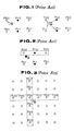
- Fig. 2 shows the basic principle of thin line preservation.
- reference symbols P 0.0 , P 0.1 , P 1.0 , P 1.1 , P 2.0 , and P 2.1 denote original pixels; and Q, a converted pixel.
- a thin line is determined using original pixel references shown in Fig. 3. More specifically, six original pixels in each of the horizontal and vertical directions (i.e., forming a cross shape) are referred to have an original pixel closest to a target of converted pixels as a central pixel.
- the present invention relates to binary image reduction adopted in a facsimile apparatus or the like and has as its object to provide a binary image reduction method which can reduce an image including an uneven pattern read from a scanner without being skipped or battered, and can reduce an image with high quality even if a reduction ratio is as small as, e.g., 1/4.
- a binary image reduction method wherein when horizontal and vertical conversion ratios ⁇ x and ⁇ y are respectively given by: 1/n x > ⁇ x ⁇ 1/(n x + 1) 1/n y > ⁇ y ⁇ 1/(n y + 1) (where n x and n y are natural numbers) some or all of 2(n x + 1) x 2(n y + 1) original pixels are referred in horizontal and vertical directions to have a converted pixel as a central pixel to detect a thin line whose horizontal line width in an original picture is equal to or smaller than n x pixels and whose vertical line width in the original picture is equal to or smaller than n y pixels, and which has a length equal to or larger than a predetermined value in horizontal, vertical, and oblique directions, and a value of the thin line is substituted in a converted pixel closest to the thin line upon detection of the thin line.
- the binary image reduction method of the present invention is as described above, and mainly includes four processing steps.
- a difference in characteristic feature between the reduction method of the present invention and a conventional reduction method is that, in the present invention, the length of a thin line is detected so as not to erroneously detect an uneven pattern as a thin line, and a means for referring to original pixels having a size described in step (2) is used to allow detection of the length of a thin line.
- a thin line can be prevented from being lost, and a converted picture free from degradation can be obtained.
- a thin line in a horizontal, vertical, or oblique direction can be prevented from being lost, and a satisfactorily converted picture can be obtained.
- the reduced character can be read, and a character smaller by 30% than the smallest character which can be reduced in a conventional method can be reduced.
- Fig. 5 is a function block diagram of an embodiment of the present invention.
- reference numeral 1 denotes an original picture reading means for reading out an original picture from a memory or the like; and 2, a converted pixel position calculating means for obtaining the positional relationship between converted pixels and original pixels when a converted picture is mapped to an original picture.
- the calculating means 2 determines the positional relationship between converted pixels and original pixels on the basis of a conversion ratio.
- Reference numeral 3 denotes an original pixel reference reading means for reading out values of 2(n x + 1) (horizontal direction) x 2(n y + 1) (vertical direction) original pixels to have a target of converted pixels as a central pixel; 4, a means for detecting a vertical/oblique thin line having a line width of n x pixels or less and a horizontal/oblique thin line having a line width of n y pixels or less from the values of the original pixel reference read out by the original pixel reference reading means 3, and for obtaining a converted pixel closest to the detected thin line; 5, a thin line length determination means for determining whether or not a thin line has a predetermined length; 6, a means for, when a target of converted pixels is a converted pixel closest to a thin line and the thin line has the predetermined length, substituting the value of the thin line in the converted pixel; 7, a means for, when no thin line is detected, or when the detected thin line has a length shorter than the predetermined length,
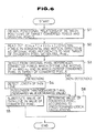
- Fig. 6 shows a flow of binary image reduction processing according to the present invention.
- values of converted pixels are sequentially determined in accordance with a predetermined rule, and the determination operation is repeated to form a converted picture.
- the embodiment shown in Fig. 5 and the binary image reduction method of the present invention will be described below with reference to the flow chart of Fig. 6.
- An original picture is read out by the original picture reading means 1, and a converted picture is mapped to the original picture by the converted pixel position calculating means 2, thus the position of a target of converted pixels on the original picture is obtained (S1 in Fig. 6).
- Fig. 7 exemplifies a case wherein the conversion ratio ⁇ satisfies 1/3 > ⁇ ⁇ 1/4.
- original pixels to be referred are enclosed in a dotted line 11.
- Each mark "o” indicates an original pixel
- a mark "x" indicates the position of a target of converted pixels.
- n 3
- the position of the target of converted pixels on an original picture is detected, and 2(n+1) (horizontal direction) x 2(n+1) (vertical direction) original pixels are sequentially read out from the contents of a line memory, having a capacity of 2(n+1) lines, for storing an original picture to have the target of converted pixel as a central pixel.
- the means 4 for detecting thin lines and calculating a value of a converted pixel detects detects connected pixels which are vertical/oblique connected pixels having a horizontal width of n x pixels or less, and/or are horizontal/oblique connected pixels having a vertical width of n y pixels or less, and the closest converted pixel of which is the target of converted pixels (S3 in Fig. 6).
- the thin line length determination means 5 determines whether or not the connected pixels have a predetermined length (S4 in Fig. 6).
- Figs. 8(a1) to 8(b4) show a detailed execution method of thin line detection of the present invention.
- Fig. 8(a1) shows an area which defines thin lines detection of a line width of one pixel
- Fig. 8(a2) shows an area which defines thin lines detection of a line width of two pixels.
- Fig. 8(b1) shows a thin line detection condition (to be referred to as a window hereinafter) for detecting a vertical line width of one pixel
- FIG. 8(b2) shows a window for detecting a vertical line width of two pixels
- Fig. 8(b3) shows a window for detecting a horizontal line width of one pixel
- Fig. 8(b4) shows a window for detecting a horizontal line width of two pixels.
- Thin lines are detected using the windows shown in Figs. 8(b1) to 8(b4) by sequentially detecting the presence/absence of thin lines in all the areas of an original pixel reference shown in Fig. 8(a1) or 8(a2).
- Figs. 8(a1) to 8(b4) show some examples of thin line detection.
- Windows used in thin line detection may have various formats depending on the line widths and lengths of thin lines and on a case of detection of only orthogonal thin lines or of detection of both orthogonal and oblique thin lines.
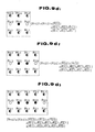
- 9(b1), 9(b2), and 9(b3) show windows for determining the presence of a thin line when a thin line having a line width of m pixels is present and the thin line of the m pixels has a length of two pixels or more in vertical, horizontal, and oblique directions;
- Figs. 9(c1), 9(c2), and 9(c3) show windows for determining the presence of a thin line when a thin line having a line width of m pixels is present and the thin line of the m pixels has a length of three pixels or more in vertical and horizontal directions; and Figs.
- 9(d1), 9(d2), and 9(d3) show windows for determining the presence of a thin line when a thin line having a line width of m pixels is present and the thin line of the m pixels has a length of three pixels or more in vertical, horizontal, and oblique directions.
- Figs. 8(b1) and 8(b3) exemplify a case of Fig. 9(c1)
- the windows shown in Figs. 8(b2) and 8(b4) exemplify a case of Fig. 9(c2).
- the entire area of an original pixel reference read out to have the target of converted pixels as the central pixel is checked to detect the presence/absence of a thin line corresponding to a window, and if a thin line is detected, it is checked if a converted pixel closest to the thin line is the target of converted pixels.
- the position of thin lines detection (to be referred to as a window position hereinafter) is determined in accordance with conditions of the conversion ratio, the length and width of the thin line, and the extending direction of the thin line (i.e., the vertical, horizontal, or oblique direction). Therefore, the presence/absence of a thin line can be detected from the window position determined as described above. Note that four different window positions are present according to positional relationship among the target of converted pixels and four original pixels surrounding the target of converted pixels.
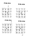
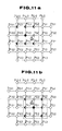
- Figs. 10(a) to 10(h) show window positions which are used for detecting orthogonal/oblique thin lines having a line width of one pixel and a line length of three pixels, i.e., window positions adopting the window shown in Fig. 9(d1) when the conversion ratio ⁇ satisfies 1/l > ⁇ ⁇ 1/2.
- a portion 21 surrounded by a dotted line corresponds to a window position.
- 10(a), 10(c), 10(e), and 10(g) show window positions for vertical/oblique thin lines having a line width of one pixel
- Figs. 10(b), 10(d), 10(f), and 10(h) show window positions for horizontal/oblique thin lines having a line width of one pixel.
- Figs. 10(a) to 10(h) exemplify four different cases, i.e., a case wherein the position of the target Q0 of converted pixels is close to the original pixel P 0.0 (Figs. 10(a) and 10(b)); a case wherein the position of the target Q0 is close to the original pixel P -1.0 (Figs. 10(c) and 10(d)); a case wherein the position of the target Q0 is close to the original pixel P 0.1 (Figs. 10(e) and 10(f)); and a case wherein the position of the target Q0 is close to the original pixel P -1.1 (Figs. 10(g) and 10(h)).
- the four different positions of the target Q0 of converted pixels correspond to 90°-rotated positions.
- the target Q0 of converted pixels may be present at a position separated an equal distance from two adjacent pixels of surrounding four original pixels, or it may be present at a position separated an equal distance from all the four surrounding original pixels. In these cases, the closest original pixel is determined in advance, so that the four different positions of the target of converted pixels can be obtained.
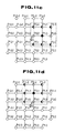
- Figs. 11(a) to 11(f) show window positions which are used for detecting orthogonal/oblique thin lines having line widths of one and two pixels and a line length of three pixels, i.e., window positions adopting the windows shown in Figs. 9(d1) and 9(d2) when the conversion ratio ⁇ satisfies 1/2 > ⁇ ⁇ 1/3.
- Figs. 11(a) to 11(f) exemplify only a case wherein the target Q0 of converted pixels is closest to the original pixel P 0.0 .
- the target Q0 takes four different positions like in Figs. 10(a) to 10(f).
- FIGS. 11(a) and 11(c) show window positions for vertical/oblique thin lines having a line width of one pixel;
- Figs. 11(b) and 11(d) show window positions for horizontal/oblique thin lines having a line width of one pixel;
- Fig. 11(e) shows a window position for vertical/oblique thin lines having a line width of two pixels;
- Fig. 11(f) shows a window position for horizontal/oblique thin lines having a line width of two pixels.
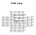
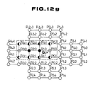
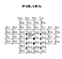
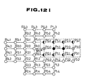
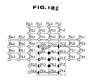
- Figs. 12(a) to 12(l) show window positions which are used for detecting orthogonal/oblique thin lines having line widths of one, two, and three pixels and a line length of three pixels, i.e., window positions adopting the windows shown in Figs. 9(d1), 9(d2), and 9(d3) when the conversion ratio ⁇ satisfies 1/3 > ⁇ ⁇ 1/4.
- Figs. 12(a) to 12(l) exemplify only a case wherein the target Q0 of converted pixels is closest to the original pixel P 0.0 in the same way as Figs. 11(a) to 11(f). Of course, the target Q0 takes four different positions as in Figs. 10(a) to 10(f).
- Figs. 12(a), 12(c), and 12(e) show window positions for vertical/oblique thin lines having a line width of one pixel
- Figs. 12(b), 12(d), and 12(f) show window positions for horizontal/oblique thin lines having a line width of one pixel
- Figs. 12(g) and 12(i) show window positions for vertical/oblique thin lines having a line width of two pixels
- Figs. 12(h) and 12(j) show window positions for horizontal/oblique thin lines having a line width of two pixels
- Fig. 12(k) shows a window position for vertical/oblique thin lines having a line width of three pixels
- Fig. 12(l) shows a window position for horizontal/oblique thin lines having a line width of three pixels.
- window positions shown in Figs. 10(a) to 12(l) are used for a case wherein the thin line has a length of three pixels.
- the window position for a thin line having a length of two pixels can be determined in the same manner as described above.
- the windows for thin lines having a length of two pixels adopt those shown in Figs. 9(a1), 9(a2), 9(a3), 9(b1), 9(b2), and 9(b3).
- the means 6 for substituting the value of the thin line in a converted pixel substitutes the value of the thin line in the value of the target of converted pixels (S5 in Fig. 6).
- the means 7 for calculating the value of the converted pixel shown in Fig. 5 calculates the value of the converted pixel (e.g., a value of the closest original pixel) in accordance with predetermined logical calculations, and substitutes the calculated value in the target of converted pixels.
- a method of detecting that the target of converted pixels is closer to a thin line than other converted pixels can be realized in such a manner that the central line of the detected thin line is calculated, distances from the central line to nearby converted pixels are compared to detect the closest converted pixel, and it is checked if the closest pixel is the target of converted pixels.
- a distance between original pixels is given by 1
- a distance between converted pixels is given by 1/ ⁇ if the conversion ratio is ⁇ .
- the center between two converted pixels is separated from both the converted pixels by 1/2 ⁇ .
- a converted picture may be formed by a method of reading out only original pixels necessary for thin line detection.
- the number of pixels necessary for thin line detection of the method (1) shown in Figs. 9(a1) to 9(b3) is smaller than that of the method (2) shown in Figs. 9(c1) to 9(d3).
- the number of hardware components can be smaller than that in the method (2); when it is realized in a software manner, the program size can be smaller than that in the method (2), resulting in a higher processing speed.
- the program size can be smaller than that in the method (2), resulting in a higher processing speed.
- image quality of a converted picture in the method (1) is inferior to that in the method (2).
- the number of pixels necessary for thin line detection in the method (2) is larger than that in the method (1).
- the number of hardware components is larger than that in the method (1); when it is realized in a software manner, the program size is larger and a processing speed is lower.
- the method (2) since thin lines having a length of three or more pixels are detected, even if an uneven pattern of one pixel is present in a thin line, the thin line will not be disconnected. For this reason, image quality of a converted image is superior to that in the method (1). Even if an uneven pattern of one pixel is present in a thin line, since the uneven pattern does not have a length of three or more pixels, the uneven pattern is never erroneously detected as a thin line.
- the above features can provide the following advantages. That is, when the number of hardware components is to be decreased or when a higher processing speed is to be attained, the method (1) is preferably employed. When an importance is put on image quality, the method (2) is preferable. In this manner, a desired method can be selected from the two methods.
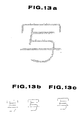
- Fig. 13(b) shows characters obtained by reducing an original picture shown in Fig. 13(a) by conventional reduction methods (the SPC method and the TP method), and Fig. 13(c) shows a character obtained by converting the original picture of Fig. 13(a) by the reduction method of the present invention.
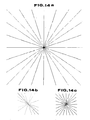
- Fig. 14(b) shows a pattern obtained by reducing an original picture having vertical, horizontal, and oblique lines shown in Fig. 14(a) by the conventional reduction method (the SPC method), and Fig. 14(c) shows a pattern obtained by converting the original picture of Fig. 14(a) by the reduction method of the present invention.
- binary image reduction free from loss of thin lines can be realized by the reduction method of the present invention.
Landscapes
- Engineering & Computer Science (AREA)
- Physics & Mathematics (AREA)
- General Physics & Mathematics (AREA)
- Theoretical Computer Science (AREA)
- Multimedia (AREA)
- Signal Processing (AREA)
- Image Processing (AREA)
- Editing Of Facsimile Originals (AREA)
Applications Claiming Priority (4)
| Application Number | Priority Date | Filing Date | Title |
|---|---|---|---|
| JP4153389 | 1989-02-23 | ||
| JP41533/89 | 1989-02-23 | ||
| JP119539/89 | 1989-05-12 | ||
| JP1-119539A JP3024975B2 (ja) | 1989-02-23 | 1989-05-12 | 縮小変換方法 |
Publications (3)
| Publication Number | Publication Date |
|---|---|
| EP0401058A2 true EP0401058A2 (de) | 1990-12-05 |
| EP0401058A3 EP0401058A3 (de) | 1992-10-28 |
| EP0401058B1 EP0401058B1 (de) | 1996-12-18 |
Family
ID=26381173
Family Applications (1)
| Application Number | Title | Priority Date | Filing Date |
|---|---|---|---|
| EP90400498A Expired - Lifetime EP0401058B1 (de) | 1989-02-23 | 1990-02-22 | Binäres Bildreduzierungsverfahren |
Country Status (5)
| Country | Link |
|---|---|
| US (1) | US5054099A (de) |
| EP (1) | EP0401058B1 (de) |
| KR (1) | KR940001049B1 (de) |
| CA (1) | CA2010637C (de) |
| DE (1) | DE69029429T2 (de) |
Cited By (2)
| Publication number | Priority date | Publication date | Assignee | Title |
|---|---|---|---|---|
| US5790714A (en) * | 1994-11-01 | 1998-08-04 | International Business Machines Corporation | System and method for scaling video |
| CN102375708A (zh) * | 2010-08-23 | 2012-03-14 | 三星电子株式会社 | 图像形成设备及其打印缩减图像的方法 |
Families Citing this family (15)
| Publication number | Priority date | Publication date | Assignee | Title |
|---|---|---|---|---|
| DE69033579T2 (de) * | 1989-04-10 | 2001-03-08 | Canon K.K., Tokio/Tokyo | Bildverkleinerungsgerät und Verfahren |
| US5457754A (en) * | 1990-08-02 | 1995-10-10 | University Of Cincinnati | Method for automatic contour extraction of a cardiac image |
| JP2562725B2 (ja) * | 1990-09-26 | 1996-12-11 | 大日本スクリーン製造株式会社 | 縮小画像生成装置 |
| EP0501814B1 (de) * | 1991-03-01 | 1998-12-16 | Canon Kabushiki Kaisha | Bildverarbeitungsgerät |
| JPH064655A (ja) * | 1992-06-22 | 1994-01-14 | Nippon Telegr & Teleph Corp <Ntt> | 高速画像縮小変換装置 |
| EP0644684B1 (de) * | 1993-09-17 | 2000-02-02 | Eastman Kodak Company | Digitaler integrierter Abtastratenumwandlungsschaltkreis und Anwendung bei einer schnellen Grössenänderung eines Bildes |
| JP3433983B2 (ja) * | 1993-09-20 | 2003-08-04 | 株式会社日立製作所 | 画像縮小装置および画像縮小方法 |
| JP3119150B2 (ja) * | 1995-02-02 | 2000-12-18 | 富士ゼロックス株式会社 | 画像処理装置および画像処理方法 |
| JP3427554B2 (ja) * | 1995-03-01 | 2003-07-22 | オムロン株式会社 | 画像処理装置及び方法 |
| JP3684029B2 (ja) * | 1997-05-12 | 2005-08-17 | 理想科学工業株式会社 | 画像太線化処理方法および装置 |
| JP2001060247A (ja) * | 1999-06-14 | 2001-03-06 | Fuji Xerox Co Ltd | 画像処理装置および画像処理方法 |
| TWI323606B (en) * | 2006-02-22 | 2010-04-11 | Huper Lab Co Ltd | Image noise reduction method based on local correlation |
| JP4963674B2 (ja) * | 2008-02-21 | 2012-06-27 | キヤノン株式会社 | 画像処理装置及び画像処理方法 |
| JP5316385B2 (ja) * | 2009-12-01 | 2013-10-16 | 富士ゼロックス株式会社 | 画像処理装置及び画像処理プログラム |
| JP6541320B2 (ja) * | 2014-09-24 | 2019-07-10 | キヤノン株式会社 | 画像処理装置、画像処理方法、コンピュータプログラム |
Family Cites Families (5)
| Publication number | Priority date | Publication date | Assignee | Title |
|---|---|---|---|---|
| JPS5739671A (en) * | 1980-08-20 | 1982-03-04 | Sanyo Electric Co Ltd | Shrinking system for facsimile picture signal |
| JPS5915359A (ja) * | 1982-07-16 | 1984-01-26 | Matsushita Graphic Commun Syst Inc | 画像縮小方法 |
| US4628534A (en) * | 1984-07-06 | 1986-12-09 | Honeywell Information Systems Inc. | Method for changing the resolution of compressed image data |
| JPS63184879A (ja) * | 1987-01-28 | 1988-07-30 | Toshiba Corp | 画像処理装置 |
| CA1306052C (en) * | 1988-03-18 | 1992-08-04 | Yoshiyuki Okada | Process and apparatus for reducing picture with fine line disappearance prevention |
-
1990
- 1990-02-21 US US07/482,660 patent/US5054099A/en not_active Expired - Lifetime
- 1990-02-22 EP EP90400498A patent/EP0401058B1/de not_active Expired - Lifetime
- 1990-02-22 CA CA002010637A patent/CA2010637C/en not_active Expired - Lifetime
- 1990-02-22 DE DE69029429T patent/DE69029429T2/de not_active Expired - Lifetime
- 1990-02-23 KR KR1019900002313A patent/KR940001049B1/ko not_active Expired - Lifetime
Cited By (5)
| Publication number | Priority date | Publication date | Assignee | Title |
|---|---|---|---|---|
| US5790714A (en) * | 1994-11-01 | 1998-08-04 | International Business Machines Corporation | System and method for scaling video |
| CN102375708A (zh) * | 2010-08-23 | 2012-03-14 | 三星电子株式会社 | 图像形成设备及其打印缩减图像的方法 |
| EP2424213A3 (de) * | 2010-08-23 | 2012-09-19 | Samsung Electronics Co., Ltd. | Bilderzeugungsvorrichtung und Verfahren zur Druckverkleinerung des Bildes dafür |
| US8928930B2 (en) | 2010-08-23 | 2015-01-06 | Samsung Electronics Co., Ltd. | Image forming apparatus and method of printing reduction image thereof |
| CN102375708B (zh) * | 2010-08-23 | 2016-04-06 | 三星电子株式会社 | 图像形成设备及其打印缩减图像的方法 |
Also Published As
| Publication number | Publication date |
|---|---|
| CA2010637C (en) | 1995-04-11 |
| DE69029429T2 (de) | 1997-07-24 |
| DE69029429D1 (de) | 1997-01-30 |
| KR940001049B1 (ko) | 1994-02-08 |
| EP0401058A3 (de) | 1992-10-28 |
| EP0401058B1 (de) | 1996-12-18 |
| JPH02290369A (ja) | 1990-11-30 |
| KR910016186A (ko) | 1991-09-30 |
| US5054099A (en) | 1991-10-01 |
| CA2010637A1 (en) | 1990-08-23 |
Similar Documents
| Publication | Publication Date | Title |
|---|---|---|
| EP0401058A2 (de) | Binäres Bildreduzierungsverfahren | |
| US5754710A (en) | Image resolution conversion method and appratus thereof | |
| US4533959A (en) | Picture processing apparatus | |
| US6587115B2 (en) | Method of an apparatus for distinguishing type of pixel | |
| US6469745B1 (en) | Image signal processor for detecting duplicate fields | |
| JP3399486B2 (ja) | カラー画像処理装置及び方法 | |
| CA1278373C (en) | Method of detecting boundary structures in a video signal | |
| US7116443B2 (en) | Neutral pixel detection using color space feature vectors wherein one color space coordinate represents lightness | |
| US5754708A (en) | Dotted image area detecting apparatus and dotted image area detecting method | |
| US5742348A (en) | Spatial frequency adaptive field--interpolation method and apparatus therefor | |
| JPH05328121A (ja) | 画像処理方法およびその装置 | |
| EP2315425B1 (de) | Verfahren zur kompression und expansion von bild-daten | |
| US20050008248A1 (en) | Method and filtering system for filtering edge directions | |
| US5491564A (en) | Data compression method and apparatus for binary image using Markov model encoding | |
| US5760921A (en) | Method of and apparatus for image processing | |
| US7139441B2 (en) | Image processing device performing inclination correcting processing | |
| US7145694B2 (en) | Image processing apparatus and method | |
| US5384647A (en) | Image processing apparatus comprising means for judging image area of pseudo half-tone image | |
| US5446802A (en) | Image processing apparatus comprising judgement means for judging dot photograph image, photograph image and character image | |
| JP2784278B2 (ja) | 画像変倍処理装置 | |
| JP3156691B2 (ja) | パターンマッチングを用いた符号化方法および符号化装置 | |
| JP3451490B2 (ja) | 画情報の処理方法 | |
| JP3024975B2 (ja) | 縮小変換方法 | |
| JP2877548B2 (ja) | 文書画像の属性判別方法 | |
| JP2525768B2 (ja) | 画像の縮小変換方法 |
Legal Events
| Date | Code | Title | Description |
|---|---|---|---|
| PUAI | Public reference made under article 153(3) epc to a published international application that has entered the european phase |
Free format text: ORIGINAL CODE: 0009012 |
|
| AK | Designated contracting states |
Kind code of ref document: A2 Designated state(s): DE FR GB |
|
| PUAL | Search report despatched |
Free format text: ORIGINAL CODE: 0009013 |
|
| AK | Designated contracting states |
Kind code of ref document: A3 Designated state(s): DE FR GB |
|
| 17P | Request for examination filed |
Effective date: 19921230 |
|
| 17Q | First examination report despatched |
Effective date: 19950602 |
|
| GRAG | Despatch of communication of intention to grant |
Free format text: ORIGINAL CODE: EPIDOS AGRA |
|
| GRAH | Despatch of communication of intention to grant a patent |
Free format text: ORIGINAL CODE: EPIDOS IGRA |
|
| GRAH | Despatch of communication of intention to grant a patent |
Free format text: ORIGINAL CODE: EPIDOS IGRA |
|
| GRAA | (expected) grant |
Free format text: ORIGINAL CODE: 0009210 |
|
| AK | Designated contracting states |
Kind code of ref document: B1 Designated state(s): DE FR GB |
|
| REF | Corresponds to: |
Ref document number: 69029429 Country of ref document: DE Date of ref document: 19970130 |
|
| ET | Fr: translation filed | ||
| PLBE | No opposition filed within time limit |
Free format text: ORIGINAL CODE: 0009261 |
|
| STAA | Information on the status of an ep patent application or granted ep patent |
Free format text: STATUS: NO OPPOSITION FILED WITHIN TIME LIMIT |
|
| 26N | No opposition filed | ||
| REG | Reference to a national code |
Ref country code: GB Ref legal event code: IF02 |
|
| PGFP | Annual fee paid to national office [announced via postgrant information from national office to epo] |
Ref country code: DE Payment date: 20090219 Year of fee payment: 20 |
|
| PGFP | Annual fee paid to national office [announced via postgrant information from national office to epo] |
Ref country code: GB Payment date: 20090217 Year of fee payment: 20 |
|
| PGFP | Annual fee paid to national office [announced via postgrant information from national office to epo] |
Ref country code: FR Payment date: 20090213 Year of fee payment: 20 |
|
| REG | Reference to a national code |
Ref country code: GB Ref legal event code: PE20 Expiry date: 20100221 |
|
| PG25 | Lapsed in a contracting state [announced via postgrant information from national office to epo] |
Ref country code: GB Free format text: LAPSE BECAUSE OF EXPIRATION OF PROTECTION Effective date: 20100221 |
|
| PG25 | Lapsed in a contracting state [announced via postgrant information from national office to epo] |
Ref country code: DE Free format text: LAPSE BECAUSE OF EXPIRATION OF PROTECTION Effective date: 20100222 |