EP0401376A1 - Systeme de diagnostic pour unite de commande numerique - Google Patents
Systeme de diagnostic pour unite de commande numerique Download PDFInfo
- Publication number
- EP0401376A1 EP0401376A1 EP89909438A EP89909438A EP0401376A1 EP 0401376 A1 EP0401376 A1 EP 0401376A1 EP 89909438 A EP89909438 A EP 89909438A EP 89909438 A EP89909438 A EP 89909438A EP 0401376 A1 EP0401376 A1 EP 0401376A1
- Authority
- EP
- European Patent Office
- Prior art keywords
- cnc
- processor
- diagnostic
- diagnosis
- processors
- Prior art date
- Legal status (The legal status is an assumption and is not a legal conclusion. Google has not performed a legal analysis and makes no representation as to the accuracy of the status listed.)
- Granted
Links
Images
Classifications
-
- G—PHYSICS
- G05—CONTROLLING; REGULATING
- G05B—CONTROL OR REGULATING SYSTEMS IN GENERAL; FUNCTIONAL ELEMENTS OF SUCH SYSTEMS; MONITORING OR TESTING ARRANGEMENTS FOR SUCH SYSTEMS OR ELEMENTS
- G05B19/00—Program-control systems
- G05B19/02—Program-control systems electric
- G05B19/18—Numerical control [NC], i.e. automatically operating machines, in particular machine tools, e.g. in a manufacturing environment, so as to execute positioning, movement or co-ordinated operations by means of program data in numerical form
- G05B19/406—Numerical control [NC], i.e. automatically operating machines, in particular machine tools, e.g. in a manufacturing environment, so as to execute positioning, movement or co-ordinated operations by means of program data in numerical form characterised by monitoring or safety
- G05B19/4063—Monitoring general control system
-
- G—PHYSICS
- G05—CONTROLLING; REGULATING
- G05B—CONTROL OR REGULATING SYSTEMS IN GENERAL; FUNCTIONAL ELEMENTS OF SUCH SYSTEMS; MONITORING OR TESTING ARRANGEMENTS FOR SUCH SYSTEMS OR ELEMENTS
- G05B2219/00—Program-control systems
- G05B2219/30—Nc systems
- G05B2219/33—Director till display
- G05B2219/33287—Program panel to program, enter data for diagnostic
-
- G—PHYSICS
- G05—CONTROLLING; REGULATING
- G05B—CONTROL OR REGULATING SYSTEMS IN GENERAL; FUNCTIONAL ELEMENTS OF SUCH SYSTEMS; MONITORING OR TESTING ARRANGEMENTS FOR SUCH SYSTEMS OR ELEMENTS
- G05B2219/00—Program-control systems
- G05B2219/30—Nc systems
- G05B2219/33—Director till display
- G05B2219/33288—Switch, select between normal and diagnostic control program
-
- G—PHYSICS
- G05—CONTROLLING; REGULATING
- G05B—CONTROL OR REGULATING SYSTEMS IN GENERAL; FUNCTIONAL ELEMENTS OF SUCH SYSTEMS; MONITORING OR TESTING ARRANGEMENTS FOR SUCH SYSTEMS OR ELEMENTS
- G05B2219/00—Program-control systems
- G05B2219/30—Nc systems
- G05B2219/33—Director till display
- G05B2219/33327—Self diagnostic of control system, servo system
Definitions
- the present invention relates to a diagnosis system for monitoring the interior state of a numerical control apparatus (CNC), and more specifically, to a CNC diagnosis system provided with a diagnostic processor.
- CNC numerical control apparatus
- Numerical control apparatuses and robot control apparatuses utilizes a multi-processor system including a plurality of processors, to enable simultaneous control of a multiplicity of axes.
- These control apparatuses comprise a plurality of the processors, many kinds of memories, a multiplicity of I/O interfaces, a position control circuit and the like, and if a malfunction occurs in any one of these elements, it is often difficult to detect exactly which element has malfunctioned.
- an object of the present invention is to provide a CNC diagnosis system utilizing a diagnostic processor.
- a diagnosis system of a numerical control apparatus for monitoring an internal state of the CNC, wherein a processor for the CNC acts as a host processor, and a diagnostic processor monitors the processor for the CNC or other processors in a usual CNC operation mode, and the diagnostic processor executes software for diagnosing the processor for the CNC and the other processors, as the host processor, to detect a malfunction in the CNC.
- CNC numerical control apparatus
- the CNC processor executes the software of the CNC, as the host processor, in a usual operating state, and the diagnostic processor monitors only the other processors.
- the CNC is switched to a diagnosis, mode and the diagnostic processor executes the diagnostic software, as the host processor, and diagnoses the other processors to thereby detect the cause of malfunction.
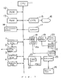
- FIG. 1 is a block diagram of a numerical control apparatus (CNC) as an embodiment of the present invention.
- CNC numerical control apparatus
- Figure 1 shows a hardware arrangement of a numerical control apparatus (CNC) as the embodiment of the present invention, wherein 1 designates a diagnostic processor which usually monitors other processors but executes diagnostic software in a diagnosis mode to detect the cause of a malfunction in the other processors.
- CNC numerical control apparatus
- Numeral 2 designates a communication port for connecting the diagnostic processor 1 with an external host computer through a communication line, and receiving instructions for a diagnosis from, or transmitting the result of a diagnosis to, the host computer.
- Numeral 3 designates a diagnostic ROM in which diagnostic software is stored; and 4 designates a diagnostic RAM which stores diagnostic software transmitted from the host computer, or temporarily stores diagnostic data to be transmitted to the host computer.
- Numeral 15 designates a display control circuit for converting a digital signal to a video signal; 16 designates a display unit, which is a CRT, a liquid crystal display unit or the like; and 17 designates a keyboard for inputting various data.
- Numeral 18 designates a position control circuit for controlling a servo motor; 19 designates a servo amplifier for controlling a speed of the servo motor; 20 designates the servo motor; 21 designates a tachometer generator for a speed feed back; and 22 designates a position detector and pulse coder, which comprises an optical scale or the like. Although as many as of these elements as the number of axes are installed, the elements only for one axis are shown here.
- the position control circuit 18 also contains an exclusive position control processor 18a, usually one CNC unit is provided with two to five of these processors. These position control processors 18a are also subjected to diagnosis to detect a malfunction thereof.
- Numeral 23 designates a programmable machine controller (PMC) for receiving instructions such as an M function, T function and the like, after converting same to signals, outputting them to thereby control a machine tool; 24 designates a processor for controlling the PMC 23; and 25 designates an I/O circuit connected to the machine tool 26 and receiving and transmitting digital signals from and to an external unit.
- PMC programmable machine controller
- the processor 11 controls the CNC as a whole, as a host processor for the overall CNC.
- the diagnostic processor 1 monitors only the processor 11, the position control processor 18a, and the processor 24 for the PMC, and when an abnormal state is detected, displays same at the display unit 16.
- the CNC When a malfunction of the CNC occurs and the cause thereof must be detected, the CNC is switched to a diagnosis mode and the diagnostic processor 1, as the host processor, executes the diagnostic software.
- the diagnostic software may be prestored in the diagnostic ROM 3, or transmitted from an external host computer and stored in the diagnostic RAM 4 as necessary.
- the diagnostic software When the CNC is not connected to the host computer, the diagnostic software must be stored in the diagnostic ROM 3. Further, when the CNC ic connected to the host computer, suitable diagnostic software can be transmitted to the diagnostic RAM 4 and executed in accordance with the cause of the malfunction. In this case, the result of a diagnosis can be transmitted to the host computer through the communication port 2, and processed thereby. For example, a service engineer working at the host computer can diagnose a malfunction without the necessity to actually go and inspect the overall CNC.
- the diagnostic processor 1 monitors only the processor 11, the position control processor 18a, and the processor 24 for the PMC, and when an abnormal state is detected, displays same at the display unit 16.
- the CNC When a malfunction of the CNC occurs and the cause thereof must be detected, the CNC is switched to a diagnosis mode and the diagnostic processor 1, as the host processor, executes the diagnostic software.
- the diagnostic software may be prestored in the diagnostic ROM 3, or transmitted from an external host computer and stored in the diagnostic RAM 4 as necessary.
- the diagnostic software When the CNC is not connected to the host computer, the diagnostic software must be stored in the diagnostic ROM 3. Further, when the CNC ic connected to the host computer, suitable diagnostic software can be transmitted to the diagnostic RAM 4 and executed in accordance with the cause of the malfunction. In this case, the result of a diagnosis can be transmitted to the host computer through the communication port 2, and processed thereby. For example, a service engineer working at the host computer can diagnose a malfunction without the necessity to actually go and inspect the CNC.
Landscapes
- Engineering & Computer Science (AREA)
- Human Computer Interaction (AREA)
- Manufacturing & Machinery (AREA)
- Physics & Mathematics (AREA)
- General Physics & Mathematics (AREA)
- Automation & Control Theory (AREA)
- Numerical Control (AREA)
- Testing And Monitoring For Control Systems (AREA)
- Test And Diagnosis Of Digital Computers (AREA)
Abstract
Applications Claiming Priority (3)
| Application Number | Priority Date | Filing Date | Title |
|---|---|---|---|
| JP63219864A JPH0268606A (ja) | 1988-09-02 | 1988-09-02 | Cncの診断方式 |
| JP219864/88 | 1988-09-02 | ||
| PCT/JP1989/000855 WO1990002981A1 (fr) | 1988-09-02 | 1989-08-22 | Systeme de diagnostic pour unite de commande numerique |
Publications (3)
| Publication Number | Publication Date |
|---|---|
| EP0401376A1 true EP0401376A1 (fr) | 1990-12-12 |
| EP0401376A4 EP0401376A4 (en) | 1993-12-15 |
| EP0401376B1 EP0401376B1 (fr) | 1996-03-13 |
Family
ID=16742253
Family Applications (1)
| Application Number | Title | Priority Date | Filing Date |
|---|---|---|---|
| EP89909438A Expired - Lifetime EP0401376B1 (fr) | 1988-09-02 | 1989-08-22 | Systeme de diagnostic pour unite de commande numerique |
Country Status (4)
| Country | Link |
|---|---|
| EP (1) | EP0401376B1 (fr) |
| JP (1) | JPH0268606A (fr) |
| DE (1) | DE68925965T2 (fr) |
| WO (1) | WO1990002981A1 (fr) |
Cited By (1)
| Publication number | Priority date | Publication date | Assignee | Title |
|---|---|---|---|---|
| EP0845721A4 (fr) * | 1996-06-17 | 2000-04-19 | Fanuc Ltd | Dispositif de commande numerique |
Families Citing this family (2)
| Publication number | Priority date | Publication date | Assignee | Title |
|---|---|---|---|---|
| JP2954615B2 (ja) * | 1989-11-24 | 1999-09-27 | 株式会社日立製作所 | モータ駆動制御装置 |
| JP3617196B2 (ja) * | 1996-07-02 | 2005-02-02 | 豊田工機株式会社 | 数値制御装置 |
Family Cites Families (8)
| Publication number | Priority date | Publication date | Assignee | Title |
|---|---|---|---|---|
| JPS55150012A (en) * | 1979-05-11 | 1980-11-21 | Hitachi Ltd | Test unit |
| JPS5717019A (en) * | 1980-07-07 | 1982-01-28 | Fanuc Ltd | Numerical controller |
| IL64077A (en) * | 1980-11-10 | 1984-12-31 | Kearney & Trecker Corp | Diagnostic communications system for computer controlled machine tools |
| JPS6159504A (ja) * | 1984-08-31 | 1986-03-27 | Amada Metoretsukusu:Kk | Nc装置 |
| JPS62224808A (ja) * | 1986-03-26 | 1987-10-02 | Mitsubishi Electric Corp | 数値制御装置 |
| JPS62243009A (ja) * | 1986-04-15 | 1987-10-23 | Fanuc Ltd | 診断用カセツトを有する数値制御装置 |
| JP2576935B2 (ja) * | 1993-02-24 | 1997-01-29 | シルバー株式会社 | 温風暖房機器の保護ガード装置 |
| JP3278696B2 (ja) * | 1993-05-26 | 2002-04-30 | 芝浦メカトロニクス株式会社 | 空缶回収機 |
-
1988
- 1988-09-02 JP JP63219864A patent/JPH0268606A/ja active Pending
-
1989
- 1989-08-22 DE DE68925965T patent/DE68925965T2/de not_active Expired - Fee Related
- 1989-08-22 EP EP89909438A patent/EP0401376B1/fr not_active Expired - Lifetime
- 1989-08-22 WO PCT/JP1989/000855 patent/WO1990002981A1/fr not_active Ceased
Cited By (1)
| Publication number | Priority date | Publication date | Assignee | Title |
|---|---|---|---|---|
| EP0845721A4 (fr) * | 1996-06-17 | 2000-04-19 | Fanuc Ltd | Dispositif de commande numerique |
Also Published As
| Publication number | Publication date |
|---|---|
| DE68925965D1 (de) | 1996-04-18 |
| WO1990002981A1 (fr) | 1990-03-22 |
| EP0401376A4 (en) | 1993-12-15 |
| JPH0268606A (ja) | 1990-03-08 |
| EP0401376B1 (fr) | 1996-03-13 |
| DE68925965T2 (de) | 1996-08-14 |
Similar Documents
| Publication | Publication Date | Title |
|---|---|---|
| US5274546A (en) | Diagnosis system of numerical control apparatus | |
| EP0962281B1 (fr) | Machine industrielle avec dispositif de détection d'une vibration irrégulière | |
| US5834916A (en) | Industrial robot and its control unit | |
| US5124622A (en) | Remote diagnosis system of numerical control apparatus | |
| EP0056060A1 (fr) | Système de traitement de données | |
| GB2246209A (en) | Workpiece manufacture | |
| KR100339865B1 (ko) | 감시제어장치 | |
| EP0383939B1 (fr) | Systeme de diagnostic de pannes | |
| US4965714A (en) | Apparatus for providing configurable safe-state outputs in a failure mode | |
| US5200678A (en) | Motor driving control apparatus | |
| EP0401376B1 (fr) | Systeme de diagnostic pour unite de commande numerique | |
| JPH0192081A (ja) | ロボット制御装置の運転履歴情報記憶、転送方式 | |
| JPH04211944A (ja) | 印刷機の電子制御装置の診断装置および方法 | |
| JPS62212705A (ja) | ロボツトの保守保全装置 | |
| JPH10297395A (ja) | 電子制御装置 | |
| JP2738029B2 (ja) | 制御装置 | |
| EP0919894B1 (fr) | Commande pour machine industrielle | |
| JP2003091302A (ja) | 工作機械の制御システムにおける異常検出装置 | |
| JPS61133412A (ja) | 故障診断装置 | |
| JP2767820B2 (ja) | 異常監視部の診断装置 | |
| JPS6299812A (ja) | 数値制御装置のモニタ方式 | |
| JPS5822469A (ja) | 中央監視制御装置 | |
| JP3494700B2 (ja) | 速度監視装置 | |
| SU1751721A1 (ru) | Способ технического диагностировани взаимосв занных элементов объекта и устройство дл его осуществлени | |
| JPH01209504A (ja) | マイクロプロセッサシステム |
Legal Events
| Date | Code | Title | Description |
|---|---|---|---|
| PUAI | Public reference made under article 153(3) epc to a published international application that has entered the european phase |
Free format text: ORIGINAL CODE: 0009012 |
|
| 17P | Request for examination filed |
Effective date: 19900522 |
|
| AK | Designated contracting states |
Kind code of ref document: A1 Designated state(s): DE FR GB |
|
| A4 | Supplementary search report drawn up and despatched |
Effective date: 19931022 |
|
| AK | Designated contracting states |
Kind code of ref document: A4 Designated state(s): DE FR GB |
|
| 17Q | First examination report despatched |
Effective date: 19940307 |
|
| GRAH | Despatch of communication of intention to grant a patent |
Free format text: ORIGINAL CODE: EPIDOS IGRA |
|
| GRAA | (expected) grant |
Free format text: ORIGINAL CODE: 0009210 |
|
| AK | Designated contracting states |
Kind code of ref document: B1 Designated state(s): DE FR GB |
|
| REF | Corresponds to: |
Ref document number: 68925965 Country of ref document: DE Date of ref document: 19960418 |
|
| ET | Fr: translation filed | ||
| PLBE | No opposition filed within time limit |
Free format text: ORIGINAL CODE: 0009261 |
|
| STAA | Information on the status of an ep patent application or granted ep patent |
Free format text: STATUS: NO OPPOSITION FILED WITHIN TIME LIMIT |
|
| 26N | No opposition filed | ||
| PGFP | Annual fee paid to national office [announced via postgrant information from national office to epo] |
Ref country code: FR Payment date: 19970811 Year of fee payment: 9 |
|
| PGFP | Annual fee paid to national office [announced via postgrant information from national office to epo] |
Ref country code: GB Payment date: 19970813 Year of fee payment: 9 |
|
| PGFP | Annual fee paid to national office [announced via postgrant information from national office to epo] |
Ref country code: DE Payment date: 19970901 Year of fee payment: 9 |
|
| PG25 | Lapsed in a contracting state [announced via postgrant information from national office to epo] |
Ref country code: GB Free format text: LAPSE BECAUSE OF NON-PAYMENT OF DUE FEES Effective date: 19980822 |
|
| GBPC | Gb: european patent ceased through non-payment of renewal fee |
Effective date: 19980822 |
|
| PG25 | Lapsed in a contracting state [announced via postgrant information from national office to epo] |
Ref country code: FR Free format text: LAPSE BECAUSE OF NON-PAYMENT OF DUE FEES Effective date: 19990430 |
|
| PG25 | Lapsed in a contracting state [announced via postgrant information from national office to epo] |
Ref country code: DE Free format text: LAPSE BECAUSE OF NON-PAYMENT OF DUE FEES Effective date: 19990601 |
|
| REG | Reference to a national code |
Ref country code: FR Ref legal event code: ST |