EP0401419A1 - Verrouillage automatique de volets roulants - Google Patents
Verrouillage automatique de volets roulants Download PDFInfo
- Publication number
- EP0401419A1 EP0401419A1 EP89110498A EP89110498A EP0401419A1 EP 0401419 A1 EP0401419 A1 EP 0401419A1 EP 89110498 A EP89110498 A EP 89110498A EP 89110498 A EP89110498 A EP 89110498A EP 0401419 A1 EP0401419 A1 EP 0401419A1
- Authority
- EP
- European Patent Office
- Prior art keywords
- roller shutter
- coupling
- lock according
- automatic roller
- tab
- Prior art date
- Legal status (The legal status is an assumption and is not a legal conclusion. Google has not performed a legal analysis and makes no representation as to the accuracy of the status listed.)
- Granted
Links
- 230000008878 coupling Effects 0.000 claims abstract description 31
- 238000010168 coupling process Methods 0.000 claims abstract description 31
- 238000005859 coupling reaction Methods 0.000 claims abstract description 31
- 210000000078 claw Anatomy 0.000 claims description 3
- 210000002414 leg Anatomy 0.000 description 15
- 230000000694 effects Effects 0.000 description 2
- 238000009434 installation Methods 0.000 description 2
- 238000006073 displacement reaction Methods 0.000 description 1
- 210000000689 upper leg Anatomy 0.000 description 1
Images
Classifications
-
- E—FIXED CONSTRUCTIONS
- E06—DOORS, WINDOWS, SHUTTERS, OR ROLLER BLINDS IN GENERAL; LADDERS
- E06B—FIXED OR MOVABLE CLOSURES FOR OPENINGS IN BUILDINGS, VEHICLES, FENCES OR LIKE ENCLOSURES IN GENERAL, e.g. DOORS, WINDOWS, BLINDS, GATES
- E06B9/00—Screening or protective devices for wall or similar openings, with or without operating or securing mechanisms; Closures of similar construction
- E06B9/56—Operating, guiding or securing devices or arrangements for roll-type closures; Spring drums; Tape drums; Counterweighting arrangements therefor
- E06B9/80—Safety measures against dropping or unauthorised opening; Braking or immobilising devices; Devices for limiting unrolling
- E06B9/82—Safety measures against dropping or unauthorised opening; Braking or immobilising devices; Devices for limiting unrolling automatic
- E06B9/86—Safety measures against dropping or unauthorised opening; Braking or immobilising devices; Devices for limiting unrolling automatic against unauthorised opening
-
- E—FIXED CONSTRUCTIONS
- E06—DOORS, WINDOWS, SHUTTERS, OR ROLLER BLINDS IN GENERAL; LADDERS
- E06B—FIXED OR MOVABLE CLOSURES FOR OPENINGS IN BUILDINGS, VEHICLES, FENCES OR LIKE ENCLOSURES IN GENERAL, e.g. DOORS, WINDOWS, BLINDS, GATES
- E06B9/00—Screening or protective devices for wall or similar openings, with or without operating or securing mechanisms; Closures of similar construction
- E06B9/02—Shutters, movable grilles, or other safety closing devices, e.g. against burglary
- E06B9/08—Roll-type closures
- E06B9/11—Roller shutters
- E06B9/15—Roller shutters with closing members formed of slats or the like
- E06B9/165—Roller shutters with closing members formed of slats or the like with slats disappearing in each other; with slats the distance between which can be altered
-
- E—FIXED CONSTRUCTIONS
- E06—DOORS, WINDOWS, SHUTTERS, OR ROLLER BLINDS IN GENERAL; LADDERS
- E06B—FIXED OR MOVABLE CLOSURES FOR OPENINGS IN BUILDINGS, VEHICLES, FENCES OR LIKE ENCLOSURES IN GENERAL, e.g. DOORS, WINDOWS, BLINDS, GATES
- E06B9/00—Screening or protective devices for wall or similar openings, with or without operating or securing mechanisms; Closures of similar construction
- E06B9/56—Operating, guiding or securing devices or arrangements for roll-type closures; Spring drums; Tape drums; Counterweighting arrangements therefor
- E06B9/80—Safety measures against dropping or unauthorised opening; Braking or immobilising devices; Devices for limiting unrolling
- E06B2009/801—Locking arrangements
- E06B2009/805—Locking arrangements located on or in the guides
Definitions
- the invention relates to an automatic roller shutter protection against pushing up the roller shutter curtain from profiled bars which are guided in U-shaped rails and are limitedly displaceable against each other in the direction of movement of the roller shutter curtain, with at least one locking member, the upper sharp end of which can be pressed against one leg of the guide rail and on the one hand via a first link-shaped coupling member for transmitting the pressing force is connected to a lower bracket fastened to a lower profile bar and via a second coupling member to an upper bracket fastened to an upper section bar, the locking member and the coupling links being movable perpendicular to the plane of the roller shutter curtain.
- the object of the invention is to provide a roller shutter safety device in which the locking member can be clamped and wedged directly within the guide rail without an articulated connection being arranged within this clamping path.
- the invention differs from the prior art in that the locking member is pressed like a gag with both ends on opposite legs of the U-rail.
- the locking element is pressed into the U-rail as a gag and wedged in it. So that can the entire clamping force can be absorbed within the locking member.
- the length of the locking member is fixed. There are no fluctuations or changes due to a joint connection.
- the coupling straps transmit the compressive forces that occur on the roller shutter curtain in the event of unauthorized manipulation and cause the gag-like locking element to be braced and wedged.
- An increased securing effect is achieved in that several pairs of locking members arranged in a cross shape are provided one above the other.
- a forced guidance of the locking members is ensured in that the locking members are connected to one another in the middle by a pivot pin.
- the centering within the U-rail is ensured in that the locking members are each coupled to the lower bracket or bracket bracket by a coupling bracket.
- a forced guidance of the locking members is ensured in that the two coupling straps are connected to the lower bracket or mounting bracket in a common hinge axis.
- the orderly actuation of the locking members is improved in that the locking members are articulated on coupling lugs which are connected to the upper bracket via a joint joint and the tension band.
- the engagement can be improved by connecting the upper coupling links to the joint via one or more mounting brackets.
- a firm connection with the roller shutter curtain is achieved in that the upper bracket is aligned two parallel to each other Has legs between which a wall of a profile bar is accommodated.
- the lower bracket which must be adjustable in height, receives a firm connection with the respective profile rod in that the lower bracket has claws on its leg.
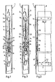
- the figures show a U-rail 1 with two legs 2 and 3.
- three profile bars 4 are shown, which are hung one inside the other with hook profiles or profile webs.
- a mutual displacement of the profiled bars is possible when the roller shutter is pulled up, compare FIG. 1.
- the profiled bars according to FIG. 3 essentially sit one after the other. This means that the mutual vertical spacing of the profile bars 4 is smaller in the closed state of the roller shutter.
- a bracket 6 is fastened to a lower profile bar, which is screwed, riveted or otherwise fixed to the lower profile bar 4 with a leg 7.
- On the leg claws 25 are angled, which penetrate into the wall of the profile bar and thus ensure a firm connection.
- the leg 7 can be adjusted in height to the respective installation conditions.
- the bracket 6 includes an articulated mounting bracket 8, at the upper end of which 9 coupling links 10 are articulated on a pin 9.
- the bracket tab 8 allows automatic adjustment and centering within the U-rail 1 regardless of the profile bars of the roller shutter curtain.
- Each coupling plate 10 is connected to a locking member 11 via a hinge pin.
- the two locking members are angular at the lower end 13.
- One or more locking teeth 14 are provided at the upper end.
- the two locking members 11 are crosswise coupled to one another via a hinge pin 15.
- a spreading spring 21 biases the coupling plates 10 in the locked position. You can couple several pairs of locking elements together.
- a coupling tab 16 is articulated.
- the two Koppella 16's are connected to a drawstring 18 via a joint 17. It is also possible to arrange a tab 24, which is drawn in dash-dotted lines in FIG. 2, between the joint 17 and the tension band 18.
- the tension band 18 can be a band, a wire, a chain, a link link pull or other tension element that can transmit a tensile force.
- the tension band 18 is fastened to an upper bracket 19, the legs 20a and 20b of which are connected to an upper profile bar 4.
- the legs 20a and 20b enclose the wall of the respective profile bar between them. Since the fastening elements such as screws or rivets hold in the thighs, a permanent and tear-resistant connection is guaranteed.
- two tabs 22 and 23 can also be provided, which are shown in dash-dotted lines in FIG. 2. These tabs can also transmit a compressive force and thus ensure that the roller shutter safety device is in direct contact.
- the roller shutter lock according to the invention is located within the U-rail 1 and lies against the central web thereof, as can be seen in particular from FIG. 2. Since all parts of the roller shutter safety device are plate-shaped, the roller shutter safety device has only a small extension in the longitudinal direction of the profile bars, so that it can be accommodated concealed within the U-rail without difficulty.
- Fig. 1 shows the roller shutter curtain in the pulled-apart state within the profile rail.
- the roller shutter lock is pulled apart because the brackets 6 and 19 are arranged accordingly on the profile bars, so that the individual members of the roller shutter lock elongate to each other.
- the movement of the roller shutter armor when lifting or lowering the same is not hindered by the roller shutter safety device in this state.
- each locking member 11 is gagged.
- the joint axis defined by the pin 9 and the axis of the joint 17 center themselves within the U-rail in such a way that the locking members 11 bear evenly on the legs 2, 3 of the U-rail 1 with both ends.
- the articulated connections favor a uniform spreading of the two locking members 11. This centering is favored by the mounting bracket 8 and the tension band 18, since this element moves in a transverse direction Allow direction of U-rail 1.
- each locking member 11 engages with at least one locking tooth 14 on the leg 3 of the U-rail 1.
- the lower end 13 is pressed against the opposite leg 2.
- the locking member 11 is wedged like a gag within the U-rail.
- the clamping force is transmitted by the locking member 11 itself to both legs of the U-rail. Since the locking member 11 is tab-shaped, a high clamping force can be achieved.
- the crosswise arrangement of two locking members 11 ensures an inevitable movement and wedging of the locking teeth 14 when the lower profile bars 4 are pushed up.
- a plurality of locking teeth ensure firm jamming in U-rails of different widths.
Landscapes
- Engineering & Computer Science (AREA)
- Structural Engineering (AREA)
- Architecture (AREA)
- Civil Engineering (AREA)
- Operating, Guiding And Securing Of Roll- Type Closing Members (AREA)
- Shutter-Related Mechanisms (AREA)
- Lock And Its Accessories (AREA)
Priority Applications (3)
| Application Number | Priority Date | Filing Date | Title |
|---|---|---|---|
| DE8989110498T DE58903182D1 (de) | 1989-06-09 | 1989-06-09 | Selbsttaetige rolladensicherung. |
| EP89110498A EP0401419B1 (fr) | 1989-06-09 | 1989-06-09 | Verrouillage automatique de volets roulants |
| AT89110498T ATE84112T1 (de) | 1989-06-09 | 1989-06-09 | Selbsttaetige rolladensicherung. |
Applications Claiming Priority (1)
| Application Number | Priority Date | Filing Date | Title |
|---|---|---|---|
| EP89110498A EP0401419B1 (fr) | 1989-06-09 | 1989-06-09 | Verrouillage automatique de volets roulants |
Publications (2)
| Publication Number | Publication Date |
|---|---|
| EP0401419A1 true EP0401419A1 (fr) | 1990-12-12 |
| EP0401419B1 EP0401419B1 (fr) | 1992-12-30 |
Family
ID=8201484
Family Applications (1)
| Application Number | Title | Priority Date | Filing Date |
|---|---|---|---|
| EP89110498A Expired - Lifetime EP0401419B1 (fr) | 1989-06-09 | 1989-06-09 | Verrouillage automatique de volets roulants |
Country Status (3)
| Country | Link |
|---|---|
| EP (1) | EP0401419B1 (fr) |
| AT (1) | ATE84112T1 (fr) |
| DE (1) | DE58903182D1 (fr) |
Cited By (2)
| Publication number | Priority date | Publication date | Assignee | Title |
|---|---|---|---|---|
| WO1998059145A3 (fr) * | 1997-06-20 | 1999-04-08 | Guido Langenbach | Porte roulante a mouvement rapide |
| EP2112321A1 (fr) | 2008-04-23 | 2009-10-28 | Zurfluh Feller | Volet roulant équipé d'un frein, frein et lame de freinage pour un tel volet |
Families Citing this family (1)
| Publication number | Priority date | Publication date | Assignee | Title |
|---|---|---|---|---|
| DE19528449C2 (de) * | 1995-08-03 | 2000-05-31 | Mecano Rapid Gmbh | Vorrichtung zum Sperren eines aus Lamellen bestehenden Rolladens gegen Hochschieben |
Citations (4)
| Publication number | Priority date | Publication date | Assignee | Title |
|---|---|---|---|---|
| DE2140237A1 (de) * | 1971-07-29 | 1973-02-15 | Walter Hardt | Rolladensicherung |
| DE2554667A1 (de) * | 1973-02-17 | 1977-06-08 | Walter Hardt | Vorrichtung zum schutz von sicherungen gegen unbefugtes hochdruecken eines rolladenpanzers |
| US4035008A (en) * | 1975-03-03 | 1977-07-12 | Walter Hardt | Automatic protection device for a roller blind against unauthorized raising |
| EP0058943A1 (fr) * | 1981-02-21 | 1982-09-01 | Hermann-Haus GmbH | Dispositif de sécurité anti-retour pour volets à rouleau |
-
1989
- 1989-06-09 DE DE8989110498T patent/DE58903182D1/de not_active Expired - Fee Related
- 1989-06-09 AT AT89110498T patent/ATE84112T1/de not_active IP Right Cessation
- 1989-06-09 EP EP89110498A patent/EP0401419B1/fr not_active Expired - Lifetime
Patent Citations (4)
| Publication number | Priority date | Publication date | Assignee | Title |
|---|---|---|---|---|
| DE2140237A1 (de) * | 1971-07-29 | 1973-02-15 | Walter Hardt | Rolladensicherung |
| DE2554667A1 (de) * | 1973-02-17 | 1977-06-08 | Walter Hardt | Vorrichtung zum schutz von sicherungen gegen unbefugtes hochdruecken eines rolladenpanzers |
| US4035008A (en) * | 1975-03-03 | 1977-07-12 | Walter Hardt | Automatic protection device for a roller blind against unauthorized raising |
| EP0058943A1 (fr) * | 1981-02-21 | 1982-09-01 | Hermann-Haus GmbH | Dispositif de sécurité anti-retour pour volets à rouleau |
Cited By (4)
| Publication number | Priority date | Publication date | Assignee | Title |
|---|---|---|---|---|
| WO1998059145A3 (fr) * | 1997-06-20 | 1999-04-08 | Guido Langenbach | Porte roulante a mouvement rapide |
| US6659158B2 (en) | 1997-06-20 | 2003-12-09 | Rite-Hite Holding Corporation | Quick-action rolling shutter door |
| US7111661B2 (en) | 1997-06-20 | 2006-09-26 | Rite-Hite Holding Corporation | Quick-action rolling shutter door |
| EP2112321A1 (fr) | 2008-04-23 | 2009-10-28 | Zurfluh Feller | Volet roulant équipé d'un frein, frein et lame de freinage pour un tel volet |
Also Published As
| Publication number | Publication date |
|---|---|
| ATE84112T1 (de) | 1993-01-15 |
| DE58903182D1 (de) | 1993-02-11 |
| EP0401419B1 (fr) | 1992-12-30 |
Similar Documents
| Publication | Publication Date | Title |
|---|---|---|
| EP0608485A1 (fr) | Support mural pour radiateur | |
| EP0324808A1 (fr) | Dispositif d'aiguillage electrique destine a etre fixe a un rail profile | |
| DE2613750A1 (de) | Lamellenjalousie mit senkrechten lamellen | |
| EP0401419B1 (fr) | Verrouillage automatique de volets roulants | |
| DE69504601T2 (de) | Vorrichtung zur Verstellung der Länge und/oder der Spannung eines elastischen Seils | |
| EP0885995B1 (fr) | Dispositif pour sécher le linge | |
| DE102019003532B3 (de) | Spannvorrichtung zum Spannen einer Schnur in einer Verschattungsanlage | |
| EP0724104A1 (fr) | Elément d'atténuation de contraintes et de fixation | |
| WO1996007811A1 (fr) | Echelle pouvant etre fixee de façon amovible a un batiment | |
| DE29718397U1 (de) | Torantriebseinrichtung und Befestigungsbausatz dafür | |
| DE3207105C2 (de) | Vorrichtung zum Befestigen der Innenseiten von Fahrschienen in Weichen und Kreuzungen im Bereich eines Radlenkers | |
| DE2643264B2 (de) | Haltevorrichtung für die Hobelkette an Kohlenhobeln | |
| DE1961080A1 (de) | Aufhaengevorrichtung fuer Gerueste,insbesondere Geruestboecke | |
| DE9403638U1 (de) | Rolladensicherung | |
| DE2000482B1 (de) | Vorrichtung zum Befestigen von Backenschienen in Weichen | |
| DE9107631U1 (de) | Wandhalterung für Radiatoren | |
| DE830565C (de) | Baugeruestklammer | |
| DE2238417A1 (de) | Befestigungseinrichtung fuer ein zugband eines lamellenvorhangs oder dergleichen | |
| DE3122424C2 (de) | Sicherungsbeschlag gegen unbefugtes Hochschieben eines Rolladens | |
| DE1073177B (de) | Klemmvorrichtung für die Verbindung des Förderseils mit einer im Schacht angeordneten Tragbühne | |
| LU102269B1 (de) | Raffstore und Verfahren zum Modifizieren eines Raffstores | |
| DE3149235C2 (de) | Kettfadenwächtereinrichtung | |
| DE2830753A1 (de) | Einrichtung an rollaeden zur sicherung gegen hochschieben | |
| DE2221132C3 (de) | Verstellbeschlag zur einstellbaren Befestigung der Frontplatte eines ausziehbaren Möbelteils | |
| DE9407706U1 (de) | Befestigungsvorrichtung für Vorhangschienen |
Legal Events
| Date | Code | Title | Description |
|---|---|---|---|
| PUAI | Public reference made under article 153(3) epc to a published international application that has entered the european phase |
Free format text: ORIGINAL CODE: 0009012 |
|
| AK | Designated contracting states |
Kind code of ref document: A1 Designated state(s): AT BE CH DE ES FR GB GR IT LI LU NL SE |
|
| RBV | Designated contracting states (corrected) |
Designated state(s): AT BE CH DE ES FR IT LI LU NL |
|
| 17P | Request for examination filed |
Effective date: 19901228 |
|
| 17Q | First examination report despatched |
Effective date: 19911223 |
|
| GRAA | (expected) grant |
Free format text: ORIGINAL CODE: 0009210 |
|
| AK | Designated contracting states |
Kind code of ref document: B1 Designated state(s): AT BE CH DE ES FR IT LI LU NL |
|
| PG25 | Lapsed in a contracting state [announced via postgrant information from national office to epo] |
Ref country code: ES Free format text: THE PATENT HAS BEEN ANNULLED BY A DECISION OF A NATIONAL AUTHORITY Effective date: 19921230 |
|
| REF | Corresponds to: |
Ref document number: 84112 Country of ref document: AT Date of ref document: 19930115 Kind code of ref document: T |
|
| REF | Corresponds to: |
Ref document number: 58903182 Country of ref document: DE Date of ref document: 19930211 |
|
| ITF | It: translation for a ep patent filed | ||
| ET | Fr: translation filed | ||
| EPTA | Lu: last paid annual fee | ||
| PLBE | No opposition filed within time limit |
Free format text: ORIGINAL CODE: 0009261 |
|
| STAA | Information on the status of an ep patent application or granted ep patent |
Free format text: STATUS: NO OPPOSITION FILED WITHIN TIME LIMIT |
|
| 26N | No opposition filed | ||
| PGFP | Annual fee paid to national office [announced via postgrant information from national office to epo] |
Ref country code: LU Payment date: 19980630 Year of fee payment: 10 |
|
| PGFP | Annual fee paid to national office [announced via postgrant information from national office to epo] |
Ref country code: NL Payment date: 19980730 Year of fee payment: 10 |
|
| PG25 | Lapsed in a contracting state [announced via postgrant information from national office to epo] |
Ref country code: LU Free format text: LAPSE BECAUSE OF NON-PAYMENT OF DUE FEES Effective date: 19990609 |
|
| PG25 | Lapsed in a contracting state [announced via postgrant information from national office to epo] |
Ref country code: NL Free format text: LAPSE BECAUSE OF NON-PAYMENT OF DUE FEES Effective date: 20000101 |
|
| NLV4 | Nl: lapsed or anulled due to non-payment of the annual fee |
Effective date: 20000101 |
|
| PGFP | Annual fee paid to national office [announced via postgrant information from national office to epo] |
Ref country code: BE Payment date: 20000623 Year of fee payment: 12 |
|
| PGFP | Annual fee paid to national office [announced via postgrant information from national office to epo] |
Ref country code: FR Payment date: 20000627 Year of fee payment: 12 |
|
| PGFP | Annual fee paid to national office [announced via postgrant information from national office to epo] |
Ref country code: AT Payment date: 20000628 Year of fee payment: 12 |
|
| PGFP | Annual fee paid to national office [announced via postgrant information from national office to epo] |
Ref country code: DE Payment date: 20000831 Year of fee payment: 12 |
|
| PGFP | Annual fee paid to national office [announced via postgrant information from national office to epo] |
Ref country code: CH Payment date: 20000905 Year of fee payment: 12 |
|
| PG25 | Lapsed in a contracting state [announced via postgrant information from national office to epo] |
Ref country code: AT Free format text: LAPSE BECAUSE OF NON-PAYMENT OF DUE FEES Effective date: 20010609 |
|
| PG25 | Lapsed in a contracting state [announced via postgrant information from national office to epo] |
Ref country code: LI Free format text: LAPSE BECAUSE OF NON-PAYMENT OF DUE FEES Effective date: 20010630 Ref country code: CH Free format text: LAPSE BECAUSE OF NON-PAYMENT OF DUE FEES Effective date: 20010630 Ref country code: BE Free format text: LAPSE BECAUSE OF NON-PAYMENT OF DUE FEES Effective date: 20010630 |
|
| BERE | Be: lapsed |
Owner name: GUST. ALBERTS G.M.B.H. & CO. K.G. Effective date: 20010630 |
|
| REG | Reference to a national code |
Ref country code: CH Ref legal event code: PL |
|
| PG25 | Lapsed in a contracting state [announced via postgrant information from national office to epo] |
Ref country code: FR Free format text: LAPSE BECAUSE OF NON-PAYMENT OF DUE FEES Effective date: 20020228 |
|
| PG25 | Lapsed in a contracting state [announced via postgrant information from national office to epo] |
Ref country code: DE Free format text: LAPSE BECAUSE OF NON-PAYMENT OF DUE FEES Effective date: 20020403 |
|
| PG25 | Lapsed in a contracting state [announced via postgrant information from national office to epo] |
Ref country code: IT Free format text: LAPSE BECAUSE OF NON-PAYMENT OF DUE FEES Effective date: 20050609 |