EP0401475A2 - Appareil pour reproduire un milieu d'enregistement - Google Patents
Appareil pour reproduire un milieu d'enregistement Download PDFInfo
- Publication number
- EP0401475A2 EP0401475A2 EP90104521A EP90104521A EP0401475A2 EP 0401475 A2 EP0401475 A2 EP 0401475A2 EP 90104521 A EP90104521 A EP 90104521A EP 90104521 A EP90104521 A EP 90104521A EP 0401475 A2 EP0401475 A2 EP 0401475A2
- Authority
- EP
- European Patent Office
- Prior art keywords
- open
- cover portion
- close body
- recording medium
- engagement
- Prior art date
- Legal status (The legal status is an assumption and is not a legal conclusion. Google has not performed a legal analysis and makes no representation as to the accuracy of the status listed.)
- Granted
Links
- 238000003780 insertion Methods 0.000 claims abstract description 22
- 230000037431 insertion Effects 0.000 claims abstract description 22
- 238000005286 illumination Methods 0.000 description 3
- 238000000034 method Methods 0.000 description 2
- 229910000831 Steel Inorganic materials 0.000 description 1
- 230000001154 acute effect Effects 0.000 description 1
- 230000003796 beauty Effects 0.000 description 1
- 230000005540 biological transmission Effects 0.000 description 1
- 229940090961 chromium dioxide Drugs 0.000 description 1
- IAQWMWUKBQPOIY-UHFFFAOYSA-N chromium(4+);oxygen(2-) Chemical compound [O-2].[O-2].[Cr+4] IAQWMWUKBQPOIY-UHFFFAOYSA-N 0.000 description 1
- AYTAKQFHWFYBMA-UHFFFAOYSA-N chromium(IV) oxide Inorganic materials O=[Cr]=O AYTAKQFHWFYBMA-UHFFFAOYSA-N 0.000 description 1
- 238000001514 detection method Methods 0.000 description 1
- 238000010586 diagram Methods 0.000 description 1
- 230000002452 interceptive effect Effects 0.000 description 1
- 229910052751 metal Inorganic materials 0.000 description 1
- 239000002184 metal Substances 0.000 description 1
- 239000011347 resin Substances 0.000 description 1
- 229920005989 resin Polymers 0.000 description 1
- 239000010959 steel Substances 0.000 description 1
Images


Classifications
-
- G—PHYSICS
- G11—INFORMATION STORAGE
- G11B—INFORMATION STORAGE BASED ON RELATIVE MOVEMENT BETWEEN RECORD CARRIER AND TRANSDUCER
- G11B33/00—Constructional parts, details or accessories not provided for in the other groups of this subclass
- G11B33/12—Disposition of constructional parts in the apparatus, e.g. of power supply, of modules
- G11B33/121—Disposition of constructional parts in the apparatus, e.g. of power supply, of modules the apparatus comprising a single recording/reproducing device
- G11B33/123—Mounting arrangements of constructional parts onto a chassis
-
- G—PHYSICS
- G11—INFORMATION STORAGE
- G11B—INFORMATION STORAGE BASED ON RELATIVE MOVEMENT BETWEEN RECORD CARRIER AND TRANSDUCER
- G11B15/00—Driving, starting or stopping record carriers of filamentary or web form; Driving both such record carriers and heads; Guiding such record carriers or containers therefor; Control thereof; Control of operating function
- G11B15/02—Control of operating function, e.g. switching from recording to reproducing
- G11B15/10—Manually-operated control; Solenoid-operated control
-
- G—PHYSICS
- G11—INFORMATION STORAGE
- G11B—INFORMATION STORAGE BASED ON RELATIVE MOVEMENT BETWEEN RECORD CARRIER AND TRANSDUCER
- G11B15/00—Driving, starting or stopping record carriers of filamentary or web form; Driving both such record carriers and heads; Guiding such record carriers or containers therefor; Control thereof; Control of operating function
- G11B15/675—Guiding containers, e.g. loading, ejecting cassettes
-
- G—PHYSICS
- G11—INFORMATION STORAGE
- G11B—INFORMATION STORAGE BASED ON RELATIVE MOVEMENT BETWEEN RECORD CARRIER AND TRANSDUCER
- G11B31/00—Arrangements for the associated working of recording or reproducing apparatus with related apparatus
-
- G—PHYSICS
- G11—INFORMATION STORAGE
- G11B—INFORMATION STORAGE BASED ON RELATIVE MOVEMENT BETWEEN RECORD CARRIER AND TRANSDUCER
- G11B33/00—Constructional parts, details or accessories not provided for in the other groups of this subclass
- G11B33/02—Cabinets; Cases; Stands; Disposition of apparatus therein or thereon
- G11B33/027—Covers
Definitions
- the present invention relates to a recording medium player apparatus such as a cassette tape recorder, and particularly to a recording medium player apparatus such as a small-sized cassette tape recorder having a recording medium insertion slot.
- the area available as an operation face of the recording medium player apparatus is extremely limited.
- a suitable apparatus mounting location where the driver of the vehicle can very easily perform operation of the apparatus is only an extremely limited space, such as a portion of the vehicle dashboard or console. Accordingly, it is required to additionally provide a circuit for operational control of a radio tuning function and for indication thereof within such a limited area of 18 cm x 5cm as described above.
- a dustproof door for covering a cassette tape insertion slot is also used as a dial portion of a radio receiver, for example, as disclosed in Japanese Utility Model Publication No. 43-29326.
- wasted space is used effectively where the radio receiver, built-in type car stereo apparatus is only used as a radio receiver.
- the car-stereo apparatus is used as a recording medium player apparatus, such as a tape recorder, the space cannot be used for disposing circuit elements for display and control because the dustproof door is pushed into the inside of the body when a cassette tape is inserted.
- Fundamental control comprises the tape recorder, including control on PLAY (reproduction), FF (fast feed), REW (rewind), STOP (stoppage), and EJECT (take-out a tape cassette), on/off of power switch, sound volume, sound quality, etc.
- PLAY production
- FF fast feed
- REW rewind
- STOP stoppage
- EJECT take-out a tape cassette
- the difficulty is particularly acute in the case where a radio-tuning function, etc., is integrally provided in addition to a tape recorder function such as an audio appliance or in the case where a video function such as a television set, a VTR (video tape recorder), or the like, is provided in addition to such an audio function.
- a radio-tuning function etc.
- a video function such as a television set, a VTR (video tape recorder), or the like
- an indicator for indicating operational information with respect to operations of a playing portion, a tuner, etc., and play information with respect to contents of play, and so on does not have a relatively large area, then an operator cannot distinguish or recognize the contents of information indicated. It is, however, difficult to increase the area of the indicator when a recording medium insertion slot is provided in the front surface of the player apparatus as described above, so that there is a disadvantage in that the indicator cannot achieve its indicating functions sufficiently.
- a hinge mechanism 106 is provided for pivotally attaching the open/close body 104 onto the housing in the vicinity of the front surface of the open/close body 104. In such a configuration, however, the hinge mechanism 106 is always exposed so as to detract from the overall appearance of the recording medium player apparatus.
- the recording medium player apparatus comprises an open/close body provided so as to cover or not cover a recording medium insertion slot formed in a front surface portion of a housing and provided with an operation portion for controlling the operation of a play means.
- the apparatus further comprises a support member pivotally provided on the housing for pivotally supporting at a free end portion thereof the open/close body, a first driving means for pivotally moving the support member, and a second driving means for pivotally moving the open/close body relative to the support member.
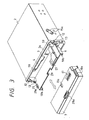
- the cassette deck has a housing including a cabinet portion 2 as a main part which is removably inserted and loaded into a holding space through an insertion slot of a holding box fixed on a dashboard (not shown) of a car. Further, a front surface portion of the cabinet portion 2, that is, a front panel portion 3 is exposed outside of the holding space.
- the cassette deck is provided with an open/close body 5 for openably covering a cassette tape insertion slot 4 (see Figure 2) formed in the front panel portion 3 for insertion of a cassette tape (not shown) acting as a recording medium.
- the open/close body 5 is constituted by an inner cover portion 6 and an outer cover portion 7.
- the inner cover portion 6 is made of a steel plate or the like and is generally formed like a rectangular plate so that the inner cover portion 6 can cover substantially the whole surface of the front panel portion 3 including the cassette tape insertion slot 4.
- the outer cover portion 7 is constituted by a hollow rectangular-parallelepiped housing made of resin or the like and is removably attached to the inner cover portion 6. More specifically, a slot 10a is formed in each of the longitudinally opposite ends of the outer cover portion 7 so that a U-shaped channel end portion 10b formed at each of the longitudinally opposite ends of the inner cover portion 6 slidably engages with the corresponding slot 10a. Further, an engagement recess portion 11a having a tip head portion is formed in the rear surface of the outer cover portion 7 and an engagement projecting portion 11b having a tip head portion is formed on the front surface portion of the inner cover portion 6 (see Figure 4) so that the engagement projection portion 11b can be fitted into the engagement recess portion 11a.
- the inner cover portion 6 is pivotally supported by a pair of support members 12 at the left and right side portions of and at one transverse edge portion (e.g., the lower edge portion) of the inner cover portion 6.
- the support members 12 are pivotally attached through pins 12a on inner surfaces of left and right opposite side wall portions of the housing 2 so as to pivotally support the inner cover portion 6 by the free end portions thereof respectively.
- the pivotal movement of each of the inner cover portion 6 and the support members 12 is performed within a plane perpendicular to the main surface of the front panel portion 3 of the housing 2.
- cylindrical bosses 12b are pivotally provided at the respective free ends of the support members 12 so that pins 6a projectingly provided at side end portions of the inner cover portion 6 are fitted into the bosses 12b.
- the pins 6a are in a fixed state relative to the inner cover portion 6.
- the pins 6a are longer than the bosses 12b so tht the pins 6a project from the bosses 12b, and the first gear members, that is, fan-like gears 13 are fixed to the projected portions of the pins 6a, respectively.
- the fan-like gears 13 are arranged so that the rotary central axes thereof coincide with the center axis of the pivotal movement of the inner cover portion 6.
- the fan-like gears 13 are provided so as to be rotatable relative to the support members 12 while being fixed relative to the inner cover portion 6.
- Second gear members that is, gears 14 are provided on the support members 12 at the free end portions thereof so as to mesh with the fan-like gears 13, respectively.
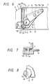
- the gears 14 mesh with third gear members, that is, other fan-like gears 15 fixed to the cabinet portion 2, through a pair of pins 15a, respectively (see Figures 5 and 6).
- spring members 17 are provided for urging the inner cover portion 6 to its open position.
- the support members 12 are pivoted clockwise from the position illustrated in Figure 6 by the urging force of the respective spring members 17 so that the open/close body 5 constituted by the inner cover portion 6 and the outer cover portion 7 is pivoted to its open position.
- the support members 12 are returned to the position shown in Figure 6 against the urging force of the respective spring members 17 so that the open/close body 5 is returned to the closed position as shown in Figure 6.
- the above-mentioned spring members 17 constitute a first driving means for pivoting the support members 12.
- This first driving means, the fan-like gears 13 and 15, and the gears 14 constitute a second driving means for pivoting the open/close body 5 relative to the support members 12 in synchronism with the pivotal movement of the support members 12. That is, the first driving means is utilized as part of the second driving means.
- an engagement/stopper member 21 having a pin 21a is fixedly provided on the left rear surface of the inner cover portion 6.
- an engagement/stopper lever 23 is swingably attached through a support pin 23b onto a fixed chassis 22 provided inside the cabinet portion 2 so that the engagement/stopper lever 23 can engage with the pin 21a of the engagement/stopper member 21 by means of a pawl portion 23a provided at a free end of the engagement/stopper lever 23.
- a solenoid plunger 25 is provided under the engagement/stopper lever 23 so that a rod 25a of the solenoid plunger 25 is connected to the engagement/stopper lever 23 through a connection pin 25b.
- the solenoid plunger 25 attracts the rod 25a so that the engagement/stopper lever 23 swings to the position as shown by solid lines in Figure 9 to engage with the engagement/stopper member 21, and when the power supply to the solenoid plunger 25 is cut off the engagement/stopper lever 23 is swung to the position as shown by two-dotted chain lines in Figure 9 by the urging force of a coil spring 26 to thereby be released from the state of engagement with the engagement/stopper member 21.
- the inner cover portion 6 is put into the open state by the biasing force of the spring members 17.
- the engagement/stopper member 21, the engagement/stopper lever 23, and the solenoid plunger 25 constitute an inner cover portion engagement/stopper means, that is, a first engagement/stopper means for locking the inner cover portion 6 to the cabinet portion 2.
- a first engagement/stopper means for locking the inner cover portion 6 to the cabinet portion 2.
- an engagement/stopper plate 28 having a plate spring fixed thereto in a cantilever relation is secured to a rear surface portion of the outer cover portion 7 and an engagement/stopper protrusion 28a is attached to a free end portion of the engagement/stopper plate 28.
- a pawl-like opening 29 is formed in the inner cover portion 6 so that the engagement/stopper protrusion 28a can engage with the opening 29.
- the engagement/stopper plate 28 and the opening 29 constitute a second engagement/stopper means for locking the outer cover portion 7 to the cabinet portion 2, that is, for locking the outer cover portion 7 to the inner cover portion 6 which is fixed to the cabinet portion 2 by the above-mentioned first engagement/stopper means.
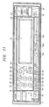
- an operation portion including various operation switches for controlling operation of a cassette tape player and so on provided in the cabinet portion 2, and an indicator portion 31 are provided on the front surface portion of the outer cover portion 7. Further, an indicator driving circuit for driving the indicator portion is provided inside the outer cover portion 7.
- electronic sound volume control switches 32 and 33 are provided in the operation portion on the outer cover portion 7.
- the switches 32 and 33 function to make the sound volume louder or softer while they are pushed down, respectively.
- control switches 35-40 which are used for music jump-selecting operation are provided so as to produce commands for indicating the number of pieces of music to be jumped to a target one ahead (or behind) of a current one.
- a fast-feed switch 42, a rewinding switch 43, and a switch 45 for changing over the tape running direction in auto-reverse operation are provided on the side of the control switches 35-40.
- a door open switch 47 is provided for opening the above-mentioned open/close body 5 and a source change-over switch 48 disposed under the door open switch 47 is provided for selecting which one of the cassette deck, the tuner, and the digital audio disc player, of the operation portion is to be used.
- a sensor 49 is provided under the source change-over switch 48 for receiving a signal from a remote controller for remote controlling the operation portion.
- An automatic sound levelizing switch 51 is such that, if this switch is pushed, the sound volume is automatically made softer during the time of car stoppage, while the sound volume is made louder during the time of car running when noises become loud.
- a shift switch 52 is provided under the sound volume control switches 32 and 33, and a loudness switch 53, a clock switch 54, an illumination change-over switch 55, etc., are arranged in order on the side of the shift switch 52.
- the illumination change-over switch is pushed, the illumination color of the indicator portion 31 is changed into, for example, green and red.
- change-over switches 56a-56c for selecting which one of the functions of the cassette deck, the tuner, and the digital audio disc player, the indicator portion 31 should perform indication.
- the indicator portion 31 provided on the outer cover portion 7 together with the above-mentioned operation portion indication is made with respect to the tape play time, the operation mode, the distinction of current playing side between the sides A and B, and so on, in use of the cassette deck. Indication is made with respect to the program selection information, the operation mode, etc. during use of the tuner, while indication is made with respect to the disc play elapsed time, the operation mode, etc. during use of the digital audio disc player. Further, as described above, an indicator driving circuit for driving the indicator portion 31 is provided inside the outer cover portion 7.
- an eject switch 57 for ejecting a cassette tape is disposed outside the cassette deck on the rear surface of the inner cover portion 6. Further, door closure detection switches 59 are provided on the front panel portion 3 so that the switches 59 detect the open/close of the inner cover portion 6 through engagement with the inner cover portion 6.
- the transmission/reception of signals between the operation portion provided on the outer cover portion 7 and the CPU (control circuit) provided in the cabinet portion 2 is performed through connection between the terminal groups 61 and 62 correspondingly provided on the rear surface portion of the outer cover portion 7 and the front surface portion of the inner cover portion 6, respectively (see Figures 3 and 4).
- the terminal groups 61 and 62 power is supplied to the outer cover portion 7 from the cabinet portion 2 side.
- the terminal groups 61 and 62 are connected to each other by mounting the outer cover portion 7 onto the inner cover portion 6 and disconnected from each other by removing the outer cover portion 7 from the inner cover portion 6.
- the indicator driving circuit for driving the indicator portion 31 on the outer cover portion 7 is not provided on the cabinet portion 2 side but provided in the outer cover portion 7, the terminal groups of 61 and 62 are reduced in number.
- the CPU 72 When the door open switch 47 is pushed, the CPU 72 first cuts off the supply of power to the solenoid plunger 25 so as to release the locked state between the engagement/stopper member 21 and the engagement/stopper lever 23 to thereby enable the inner cover portion 6 to swing. Then, the open/close body 5 constituted by the inner cover portion 6 and outer cover portion 7 is pivotally moved by the urging force of the spring members 17 toward the open position shown in Figures 2 and 13.
- the open/close body 5 reaches the open position shown in Figure 2.
- the eject switch 57 on the rear surface of the inner cover portion 6 can be pushed so that the cassette tape (not shown) is ejected outside through the cassette tape insertion slot 4 of the front panel portion 3 so as to be withdrawn by the operator.
- the operator parks the car in which the cassette deck is mounted so as to leave the car, the operator pushes down the engagement/stopper protrusion 28a of the outer cover portion 7 so that the engagement/stopper plate 28 of the outer cover portion 7 is bent so as to release the locked state of the outer cover portion 7 to the inner cover portion 6 as shown in Figure 10(b).
- the operator can draw out the outer cover portion 7 from the inner cover portion 6 to carry the outer cover portion 7 with him or her.
- the open/close body 5 is divided into the inner cover portion 6 which is pivotal to the front panel portion 3 so as to open/close the cassette tape insertion slot 4, and the outer cover portion 7 which is arranged so as to be removably mounted on the inner cover portion 6 and includes the operation portion for controlling the operation of the play means provided within the cabinet portion 2.
- the present invention is not limited to such a configuration but is applicable to a modified configuration in which the outer cover portion 7 is pivotally attached to the front panel portion 3 with the inner cover portion 6 omitted.
- the recording medium player apparatus comprises an open/close body which is provided so as to openably/closably cover a recording medium insertion slot formed in the front surface portion of a housing and which is provided with an operation portion for controlling the operation of a play means, and further comprises a support member for pivotally supporting at its free end the open/close body, a first driving means for pivotally moving the support member, and a second driving means for pivotally moving the open/close body relative to the support member.
- the apparatus is configured so that the open/close body is largely separated from the edge portion of the front panel portion of the housing when the open/close body is in the open position where the open/close body opens the recording medium insertion slot.
- the pivotal portion of the open/close body can be disposed in the vicinity of the rear surface portion of the open/close body, whereby when the open/close body is in the closed position where the open/close body closes the recording medium insertion slot the above-mentioned pivotal portion is covered by the front panel portion so as not to be visible to thereby obtain a sense of beauty in appearance.
Landscapes
- Engineering & Computer Science (AREA)
- Multimedia (AREA)
- Casings For Electric Apparatus (AREA)
- Feeding And Guiding Record Carriers (AREA)
Applications Claiming Priority (2)
| Application Number | Priority Date | Filing Date | Title |
|---|---|---|---|
| JP1144413A JPH081721B2 (ja) | 1989-06-07 | 1989-06-07 | 記録媒体演奏装置 |
| JP144413/89 | 1989-06-07 |
Publications (3)
| Publication Number | Publication Date |
|---|---|
| EP0401475A2 true EP0401475A2 (fr) | 1990-12-12 |
| EP0401475A3 EP0401475A3 (fr) | 1991-02-27 |
| EP0401475B1 EP0401475B1 (fr) | 1995-05-31 |
Family
ID=15361595
Family Applications (1)
| Application Number | Title | Priority Date | Filing Date |
|---|---|---|---|
| EP90104521A Expired - Lifetime EP0401475B1 (fr) | 1989-06-07 | 1990-03-09 | Appareil pour reproduire un milieu d'enregistement |
Country Status (4)
| Country | Link |
|---|---|
| US (1) | US5010437A (fr) |
| EP (1) | EP0401475B1 (fr) |
| JP (1) | JPH081721B2 (fr) |
| DE (1) | DE69019780T2 (fr) |
Cited By (9)
| Publication number | Priority date | Publication date | Assignee | Title |
|---|---|---|---|---|
| EP0639834A3 (fr) * | 1993-08-17 | 1995-07-19 | Matsushita Electric Industrial Co Ltd | Appareil récepteur de télévision avec unité de magnétoscope incorporée. |
| US5539463A (en) * | 1993-08-24 | 1996-07-23 | Sony Corporation | Cassette eject mechanism, battery loading mechanism and mechanical chassis supporting mechanism |
| GB2308719A (en) * | 1995-12-29 | 1997-07-02 | Sony Corp | Electronic apparatus with a pivoting, removable control panel |
| GB2312778A (en) * | 1996-04-30 | 1997-11-05 | Daewoo Electronics Co Ltd | Detachable pivoting control panel for car audio |
| GB2314448A (en) * | 1996-06-21 | 1997-12-24 | Daewoo Electronics Co Ltd | Detachable sliding control panel for car audio |
| WO2000024000A1 (fr) * | 1998-10-17 | 2000-04-27 | Daewoo Electronics Co., Ltd. | Partie bouton d'ejection d'un systeme audio pour voiture comprenant un panneau de commande amovible |
| EP0938093A3 (fr) * | 1998-02-24 | 2001-06-13 | Aiwa Co., Ltd. | Assemblage d'entraínement de bande coulissant |
| EP1067554A3 (fr) * | 1999-07-02 | 2001-10-10 | Pioneer Corporation | Appareil de reproduction de support d'enregistrement |
| FR2855305A1 (fr) * | 2003-05-22 | 2004-11-26 | Renault Sa | Lecteur de disques comportant un moyen de guidage pour l'introduction d'un disque |
Families Citing this family (21)
| Publication number | Priority date | Publication date | Assignee | Title |
|---|---|---|---|---|
| JPH07105130B2 (ja) * | 1989-08-31 | 1995-11-13 | パイオニア株式会社 | 記録媒体演奏装置 |
| JP2547924Y2 (ja) * | 1991-05-16 | 1997-09-17 | パイオニア株式会社 | カーステレオ装置 |
| TW232732B (fr) * | 1991-10-02 | 1994-10-21 | Philips Gloeilamdenfabrieken Nv | |
| JP2665130B2 (ja) * | 1992-08-10 | 1997-10-22 | 三星電子株式会社 | ディスクプレイヤメカニズム |
| US5739970A (en) * | 1994-09-20 | 1998-04-14 | Fujitsu Limited | Magnetic tape unit |
| KR970038807A (ko) * | 1995-12-28 | 1997-07-24 | 배순훈 | 전면 패널 회동구조 |
| DE19908067B4 (de) * | 1999-02-25 | 2004-11-11 | Harman Becker Automotive Systems (Becker Division) Gmbh | Autoradio mit abnehmbarem Bedienteil |
| DE10066145B4 (de) * | 2000-04-14 | 2009-01-29 | Kraussmaffei Technologies Gmbh | Verfahren zum Betrieb einer Spritzgießmaschine mit kontinuierlich arbeitender Plastifiziereinheit |
| JP4251765B2 (ja) * | 2000-10-03 | 2009-04-08 | アルパイン株式会社 | 車載用電子機器 |
| KR100352191B1 (ko) * | 2000-12-06 | 2002-09-12 | 주식회사 현대오토넷 | 카 오디오 프론트 패널 슬라이딩 장치 |
| JP2002271041A (ja) * | 2001-03-09 | 2002-09-20 | Pioneer Electronic Corp | 電子機器 |
| JP2002347529A (ja) * | 2001-05-24 | 2002-12-04 | Pioneer Electronic Corp | 電子機器 |
| WO2003037683A1 (fr) * | 2001-10-30 | 2003-05-08 | Kabushiki Kaisha Kenwood | Dispositif electronique automobile embarque |
| JP2003187924A (ja) * | 2001-12-17 | 2003-07-04 | Pioneer Electronic Corp | コネクタ及び電子機器並びに電子機器制御方法 |
| ATE413988T1 (de) | 2002-02-26 | 2008-11-15 | Lg Electronics Inc | Vorrichtung und verfahren für die bewegung einer frontplatte einer audioeinrichtung |
| JP4146150B2 (ja) * | 2002-04-11 | 2008-09-03 | パイオニア株式会社 | 電子機器 |
| JP2006012262A (ja) * | 2004-06-24 | 2006-01-12 | Alpine Electronics Inc | 電子機器及びその媒体排出方法 |
| JP4150733B2 (ja) * | 2005-05-10 | 2008-09-17 | 株式会社ケンウッド | ディスク駆動装置 |
| US8400572B2 (en) * | 2005-09-16 | 2013-03-19 | Voxx International Corporation | Interchangeable switch assembly for media device |
| US7733659B2 (en) * | 2006-08-18 | 2010-06-08 | Delphi Technologies, Inc. | Lightweight audio system for automotive applications and method |
| US9168869B1 (en) * | 2014-12-29 | 2015-10-27 | Sami Yaseen Kamal | Vehicle with a multi-function auxiliary control system and heads-up display |
Family Cites Families (4)
| Publication number | Priority date | Publication date | Assignee | Title |
|---|---|---|---|---|
| DE3117508A1 (de) * | 1981-05-02 | 1982-12-02 | Blaupunkt-Werke Gmbh, 3200 Hildesheim | Kleinkassettengeraet fuer kombinationsbetrieb mit einem autoradio |
| JPS5848009U (ja) * | 1981-09-21 | 1983-03-31 | クラリオン株式会社 | 車載用テ−ププレ−ヤの防水構造 |
| JPH0411225Y2 (fr) * | 1985-12-27 | 1992-03-19 | ||
| US4713801A (en) * | 1986-02-20 | 1987-12-15 | Hale Arthur D | Radio-tape recorder for automotive use |
-
1989
- 1989-06-07 JP JP1144413A patent/JPH081721B2/ja not_active Expired - Lifetime
-
1990
- 1990-03-06 US US07/488,826 patent/US5010437A/en not_active Expired - Fee Related
- 1990-03-09 DE DE69019780T patent/DE69019780T2/de not_active Expired - Fee Related
- 1990-03-09 EP EP90104521A patent/EP0401475B1/fr not_active Expired - Lifetime
Cited By (16)
| Publication number | Priority date | Publication date | Assignee | Title |
|---|---|---|---|---|
| US5499115A (en) * | 1993-08-17 | 1996-03-12 | Matsushita Electric Industrial Co., Ltd. | Television receiving apparatus having a video tape recorder unit therein with a function for preventing an electric shock |
| EP0749125A3 (fr) * | 1993-08-17 | 1998-04-15 | Matsushita Electric Industrial Co., Ltd. | Appareil récepteur de télévision avec unité de magnétoscope incorporée |
| EP0639834A3 (fr) * | 1993-08-17 | 1995-07-19 | Matsushita Electric Industrial Co Ltd | Appareil récepteur de télévision avec unité de magnétoscope incorporée. |
| US5539463A (en) * | 1993-08-24 | 1996-07-23 | Sony Corporation | Cassette eject mechanism, battery loading mechanism and mechanical chassis supporting mechanism |
| EP0640973A3 (fr) * | 1993-08-24 | 1996-12-11 | Sony Corp | Mécanisme d'éjection de cassette, mécanisme de chargement de batterie, et mécanisme de support à châssis mécanique. |
| GB2308719A (en) * | 1995-12-29 | 1997-07-02 | Sony Corp | Electronic apparatus with a pivoting, removable control panel |
| GB2308719B (en) * | 1995-12-29 | 1999-12-01 | Sony Corp | Electronic equipment and recording and/or reproducing apparatus for recording medium |
| US5938249A (en) * | 1996-04-30 | 1999-08-17 | Daewoo Electronics Co., Ltd. | Apparatus for opening and detaching a panel |
| GB2312778A (en) * | 1996-04-30 | 1997-11-05 | Daewoo Electronics Co Ltd | Detachable pivoting control panel for car audio |
| US5862468A (en) * | 1996-06-21 | 1999-01-19 | Daewoo Electronics Co., Ltd. | Device for moving and detaching a panel |
| GB2314448A (en) * | 1996-06-21 | 1997-12-24 | Daewoo Electronics Co Ltd | Detachable sliding control panel for car audio |
| GB2314448B (en) * | 1996-06-21 | 2000-01-19 | Daewoo Electronics Co Ltd | Device for moving and detaching a panel |
| EP0938093A3 (fr) * | 1998-02-24 | 2001-06-13 | Aiwa Co., Ltd. | Assemblage d'entraínement de bande coulissant |
| WO2000024000A1 (fr) * | 1998-10-17 | 2000-04-27 | Daewoo Electronics Co., Ltd. | Partie bouton d'ejection d'un systeme audio pour voiture comprenant un panneau de commande amovible |
| EP1067554A3 (fr) * | 1999-07-02 | 2001-10-10 | Pioneer Corporation | Appareil de reproduction de support d'enregistrement |
| FR2855305A1 (fr) * | 2003-05-22 | 2004-11-26 | Renault Sa | Lecteur de disques comportant un moyen de guidage pour l'introduction d'un disque |
Also Published As
| Publication number | Publication date |
|---|---|
| EP0401475B1 (fr) | 1995-05-31 |
| US5010437A (en) | 1991-04-23 |
| DE69019780D1 (de) | 1995-07-06 |
| EP0401475A3 (fr) | 1991-02-27 |
| JPH0312053A (ja) | 1991-01-21 |
| JPH081721B2 (ja) | 1996-01-10 |
| DE69019780T2 (de) | 1995-11-09 |
Similar Documents
| Publication | Publication Date | Title |
|---|---|---|
| US5010437A (en) | Recording medium player apparatus | |
| US5177730A (en) | Recording medium player apparatus | |
| CA1094682A (fr) | Appareil a cassette de ruban magnetique | |
| US3475031A (en) | Sound reproducing apparatus | |
| JPH02285578A (ja) | 記録媒体演奏装置 | |
| EP0128498B1 (fr) | Support de batterie pour un appareil de bande de cassette | |
| US3947883A (en) | Indicator device for slot-in type cassette tape recorder | |
| JPH0713115Y2 (ja) | 記録媒体演奏装置の外蓋体着脱装置 | |
| US5210736A (en) | Mobile recording-medium playing apparatus | |
| CA1091344A (fr) | Cassette | |
| JPH02193386A (ja) | 記録媒体演奏装置 | |
| JPH0713114Y2 (ja) | 記録媒体演奏装置 | |
| JPH02193385A (ja) | 記録媒体演奏装置 | |
| JP3039036B2 (ja) | 記録及び/又は再生装置 | |
| JP2003072477A (ja) | 電動パネル装置及びプログラム | |
| JPS647415B2 (fr) | ||
| JP2513200Y2 (ja) | 記録媒体演奏装置 | |
| JPS639869Y2 (fr) | ||
| JP3495750B2 (ja) | 携帯型テープレコーダ装置 | |
| JP3423071B2 (ja) | マガジン式ディスク装置 | |
| JPH0326690Y2 (fr) | ||
| JPH08175279A (ja) | 車載用テレビの角度調整機構 | |
| JPH0240602Y2 (fr) | ||
| JPH0344393B2 (fr) | ||
| JP2553886Y2 (ja) | 記録再生装置 |
Legal Events
| Date | Code | Title | Description |
|---|---|---|---|
| PUAI | Public reference made under article 153(3) epc to a published international application that has entered the european phase |
Free format text: ORIGINAL CODE: 0009012 |
|
| AK | Designated contracting states |
Kind code of ref document: A2 Designated state(s): DE FR |
|
| PUAL | Search report despatched |
Free format text: ORIGINAL CODE: 0009013 |
|
| AK | Designated contracting states |
Kind code of ref document: A3 Designated state(s): DE FR |
|
| 17P | Request for examination filed |
Effective date: 19910405 |
|
| 17Q | First examination report despatched |
Effective date: 19931015 |
|
| GRAA | (expected) grant |
Free format text: ORIGINAL CODE: 0009210 |
|
| AK | Designated contracting states |
Kind code of ref document: B1 Designated state(s): DE FR |
|
| REF | Corresponds to: |
Ref document number: 69019780 Country of ref document: DE Date of ref document: 19950706 |
|
| ET | Fr: translation filed | ||
| PGFP | Annual fee paid to national office [announced via postgrant information from national office to epo] |
Ref country code: FR Payment date: 19951228 Year of fee payment: 7 |
|
| PLBE | No opposition filed within time limit |
Free format text: ORIGINAL CODE: 0009261 |
|
| STAA | Information on the status of an ep patent application or granted ep patent |
Free format text: STATUS: NO OPPOSITION FILED WITHIN TIME LIMIT |
|
| PGFP | Annual fee paid to national office [announced via postgrant information from national office to epo] |
Ref country code: DE Payment date: 19960430 Year of fee payment: 7 |
|
| 26N | No opposition filed | ||
| PG25 | Lapsed in a contracting state [announced via postgrant information from national office to epo] |
Ref country code: FR Free format text: LAPSE BECAUSE OF NON-PAYMENT OF DUE FEES Effective date: 19971128 |
|
| PG25 | Lapsed in a contracting state [announced via postgrant information from national office to epo] |
Ref country code: DE Effective date: 19971202 |
|
| REG | Reference to a national code |
Ref country code: FR Ref legal event code: ST |