EP0401477A2 - Surf de neige avec deux fixations de chaussure - Google Patents
Surf de neige avec deux fixations de chaussure Download PDFInfo
- Publication number
- EP0401477A2 EP0401477A2 EP90104744A EP90104744A EP0401477A2 EP 0401477 A2 EP0401477 A2 EP 0401477A2 EP 90104744 A EP90104744 A EP 90104744A EP 90104744 A EP90104744 A EP 90104744A EP 0401477 A2 EP0401477 A2 EP 0401477A2
- Authority
- EP
- European Patent Office
- Prior art keywords
- board
- plate
- shoe
- shoe plate
- sliding
- Prior art date
- Legal status (The legal status is an assumption and is not a legal conclusion. Google has not performed a legal analysis and makes no representation as to the accuracy of the status listed.)
- Granted
Links
- 230000027455 binding Effects 0.000 title claims abstract description 27
- 238000009739 binding Methods 0.000 title claims abstract description 27
- 230000000295 complement effect Effects 0.000 claims description 4
- 208000027418 Wounds and injury Diseases 0.000 description 3
- 230000006378 damage Effects 0.000 description 3
- 208000014674 injury Diseases 0.000 description 3
- 230000006835 compression Effects 0.000 description 2
- 238000007906 compression Methods 0.000 description 2
- 239000000872 buffer Substances 0.000 description 1
- 238000006073 displacement reaction Methods 0.000 description 1
- 230000004048 modification Effects 0.000 description 1
- 238000012986 modification Methods 0.000 description 1
- 230000000630 rising effect Effects 0.000 description 1
- 230000035939 shock Effects 0.000 description 1
Images


Classifications
-
- A—HUMAN NECESSITIES
- A63—SPORTS; GAMES; AMUSEMENTS
- A63C—SKATES; SKIS; ROLLER SKATES; DESIGN OR LAYOUT OF COURTS, RINKS OR THE LIKE
- A63C10/00—Snowboard bindings
- A63C10/12—Yieldable or self-releasing in the event of an accident, i.e. safety bindings
-
- A—HUMAN NECESSITIES
- A63—SPORTS; GAMES; AMUSEMENTS
- A63C—SKATES; SKIS; ROLLER SKATES; DESIGN OR LAYOUT OF COURTS, RINKS OR THE LIKE
- A63C10/00—Snowboard bindings
- A63C10/14—Interfaces, e.g. in the shape of a plate
-
- A—HUMAN NECESSITIES
- A63—SPORTS; GAMES; AMUSEMENTS
- A63C—SKATES; SKIS; ROLLER SKATES; DESIGN OR LAYOUT OF COURTS, RINKS OR THE LIKE
- A63C10/00—Snowboard bindings
- A63C10/14—Interfaces, e.g. in the shape of a plate
- A63C10/145—Interfaces, e.g. in the shape of a plate between two superimposed binding systems, e.g. cradle
-
- A—HUMAN NECESSITIES
- A63—SPORTS; GAMES; AMUSEMENTS
- A63C—SKATES; SKIS; ROLLER SKATES; DESIGN OR LAYOUT OF COURTS, RINKS OR THE LIKE
- A63C10/00—Snowboard bindings
- A63C10/16—Systems for adjusting the direction or position of the bindings
- A63C10/18—Systems for adjusting the direction or position of the bindings about a vertical rotation axis relative to the board
-
- A—HUMAN NECESSITIES
- A63—SPORTS; GAMES; AMUSEMENTS
- A63C—SKATES; SKIS; ROLLER SKATES; DESIGN OR LAYOUT OF COURTS, RINKS OR THE LIKE
- A63C10/00—Snowboard bindings
- A63C10/28—Snowboard bindings characterised by auxiliary devices or arrangements on the bindings
Definitions
- the invention relates to a gliding board, in particular a snow gliding board with two bindings for two boots arranged one behind the other and at a clear angle to the longitudinal axis.
- a gliding board in particular a snow gliding board with two bindings for two boots arranged one behind the other and at a clear angle to the longitudinal axis.
- Such sliding boards are also known as snowboards.
- the aim of the present invention is to provide a gliding board of the type mentioned, in which the boots are firmly connected to the gliding board in all normal driving conditions, but in the event of excessive stress on the legs of the user in the lateral direction, in particular also after a certain flexibility of the boot holder is guaranteed at the front and rear and about a vertical axis, which is sufficient to avoid injuries caused in particular by hard impacts, but is not so large that the boots can detach from the board.
- the shoe should automatically return to its normal position on the gliding board, so that the journey can be continued without any manipulation of the bindings.
- the board plate can be easily attached to the board in different defined angular positions.
- the central pin can also be used as a rotary guide for the board plate around the vertical axis.
- the elastic traction means in the bindings of the sliding board according to the invention can be designed according to particularly advantageous practical embodiments according to claim 8.
- the measures according to claim 9 can be used to easily adapt the bindings to different boot sizes.
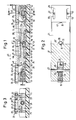
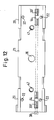
- a circular retaining washer 12 is fastened with fastening screws 13 on a snow sliding board 11, the longitudinal direction of which is approximately perpendicular to the plane of the drawing in FIG. 1, which carries a threaded bore 14 in the center, coaxial with a cylindrical spring receiving space 16 is provided, in which a prestressed helical compression spring 44 is arranged.
- a board plate 17 extending in the longitudinal direction 45 of the boot is screwed to the holding disc 12 and thus to the snow sliding board 11.
- the board plate 17 according to FIG. 11 has radial depressions 20 arranged on a circle, which have an angular spacing of 10 ° and in which the radial projections 15 of the holding disk 12 can engage in a form-locking manner from below.
- a large washer 19 is arranged in a recess 46.
- Helical compression spring 44 is supported at the bottom on the holding disk 12 and presses against the board plate 17 from below.
- a shoe plate 21 is provided in parallel and essentially in alignment therewith, which in the front and rear region has guide pins 22 screwed into it from above and protruding downwards, which according to FIGS. 3 and 9 have partially circular circumferential recesses from above 23 engage the board plate 17.
- the center of the circular circumferential recesses 23 lies on the vertical axis 33, which also represents the central axis of the central pin 18 and the threaded bore 14.
- the board plate 17 and the shoe plate 21 also extend in the front and rear area at a greater distance from the plate ends than the guide pins 22 connecting pins 24 with partial ball heads 25 at both ends.
- the upper partial ball heads 25 are arranged in complementarily spherical recesses 47 in the shoe plate 21, the connecting pins 24 being guided downwards through a bore 48 adjoining the recess 47 into a cavity 49 in the board plate 17.
- the lower partial ball heads 25 are in corresponding complementary recesses of swivel cams 26 arranges that are pivotally attached to the board plate 17 about transverse axes 27 and are acted upon by a release spring 28 on the side of the axis of rotation 27 facing away from the recesses 50, which spring is arranged in a cavity of the board plate 17 parallel to the longitudinal direction 45 and on that of the swivel cam 26 opposite side is supported by adjusting screws 51 accessible from the outside.
- a flat abutment 52 at the inner end of the release spring 28 acts on a correspondingly flat side of the pivoting cams 26, as a result of which they are held in the position shown in FIGS. 1 to 3.
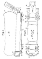
- a boot 31 is arranged on the board plate 21, which is held in firm connection with the shoe plate 21 by a front boot holding means 43 in the form of a strap and by a rear boot holding means 40 in the form of a releasable hold-down device.
- an adjusting screw 30 extends through the shoe plate 21 from front to back. It has a right-hand thread 30 'in the area of the rear sliding plate 29' and a left-hand thread 30 'in the area of the front sliding plate 29, which cooperate with corresponding threads in nuts 54 of the sliding plates 29. From the front the adjusting screw 30 is accessible so that by inserting a screwdriver into the screwdriver slot provided there a rotation of the adjusting screw 30 and thus an opposite adjustment of the sliding plates 29 can be brought about.
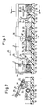
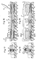
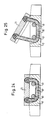
- FIG. 6 and 7 show how the binding according to FIG. 1 can tilt laterally by an angle ⁇ in the case of excessive forces acting on the leg of the user.
- the pivoting cams 26 are pivoted upward via the connecting pins 24, the trigger springs 28 being compressed accordingly.
- the right guide pins 22 are supported on the bottom of the corresponding circumferential recesses 23.
- the tilt angle ⁇ here is smaller than the tilt angle ⁇ according to FIG. 7, but this flexibility is sufficient to dampen dangerous impacts.
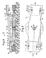
- FIG. 9 finally shows how the shoe plate 21 pivots about the vertical axis 33 relative to the board plate 17 when a shock-like and dangerous torsional moment acts on the boot.
- the plates can rotate at an angle ⁇ of about 10 ° resiliently relative to each other, the shoe plate 21 is rotatably guided via the guide pin 22 in the circumferential recesses 23 and through the head 18 'of the central pin 18 in the central bore 36 of the shoe plate 21. Since the guide pins 22 according to FIG. 3 bear against the obliquely rising areas of the circumferential recesses 23 in the event of such a torsion, this results in an additional tensioning of the pivot cams 26, so that the restoring torque is increased accordingly.
- the exemplary embodiment according to FIGS. 13 to 15 differs from that according to FIGS. 1 to 3 only in that instead of the connecting pin 24 with the partial ball heads 25 flat tabs 32 with elongated holes 38 are provided at both ends, into which transverse pin 55 or 56 engage the shoe plate 21 or the swivel cam 26.
- flat tabs 32 with elongated holes 38 are provided at both ends, into which transverse pin 55 or 56 engage the shoe plate 21 or the swivel cam 26.
- the mobility corresponds to that of the connecting pin 24 according to FIG. 1.
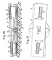
- FIGS. 16 to 19 shows a further possibility for the elastic safety connection of the board plate 17 with the shoe plate 21.
- elastic straps 35 are provided around longitudinal bolts 59, 60 in shoe plate 21 or board plate 17, which normally hold shoe plate 21 in the position shown in FIGS. 16 and 17.
- the shoe plate 21 can tilt sideways analogously to the exemplary embodiment according to FIGS. 6, 7 with elastic stretching of the elastic bands 35.
- the head 18 'of the central pin 18 engages in the central bore 36 of the cleat 21.
- guide projections 37 are provided on the underside of the shoe plate 21, which engage in recesses 39 from above, which are also shown in FIG. 19.
- These recesses 39 represent locking recesses for the guide projections 37, from which they at least partially emerge during a torsion according to FIG. 21, the elastic bands 35 being tensioned accordingly.
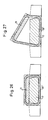
- FIG. 20 shows how the elastic bands 35 deform when the shoe plate 21 is tilted forward.
- elastic bands 35 designed as closed loops can also be provided on each side of the central longitudinal axis of the two plates 17, 21.
- an elastic band 35 ⁇ surrounds the entirety of board plate 17 and shoe plate 21 in a certain area in front of and behind the vertical axis 33. In this way too, an elastic tilting according to FIG. 27 can be achieved as well as a tilting after front or back or a twist.
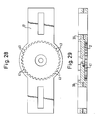
- circumferential teeth 42 are provided on the circular holding disc 12 radially on the outside (FIG. 30), which cooperate with circumferential recesses 41 provided on the underside of the board plate 17 on the underside of the board plate 17 according to FIGS. 28, 29, by the circumferential teeth 42 each engage in the associated circumferential recesses 41 after the rotational position.
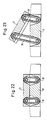
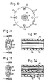
- FIGS. 31, 32 on the one hand and 33, 34 on the other hand it is shown how, instead of the loop-like elastic bands 35 which are guided around the longitudinal bolts 59, 60, block-like elastic bodies 35 ′′′ can also be used, provided they have sufficient elasticity.
- the longitudinal bolts 59, 60 are passed through the elastic body 35 hin barn in the longitudinal direction.
- 35 and 36 show a binding analogous to FIG. 16, but with the boot 31 being inserted in an elastic holder 62 which is an integral part of the shoe plate 21.
- the holder 62 can have further shoe holding means, not shown, which detachably hold the boot 31 on the shoe plate 21.
- the holder 62 can form an integrating component of the boot 31, which is thereby structurally combined with the shoe plate 21.
- the shoe plate 21 should be detachable from the board plate 17, for example by pulling out longitudinal bolts 59.
- the inclination of the guide plate 21 can be adjusted in the desired manner in the exemplary embodiment according to FIGS. 1 to 15 by means of the guide pins 22 screwable from above.
Landscapes
- Footwear And Its Accessory, Manufacturing Method And Apparatuses (AREA)
- Holders For Apparel And Elements Relating To Apparel (AREA)
- Orthopedics, Nursing, And Contraception (AREA)
- Aiming, Guidance, Guns With A Light Source, Armor, Camouflage, And Targets (AREA)
Priority Applications (1)
| Application Number | Priority Date | Filing Date | Title |
|---|---|---|---|
| AT90104744T ATE94774T1 (de) | 1989-06-09 | 1990-03-13 | Schneegleitbrett mit zwei bindungen. |
Applications Claiming Priority (2)
| Application Number | Priority Date | Filing Date | Title |
|---|---|---|---|
| DE3918939A DE3918939A1 (de) | 1989-06-09 | 1989-06-09 | Schneegleitbrett mit zwei bindungen |
| DE3918939 | 1989-06-09 |
Publications (3)
| Publication Number | Publication Date |
|---|---|
| EP0401477A2 true EP0401477A2 (fr) | 1990-12-12 |
| EP0401477A3 EP0401477A3 (fr) | 1991-07-24 |
| EP0401477B1 EP0401477B1 (fr) | 1993-09-22 |
Family
ID=6382468
Family Applications (1)
| Application Number | Title | Priority Date | Filing Date |
|---|---|---|---|
| EP90104744A Expired - Lifetime EP0401477B1 (fr) | 1989-06-09 | 1990-03-13 | Surf de neige avec deux fixations de chaussure |
Country Status (6)
| Country | Link |
|---|---|
| US (1) | US5044656A (fr) |
| EP (1) | EP0401477B1 (fr) |
| JP (1) | JPH0326283A (fr) |
| AT (1) | ATE94774T1 (fr) |
| CA (1) | CA2012630A1 (fr) |
| DE (2) | DE3918939A1 (fr) |
Cited By (4)
| Publication number | Priority date | Publication date | Assignee | Title |
|---|---|---|---|---|
| EP0525580A1 (fr) * | 1991-07-31 | 1993-02-03 | Gaston Haldemann | Dispositif de fixation d'une chaussure sur un surf à neige |
| FR2702388A1 (fr) * | 1993-03-11 | 1994-09-16 | Michel Robert | Fixation de sécurité avec réglages angulaires pour surf des neiges. |
| FR2775613A1 (fr) * | 1998-03-06 | 1999-09-10 | Salomon Sa | Ensemble de retenue non declenchable d'une chaussure sur une planche de glisse |
| WO2012075991A3 (fr) * | 2010-12-07 | 2012-09-20 | Otto-Von-Guericke-Universität Magdeburg | Fixation de sécurité pour les sports de glisse alpins |
Families Citing this family (24)
| Publication number | Priority date | Publication date | Assignee | Title |
|---|---|---|---|---|
| US5577756A (en) * | 1993-07-19 | 1996-11-26 | Caron; Jeffrey E. | Snowboard binding system |
| US5538272A (en) * | 1994-03-21 | 1996-07-23 | Peart; Stephen | Tunable snowboard |
| US6352268B1 (en) | 1994-09-19 | 2002-03-05 | Stephen Peart | Snowboard with transitioning convex/concave curvature |
| US5660410A (en) * | 1994-12-09 | 1997-08-26 | Device Manufacturing Corporation | Strapless boot binding for snowboards |
| US6126179A (en) * | 1995-01-20 | 2000-10-03 | The Burton Corporation | Method and apparatus for interfacing a snowboard boot to a binding |
| US6460871B1 (en) | 1995-01-20 | 2002-10-08 | The Burton Corporation | Step-in snowboard binding |
| US5722680A (en) | 1996-05-29 | 1998-03-03 | The Burton Corporation | Step-in snowboard binding |
| US5690351A (en) | 1995-07-21 | 1997-11-25 | Karol; Chris | Snowboard binding system |
| TW340099B (en) * | 1995-11-29 | 1998-09-11 | Suzuki Co Ltd | Scooter-type vehicle |
| US5813689A (en) * | 1996-05-17 | 1998-09-29 | Brigham Young University | Binding assembly for a snow board |
| US6123354A (en) * | 1996-05-29 | 2000-09-26 | Laughlin; James | Step-in snowboard binding |
| US6189911B1 (en) | 1997-01-11 | 2001-02-20 | Caron Alpine Technologies, Inc. | Snow board binding system |
| US5901975A (en) * | 1997-03-18 | 1999-05-11 | Eric T. Phipps | Vertically flexible snowboard binding |
| US6575490B1 (en) | 2000-04-28 | 2003-06-10 | The Burton Corporation | Adjustable pad for foot binding |
| US7086662B2 (en) * | 2001-01-30 | 2006-08-08 | Trak Sports Usa, Inc. | Ski binding |
| FR2834909B1 (fr) * | 2002-01-18 | 2004-04-09 | Emery Sa | Perfectionnement pour dispositif de retenue d'une chaussure sur une planche de glisse sur neige du type surf |
| US7976045B2 (en) * | 2006-09-21 | 2011-07-12 | Felt Racing, Llc | Bicycle front fork assembly |
| US7571920B2 (en) * | 2006-09-21 | 2009-08-11 | Felt Racing, Llc | Bicycle front fork assembly |
| DE102008051334B3 (de) * | 2008-10-15 | 2010-05-06 | Otto-Von-Guericke-Universität Magdeburg | Sicherheitsbindung für ein mobiles Sportgerät |
| US9016714B2 (en) | 2009-04-30 | 2015-04-28 | Jf Pelchat Inc. | Binding system for recreational board |
| WO2010124382A1 (fr) * | 2009-04-30 | 2010-11-04 | Pelchat Jean-Francois | Système de fixation pour une planche de loisir |
| WO2011044067A1 (fr) * | 2009-10-05 | 2011-04-14 | Jacob Bender | Dispositifs de fixation pour le pied |
| USD689971S1 (en) | 2012-03-15 | 2013-09-17 | NOW Snowboarding Inc. | Snowboard binding |
| US9687725B1 (en) | 2016-03-22 | 2017-06-27 | Motion Water Sports, Inc. | Binding assembly for sport board having angled connector receptacles |
Family Cites Families (21)
| Publication number | Priority date | Publication date | Assignee | Title |
|---|---|---|---|---|
| DE2031018C3 (de) * | 1970-06-23 | 1979-02-08 | Marker, Hannes, 8100 Garmisch-Partenkirchen | Sicherheits-Skibindungssystem |
| US3825274A (en) * | 1970-11-17 | 1974-07-23 | Nat Recreation Ind | Ski binding with automatic boot-to-ski return |
| DE2255406A1 (de) * | 1972-11-11 | 1974-05-16 | Wolf Dieter Hellmann | Vorrichtung zur zuordnung der fussaufstellflaeche zu skiern |
| AT325486B (de) * | 1973-06-15 | 1975-10-27 | Smolka & Co Wiener Metall | Skibindung |
| DE2348905A1 (de) * | 1973-09-28 | 1975-04-10 | Gerhard Witting | Ausloesebindung |
| US3871674A (en) * | 1974-06-03 | 1975-03-18 | Jr Thomas C Bunn | Ski safety device |
| FR2309256A1 (fr) * | 1975-05-02 | 1976-11-26 | Mitchell Sa | Fixation de securite pour ski |
| DE2526822A1 (de) * | 1975-06-16 | 1976-12-30 | Ver Baubeschlag Gretsch Co | Sicherheitsskibindung |
| US4065151A (en) * | 1976-02-27 | 1977-12-27 | National Recreation Industries, Inc. | Retractable ski binding |
| US4067593A (en) * | 1976-04-27 | 1978-01-10 | Earl Arthur W | Adjustable platform ski binding mount |
| DE2752206C3 (de) * | 1977-11-23 | 1986-03-27 | Bernhard 5500 Trier Kirsch | Sohlenplatte für Skibindungen |
| US4165887A (en) * | 1977-12-01 | 1979-08-28 | Bunn Thomas C Jr | Controlled excursion ski binding with safety release |
| DE2828633A1 (de) * | 1978-06-29 | 1980-01-10 | Marker Hannes | Sicherheits-skibindung |
| DE2839965A1 (de) * | 1978-09-14 | 1980-04-03 | Voitl & Cie | Zwischenglied zwischen ski und skibindung |
| AT385667B (de) * | 1984-11-15 | 1988-05-10 | Head Sportgeraete Gmbh | Ski fuer die verwendung mit einer auflageplatte fuer die aufnahme von bindungsteilen |
| US4741550A (en) * | 1985-11-15 | 1988-05-03 | David Dennis | Releasable binding system for snowboarding |
| US4652007A (en) * | 1985-11-15 | 1987-03-24 | David Dennis | Releasable binding system for snowboarding |
| AT386538B (de) * | 1986-03-27 | 1988-09-12 | Tyrolia Freizeitgeraete | Sicherheitsskibindung |
| IT1215027B (it) * | 1986-12-03 | 1990-01-31 | Longoni Andrea | Sistema di inclinazione laterale variabile per supporto ed aggancio di scarponi da sci e similari su surf da neve (snow board) ed affini, atto a consentire inclinazioni trasversali del piano di appoggio dello scarpone rispetto al suo senso longitudinale ed alla superficie dell'attrezzo. |
| CH672432A5 (fr) * | 1987-03-27 | 1989-11-30 | Hansruedi Naepflin | |
| IT1219163B (it) * | 1988-03-30 | 1990-05-03 | Giarretta Adriano Prestipino | Attacchi di sicurezza per tavola da neve surf |
-
1989
- 1989-06-09 DE DE3918939A patent/DE3918939A1/de not_active Withdrawn
-
1990
- 1990-03-13 DE DE90104744T patent/DE59002800D1/de not_active Expired - Fee Related
- 1990-03-13 EP EP90104744A patent/EP0401477B1/fr not_active Expired - Lifetime
- 1990-03-13 AT AT90104744T patent/ATE94774T1/de not_active IP Right Cessation
- 1990-03-20 CA CA002012630A patent/CA2012630A1/fr not_active Abandoned
- 1990-03-29 US US07/501,691 patent/US5044656A/en not_active Expired - Fee Related
- 1990-06-11 JP JP2152527A patent/JPH0326283A/ja active Pending
Cited By (4)
| Publication number | Priority date | Publication date | Assignee | Title |
|---|---|---|---|---|
| EP0525580A1 (fr) * | 1991-07-31 | 1993-02-03 | Gaston Haldemann | Dispositif de fixation d'une chaussure sur un surf à neige |
| FR2702388A1 (fr) * | 1993-03-11 | 1994-09-16 | Michel Robert | Fixation de sécurité avec réglages angulaires pour surf des neiges. |
| FR2775613A1 (fr) * | 1998-03-06 | 1999-09-10 | Salomon Sa | Ensemble de retenue non declenchable d'une chaussure sur une planche de glisse |
| WO2012075991A3 (fr) * | 2010-12-07 | 2012-09-20 | Otto-Von-Guericke-Universität Magdeburg | Fixation de sécurité pour les sports de glisse alpins |
Also Published As
| Publication number | Publication date |
|---|---|
| US5044656A (en) | 1991-09-03 |
| ATE94774T1 (de) | 1993-10-15 |
| EP0401477B1 (fr) | 1993-09-22 |
| DE59002800D1 (de) | 1993-10-28 |
| EP0401477A3 (fr) | 1991-07-24 |
| CA2012630A1 (fr) | 1990-12-09 |
| JPH0326283A (ja) | 1991-02-04 |
| DE3918939A1 (de) | 1990-12-13 |
Similar Documents
| Publication | Publication Date | Title |
|---|---|---|
| EP0401477B1 (fr) | Surf de neige avec deux fixations de chaussure | |
| EP0396133A1 (fr) | Fixation déclenchable de snowboard, comportant une plaque | |
| DE2511571A1 (de) | Schi-sicherheitsbindungssystem | |
| DE60132040T2 (de) | Schuhbindung für Snowboard oder Rollbrett | |
| DE4034099A1 (de) | Sicherheitsbindung fuer snowboards | |
| DE4142390C2 (de) | Sicherheitsbindung für Sprungski | |
| DE2138781A1 (de) | Sicherheits Skibindung | |
| DE3838045A1 (de) | Pedal mit sicherheitseinrichtung fuer ein rennfahrrad | |
| EP3906980B1 (fr) | Talonnière pour une fixation de ski | |
| DE3725709A1 (de) | Vorderbacken fuer sicherheits-skibindungen | |
| DE1478140C3 (de) | Vorderbacken für Sicherheits-Skibindungen | |
| DE2324776A1 (de) | Sicherheits-skibindung | |
| DE2217273A1 (de) | Auslösende Skibindung für den Abfahrtslauf | |
| EP0394380B1 (fr) | Fixation de securite pour ski | |
| DE4435960C2 (de) | Snowboardbindung | |
| DE2806937C2 (de) | Wahlweise für Abfahrt und für Touren umstellbare Auslöseskibindung | |
| DE2528017C3 (de) | Verriegelungsorgan für eine Skibindung | |
| DE2824581A1 (de) | Skisicherheitsbuegel | |
| DE1956653A1 (de) | Vorderbacken fuer Sicherheits-Skibindungen | |
| DE698211C (de) | Befestigungsvorrichtung fuer Schneeschuhe mit einer abnehmbaren Platte | |
| EP4257212B1 (fr) | Unité de talon pour une fixation de planche de glisse dotée d'un déclenchement mz par l'intermédiaire d'une came | |
| DE1145070B (de) | Sicherheitsskibindung mit ausschwenkbarem Vorderbacken | |
| EP0346509A1 (fr) | Planche à voile | |
| AT373163B (de) | Vorrichtung zum tourengehen fuer eine sicherheitsskibindung | |
| EP0088430A2 (fr) | Dérive pour planche à voile |
Legal Events
| Date | Code | Title | Description |
|---|---|---|---|
| PUAI | Public reference made under article 153(3) epc to a published international application that has entered the european phase |
Free format text: ORIGINAL CODE: 0009012 |
|
| AK | Designated contracting states |
Kind code of ref document: A2 Designated state(s): AT CH DE FR IT LI |
|
| PUAL | Search report despatched |
Free format text: ORIGINAL CODE: 0009013 |
|
| AK | Designated contracting states |
Kind code of ref document: A3 Designated state(s): AT CH DE FR IT LI |
|
| RHK1 | Main classification (correction) |
Ipc: A63C 9/08 |
|
| 17P | Request for examination filed |
Effective date: 19910927 |
|
| 17Q | First examination report despatched |
Effective date: 19930127 |
|
| GRAA | (expected) grant |
Free format text: ORIGINAL CODE: 0009210 |
|
| AK | Designated contracting states |
Kind code of ref document: B1 Designated state(s): AT CH DE FR IT LI |
|
| PG25 | Lapsed in a contracting state [announced via postgrant information from national office to epo] |
Ref country code: IT Free format text: LAPSE BECAUSE OF FAILURE TO SUBMIT A TRANSLATION OF THE DESCRIPTION OR TO PAY THE FEE WITHIN THE PRE;WARNING: LAPSES OF ITALIAN PATENTS WITH EFFECTIVE DATE BEFORE 2007 MAY HAVE OCCURRED AT ANY TIME BEFORE 2007. THE CORRECT EFFECTIVE DATE MAY BE DIFFERENT FROM THE ONE RECORDED.SCRIBED TIME-LIMIT Effective date: 19930922 |
|
| REF | Corresponds to: |
Ref document number: 94774 Country of ref document: AT Date of ref document: 19931015 Kind code of ref document: T |
|
| REF | Corresponds to: |
Ref document number: 59002800 Country of ref document: DE Date of ref document: 19931028 |
|
| ET | Fr: translation filed | ||
| PLBE | No opposition filed within time limit |
Free format text: ORIGINAL CODE: 0009261 |
|
| STAA | Information on the status of an ep patent application or granted ep patent |
Free format text: STATUS: NO OPPOSITION FILED WITHIN TIME LIMIT |
|
| 26N | No opposition filed | ||
| PGFP | Annual fee paid to national office [announced via postgrant information from national office to epo] |
Ref country code: AT Payment date: 19950324 Year of fee payment: 6 |
|
| PGFP | Annual fee paid to national office [announced via postgrant information from national office to epo] |
Ref country code: CH Payment date: 19950418 Year of fee payment: 6 |
|
| PGFP | Annual fee paid to national office [announced via postgrant information from national office to epo] |
Ref country code: DE Payment date: 19950427 Year of fee payment: 6 |
|
| PG25 | Lapsed in a contracting state [announced via postgrant information from national office to epo] |
Ref country code: AT Effective date: 19960313 |
|
| PGFP | Annual fee paid to national office [announced via postgrant information from national office to epo] |
Ref country code: FR Payment date: 19960318 Year of fee payment: 7 |
|
| PG25 | Lapsed in a contracting state [announced via postgrant information from national office to epo] |
Ref country code: LI Effective date: 19960331 Ref country code: CH Effective date: 19960331 |
|
| REG | Reference to a national code |
Ref country code: CH Ref legal event code: PL |
|
| PG25 | Lapsed in a contracting state [announced via postgrant information from national office to epo] |
Ref country code: DE Effective date: 19961203 |
|
| PG25 | Lapsed in a contracting state [announced via postgrant information from national office to epo] |
Ref country code: FR Free format text: LAPSE BECAUSE OF NON-PAYMENT OF DUE FEES Effective date: 19971128 |
|
| REG | Reference to a national code |
Ref country code: FR Ref legal event code: ST |