EP0401751B1 - Robot grimpeur se déplaçant le long d'une construction en chevalet, notamment d'un mât pour des lignes électriques aériennes à haute tension - Google Patents
Robot grimpeur se déplaçant le long d'une construction en chevalet, notamment d'un mât pour des lignes électriques aériennes à haute tension Download PDFInfo
- Publication number
- EP0401751B1 EP0401751B1 EP90110617A EP90110617A EP0401751B1 EP 0401751 B1 EP0401751 B1 EP 0401751B1 EP 90110617 A EP90110617 A EP 90110617A EP 90110617 A EP90110617 A EP 90110617A EP 0401751 B1 EP0401751 B1 EP 0401751B1
- Authority
- EP
- European Patent Office
- Prior art keywords
- robot
- pole
- clamping finger
- slide
- main
- Prior art date
- Legal status (The legal status is an assumption and is not a legal conclusion. Google has not performed a legal analysis and makes no representation as to the accuracy of the status listed.)
- Expired - Lifetime
Links
- 230000009194 climbing Effects 0.000 title claims description 16
- 230000000903 blocking effect Effects 0.000 claims 1
- 230000006870 function Effects 0.000 description 2
- 238000013459 approach Methods 0.000 description 1
- 230000006399 behavior Effects 0.000 description 1
- 239000012212 insulator Substances 0.000 description 1
- 235000000396 iron Nutrition 0.000 description 1
- 230000000750 progressive effect Effects 0.000 description 1
Images


Classifications
-
- B—PERFORMING OPERATIONS; TRANSPORTING
- B62—LAND VEHICLES FOR TRAVELLING OTHERWISE THAN ON RAILS
- B62D—MOTOR VEHICLES; TRAILERS
- B62D57/00—Vehicles characterised by having other propulsion or other ground- engaging means than wheels or endless track, alone or in addition to wheels or endless track
- B62D57/02—Vehicles characterised by having other propulsion or other ground- engaging means than wheels or endless track, alone or in addition to wheels or endless track with ground-engaging propulsion means, e.g. walking members
- B62D57/024—Vehicles characterised by having other propulsion or other ground- engaging means than wheels or endless track, alone or in addition to wheels or endless track with ground-engaging propulsion means, e.g. walking members specially adapted for moving on inclined or vertical surfaces
Definitions
- the invention concerns a robot apt to climb along a trestle structure, particularly the trestle of a pole for high-voltage overhead electric lines, in order to carry work-tools from the base to the top of the pole. More specifically, the robot according to the invention has been studied to carry up to the pole brackets for instance an equipment to wash the insulator chains, of the type described in EP-A1-0360012, filed by the same Applicant. For this reason, and also to make the description shorter, reference will be made hereinafter to the trestle structure of an electric line pole; it is however understood that the robot according to the invention can easily be used to perform different operations, on trestle structures other than those indicated hereabove, or on fixed or temporary trestlework or tubular scaffolding.
- a movable robot which works in an environment of this kind, known as a partially structured environment , must have a structure which be able to overcome these difficulties.
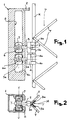
- the gripping hand 3 comprises two pairs of clamping fingers 3a and 3b, essentially in the form of hooks, and a dihedral bearing seat 3c; onto the seat 3c bears the corner edge Mc of the angle bar forming the upright M, while the hook ends of the clamping fingers 3a, 3b, hold onto the free edges Ma and Mb of its sides.
- the slide 7 moves from the bottom to the top end of the guide 8.
- the sensor 2 scans the surface of the upright M and, as said, supplies the consent signal to stop the slide 7 in a position along said upright where there are no obstacles, represented for example by the connections of the ledgers T or by the joints of the angle bars forming the upright.
- the positions - or, rather, the coordinates of the positions - along the trestle structure, where obstacles are detected by the sensor 2, as well as the positions in which the gripping hand 3 is authorized by the sensor to hold onto said structure, are stored into the processing unit so as to be subsequently used again for positioning the other gripping hand 4 in the climbing up step or, viceversa, for positioning both hands 3 and 4 as the robot climbs down the pole.
- this downclimb is controlled by the processing unit thanks to the position data acquired and stored during the climbing up step, - as already said - or else by placing another position sensor (not shown in the drawings) in correspondence of the bottom end of the body 1 of the robot.
- the body 1 can thus reach the position shown in full lines in fig. 5, according to the new inclination of the upright M′. In this position, the arm 5a can be moved forward to cause the hand 4 to grip onto the upright M.
- the processing unit substantially produces a coordinate rotation of the cores 6, 6a - and thereby a shifting of the slides 7, 7a, and of the arms 5, 5a - such as to prevent any interference of the body 1 with the pole structure and, at the same time, keep the hands 3 and 4 always parallel and in a correct gripping position onto the pole upright.
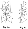
- a slide 17 is slidably mounted on the body 10 of the robot and gripping hands are associated both to the body 10 and to the slide 17.
- gripping hands are associated both to the body 10 and to the slide 17.
- use is made of two separate gripping hands 13, 13a, associated to the slide 17 and, respectively, of two gripping hands 14, 14a, associated to the body 1.
- At least one of the two hands of each pair is mounted on a slider movable lengthwise, that is, parallely to the motion direction of the slide 7; thanks to this assembly, the two hands of each pair are apt to move one in respect of the other, with possibility to draw close or apart.
- the gripping hand 14a is mounted on a slider (better described hereinafter) slidable into a guide 11 of the body 10, while the gripping hand 13 is mounted on a slider sliding into a guide 12 of the slide 17.
- This arrangement allows said hands to each grip onto a different ledger T, the ledgers normally being quite spaced apart and, furthermore, at varying mutual distances along the pole height.
- a position sensor 17A is associated to the upper end of the slide 17, and is apt to detect and store the positions of the ledgers T and possibly also their inclination.
- a second sensor 10A is associated to the upper end of the body 10.
- At least the general data and/or part of the position coordinates of the trestle configuration can be previously stored in the memory of the processing unit, starting from the data resulting from the pole project design.
- the angle bars forming the ledgers are positioned with a first flange on the plane of the pole surface and with a second flange perpendicular to said surface. Furthermore, to realize a proper crossing of the ledgers, the second flange of a set of such ledgers - all having a first equal inclination - projects outwardly of the pole, while the second flange of another set of such ledgers - all having a second equal inclination - projects inwardly of the pole, so as to properly cross with the first set. As described more clearly hereinafter, with reference to the details of figs. 8a to 8f, the hands of this robot are apt to grip onto the horizontal flanges of the ledgers T projecting outwardly of the pole.
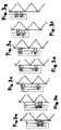
- this robot holds with the lower hand 14a of the body 10 onto the ledger T1, with the upper hand 14 of the body 10 and with the lower hand 13a of the slide 17 onto the ledger T2, and with the upper hand 13 of the slide 17 onto the ledger T3.
- the body 10 slides upward until its sensor 10A - which detects the presence of the ledger T3 - causes the upper hand 14 to stop in correspondence of said ledger T3 and hold onto the same (figs. 6c and 7c).
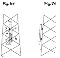
- the body 10 being thus anchored, the gripping hand 14a is caused to slide along the guide 11 up to stopping in correspondence of the ledger T2 and hold onto the same (figs. 6d and 7d).
- the successive step (not shown) provides for: the release of hands 13, 13a; the upward shifting of the slide 17 until the sensor 17A detects the ledger T4; the gripping of the upper hand 13 onto the ledger T4; the further sliding of the hand 13 in respect of its guide 12 and, consequently, the simultaneous shifting, by reaction, of the slide 17, up to carrying the hand 13a in correspondence of the ledger T3, whereon it grips.
- This position corresponds to that shown in figs. 6a and 7a, except that the robot is now at a higher level along the pole.
- the lower hand 13a of the slide 17 is movable into a short transversal guide 12a, substantially perpendicular to the guide 12 and shown very diagrammatically in fig. 6c.
- This transversal movement is used just before operating the slide, or also while the body 10 is moving upward (in any case, when the gripping hands of the body 10 are disengaged from the respective ledgers T), in order to control the perfect vertical alignment of the robot. The same operation can be performed when the robot climbs down the pole.
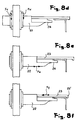
- FIGS 8 show, quite diagrammatically, a possible embodiment of a gripping hand to be used in a robot according to the embodiment of figures 5 and 6.
- This hand comprises:
Landscapes
- Engineering & Computer Science (AREA)
- Chemical & Material Sciences (AREA)
- Combustion & Propulsion (AREA)
- Transportation (AREA)
- Mechanical Engineering (AREA)
- Manipulator (AREA)
Claims (14)
- Robot grimpeur, mobile le long d'une structure en chevalet, en particulier la structure en chevalet d'un poteau pour lignes électriques aériennes à haute tension, ledit poteau comportant une pluralité de barres d'angle formant des montants d'inclinaison variable et formant également des traverses espacées les unes des autres de distances variables, ledit robot comprenant :a) un corps principal (1; 10)b) quatre moyens de doigts de serrage (3a, 3b, 4a, 4b; 13, 13a, 14, 14a), chacun pour serrer une barre d'angle de ladite pluralité de barres d'angle (M, T, T1, T2, T3)c) des moyens de déplacement (5, 6, 7, 5a, 6a, 7a; 17, 22, 23, 24), pour déplacer chacun desdits moyens de doigts de serrage selon un axe de déplacement principal, sensiblement vertical et parallèle à la surface du poteau et, respectivement, selon un axe transversal sensiblement perpendiculaire à la surface du poteau;d) au moins un capteur de position (2; 17A) pour acquérir des données sur la position des barres d'angle et/ou les distances variables entre les traverses,e) un système de traitement, qui commande lesdits moyens de déplacement, en utilisant également les signaux émis par lesdits capteurs,caractérisé en ce quef) une coulisse principale (7, 17) est montée de manière à pouvoir se déplacer le long dudit corps principal (1; 10), parallèlement audit axe de déplacement principal,g) deux (4a, 4b; 14, 14a) desdits moyens de doigts de serrage sont montés sur ledit corps principal (1; 10), au moins l'un (4a, 4b; 14a) d'eux pouvant être ajusté en position relativement au corps principal, eth) deux autres (3a, 3b; 13, 13a) desdits moyens de doigts de serrage sont montés sur ladite coulisse principale (7; 17), au moins l'un (3a, 3b; 13, 13a) d'eux pouvant être ajusté en position relativement à la coulisse principale,i) lesdits capteurs de position (2, 17A) comprennent des moyens pour acquérir des données sur l'inclinaison variable de la surface du poteau,j) de sorte que le robot monte et descende le long de la structure du poteau et sur sa surface à inclinaison variable, en bloquant tour à tour sur ladite structure du poteau les deux moyens de doigts de serrage associés au corps principal ou, respectivement, les deux moyens de doigts de serrage associés à la coulisse principale, tandis que les deux autres moyens de doigts de serrage sont libres de se déplacer simultanément le long de la structure du poteau.
- Robot selon la revendication 1, dans lequel lesdits moyens de doigts de serrage comprennent un siège d'appui dièdre (3c) et deux paires de doigts en crochets (3a, 3b, 4a, 4b) les doigts de chaque paire étant positionnés sur les deux côtés dudit siège dièdre, ce dernier étant apte à recevoir le coin (Mc) de la barre d'angle formant un montant (M) de la structure en chevalet, et les deux doigts en crochets étant aptes à serrer les bords opposés (M, Mb) de ladite barre d'angle.
- Robot selon la revendication 2, dans lequel ledit siège d'appui dièdre (3c) est supporté par la tête d'un piston se déplaçant perpendiculairement à ladite barre d'angle formant un montant, et lesdits doigts en crochets sont montés à rotation dans des directions opposées sur le boîtier logeant ledit piston.
- Robot selon la revendication 1, dans lequel lesdits moyens de déplacement comprennent un bras (5, 5a) supportant lesdits moyens de doigts de serrage, ledit bras (5, 5a) étant monté de manière à coulisser dans un siège correspondant d'un noyau de support (6, 6a), selon ledit axe transversal (Y-Y) perpendiculaire à la surface du poteau.
- Robot selon la revendication 4, dans lequel ledit noyau de support (6, 6a) est à son tour monté à rotation sur un axe horizontal (X-X), transversal audit bras (5, 5a) supportant les moyens de doigts de serrage.
- Robot selon la revendication 5, dans lequel ledit noyau de support (6, 6a) est monté sur ladite coulisse mobile (7, 7a) pouvant tourner relativement au corps de support principal (1).
- Robot selon la revendication 1, dans lequel, audit corps de support principal (10) sont associés deux moyens de doigts de serrage (14, 14a) espacés l'un de l'autre, tandis que deux autres moyens de doigts de serrage (13, 13a) sont associés à ladite coulisse principale (17), coulissant relativement au corps de support principal (10).
- Robot selon la revendication 7, dans lequel un moyen de doigt de serrage (14) est monté dans une position fixe du corps de support principal (10), tandis que l'autre moyen de doigt de serrage (14a) est monté sur une coulisse secondaire (20), pouvant coulisser dans un guide sensiblement vertical (11) formé dans ledit corps de support (10).
- Robot selon la revendication 7, dans lequel un moyen de doigt de serrage (13a) est monté dans une position fixe de la coulisse principale (17) et l'autre moyen de doigt de serrage (13) est monté sur une coulisse secondaire (20), pouvant coulisser dans un guide sensiblement vertical (12) formé dans ladite coulisse principale (17).
- Robot selon la revendication 7, dans lequel au moins un desdits moyens de doigts de serrage (13, 13a, 14, 14a) est en outre monté sur une coulisse secondaire (22), pouvant coulisser dans un guide sensiblement horizontal (21) formé dans ledit corps de support et/ou dans ladite coulisse principale.
- Robot selon la revendication 7, dans lequel lesdits moyens de doigts de serrage comprennent chacun un doigt en crochet (23) pouvant coulisser relativement à un contre-doigt fixe (24) dans ladite direction transversale sensiblement perpendiculaire à la surface du poteau, le contre-doigt (24) étant adapté à former une surface d'appui inférieure pour la face horizontale de la barre d'angle (T) formant une traverse du chevalet du poteau, et le doigt en crochet étant adapté à serrer ladite barre d'angle sur son bord.
- Robot selon la revendication 11, dans lequel le doigt en crochet coulissant (23) et le contre-doigt fixe (24) desdits moyens de doigts de serrage (13, 13a, 14, 14a) sont montés sur un corps (22) qui peut coulisser, également dans ladite direction transversale, relativement à un anneau de support (21).
- Robot selon la revendication 12, dans lequel ledit anneau de support (21) du moyen de doigt de serrage est adapté à tourner sur un axe parallèle à ladite direction transversale.
- Robot selon la revendication 13, dans lequel ledit anneau de support rotatif (21) est monté sur ladite coulisse secondaire (20).
Applications Claiming Priority (2)
| Application Number | Priority Date | Filing Date | Title |
|---|---|---|---|
| IT2082989 | 1989-06-08 | ||
| IT8920829A IT1230248B (it) | 1989-06-08 | 1989-06-08 | Robot arrampicatore, mobile lungo una struttura a traliccio, in particolare di un palo di linea elettrica di alta tensione. |
Publications (2)
| Publication Number | Publication Date |
|---|---|
| EP0401751A1 EP0401751A1 (fr) | 1990-12-12 |
| EP0401751B1 true EP0401751B1 (fr) | 1995-11-02 |
Family
ID=11172666
Family Applications (1)
| Application Number | Title | Priority Date | Filing Date |
|---|---|---|---|
| EP90110617A Expired - Lifetime EP0401751B1 (fr) | 1989-06-08 | 1990-06-05 | Robot grimpeur se déplaçant le long d'une construction en chevalet, notamment d'un mât pour des lignes électriques aériennes à haute tension |
Country Status (5)
| Country | Link |
|---|---|
| US (1) | US5213172A (fr) |
| EP (1) | EP0401751B1 (fr) |
| CA (1) | CA2018489A1 (fr) |
| DE (1) | DE69023278D1 (fr) |
| IT (1) | IT1230248B (fr) |
Cited By (1)
| Publication number | Priority date | Publication date | Assignee | Title |
|---|---|---|---|---|
| CN102621425A (zh) * | 2012-03-31 | 2012-08-01 | 山东鲁能智能技术有限公司 | 水平绝缘子串带电检测机器人 |
Families Citing this family (29)
| Publication number | Priority date | Publication date | Assignee | Title |
|---|---|---|---|---|
| EP0873963A1 (fr) * | 1997-04-25 | 1998-10-28 | Inventio Ag | Entraínement linéaire pour un dispositif de transport |
| ES2161184B1 (es) | 1999-12-28 | 2002-07-01 | Consejo Superior Investigacion | Un dispositivo de un elemento de trabajo con dos grados de movilidad. |
| ES2230953B2 (es) * | 2002-07-16 | 2006-06-16 | Universidad Politecnica De Madrid | Robot paralelo trepador y deslizante para trabajos en estructuras y superficies. |
| US7260499B2 (en) * | 2002-08-20 | 2007-08-21 | Fe Petro Inc. | Fuel delivery system with enhanced functionality and diagnostic capability |
| US20040099478A1 (en) * | 2002-11-27 | 2004-05-27 | Xerox Corporation | Climbing apparatus and method |
| US7086502B2 (en) * | 2004-02-24 | 2006-08-08 | Palo Alto Research Center Incorporated | Transport apparatus and method having conformable gripping capability |
| GB0500619D0 (en) * | 2005-01-13 | 2005-02-23 | Severfield Rowen Plc | Improvements relating to construction |
| US9168963B2 (en) * | 2007-12-28 | 2015-10-27 | The Invention Science Fund I, Llc | Systems and methods employing limbed vehicle and spaced posts |
| US9162719B2 (en) * | 2007-12-28 | 2015-10-20 | The Invention Science Fund I, Llc | Limbed vehicles, systems and methods using same, and post networks on which limbed vehicles travel |
| US20090166105A1 (en) * | 2007-12-28 | 2009-07-02 | Searete Llc | Limbed vehicles, systems and methods using same, and post networks on which limbed vehicles travel |
| FR2929228B1 (fr) * | 2008-03-28 | 2010-06-18 | Thales Sa | Robot grimpeur de poteau. |
| CN102060058B (zh) * | 2009-11-17 | 2013-01-23 | 赵德志 | 驻足爬杆机器人 |
| US8640558B2 (en) * | 2011-09-12 | 2014-02-04 | Honeywell International Inc. | System for the automated inspection of structures at height |
| CN102490804B (zh) * | 2011-11-15 | 2013-02-13 | 西华大学 | 一种越障爬杆机器人 |
| CN103926489B (zh) * | 2014-04-17 | 2015-06-24 | 国家电网公司 | 输电线路零值绝缘子带电检测机器人 |
| JP6410174B2 (ja) * | 2014-10-17 | 2018-10-24 | 本田技研工業株式会社 | 移動ロボット |
| JP6593991B2 (ja) * | 2014-12-25 | 2019-10-23 | 三菱重工業株式会社 | 移動ロボット及び先端ツール |
| CN107310650A (zh) * | 2016-04-26 | 2017-11-03 | 广西大学 | 一种爬杆攀壁两用侦查机器人爬杆机构 |
| GB2553271B (en) * | 2016-07-19 | 2019-03-13 | Kongsberg Ferrotech As | Pipeline maintenance and inspection vehicle |
| CN106258794B (zh) * | 2016-08-31 | 2019-08-09 | 墙煌新材料股份有限公司 | 一种自动立柱机器人 |
| CN108340364B (zh) * | 2017-01-24 | 2020-09-15 | 南京原觉信息科技有限公司 | 爬行机器装置与其部署方法 |
| CN107161230A (zh) * | 2017-05-08 | 2017-09-15 | 江南大学 | 一种自动爬杆机器装置及其方法 |
| CN108945141B (zh) * | 2018-07-11 | 2023-08-15 | 西南交通大学 | 一种攀爬机器人复合足端以及攀爬机器人 |
| CN109367639B (zh) * | 2018-11-15 | 2024-02-23 | 国网湖南省电力有限公司 | 一种爬杆机器人及其应用方法 |
| CN109249366B (zh) * | 2018-11-28 | 2020-09-04 | 惠安县崇武镇阳璐广告设计中心 | 电工用辅助攀爬工具箱 |
| CN109895114B (zh) * | 2019-03-12 | 2024-02-27 | 广东机电职业技术学院 | 一种气动肌肉驱动的多边形结构的攀爬机器人 |
| CN110712208B (zh) * | 2019-10-23 | 2021-06-18 | 长沙理工大学 | 带有子机的变电站巡检机器人及其应用方法 |
| CN113843765A (zh) * | 2021-10-22 | 2021-12-28 | 山西菲特智能装备科技股份有限公司 | 开关室操作机器人任务工具总成 |
| CN118539353B (zh) * | 2024-05-13 | 2025-10-14 | 广州番禺电缆集团有限公司 | 高压电缆维修装置及高压电缆维修方法 |
Family Cites Families (7)
| Publication number | Priority date | Publication date | Assignee | Title |
|---|---|---|---|---|
| US3811320A (en) * | 1973-03-12 | 1974-05-21 | Rockwell International Corp | Surface scaler apparatus |
| SU713752A1 (ru) * | 1978-03-13 | 1980-02-05 | Государственный Научно-Исследовательский Институт Машиноведения Им. Академика А.А.Благонравова | Шагающа машина |
| SU713967A1 (ru) * | 1978-08-10 | 1980-02-05 | Карагандинский Научно-Исследовательский Проектно-Конструкторский Экспериментальный Институт Гипроуглегормаш | Шагающий механизм |
| FR2519576B1 (fr) * | 1982-01-11 | 1985-11-29 | Int Robotic Engineerin | Robot a pattes grimpeur |
| US4637494A (en) * | 1983-11-15 | 1987-01-20 | Kabushiki Kaisha Toshiba | Apparatus for moving carriages along ladders |
| US4660678A (en) * | 1984-09-27 | 1987-04-28 | Spider A/S | Service suspension basket arrangement |
| US4738583A (en) * | 1986-09-30 | 1988-04-19 | The United States Of America As Represented By The Administrator Of The National Aeronautics And Space Administration | Space spider crane |
-
1989
- 1989-06-08 IT IT8920829A patent/IT1230248B/it active
-
1990
- 1990-06-05 EP EP90110617A patent/EP0401751B1/fr not_active Expired - Lifetime
- 1990-06-05 DE DE69023278T patent/DE69023278D1/de not_active Expired - Lifetime
- 1990-06-07 CA CA002018489A patent/CA2018489A1/fr not_active Abandoned
- 1990-06-18 US US07/539,864 patent/US5213172A/en not_active Expired - Fee Related
Cited By (1)
| Publication number | Priority date | Publication date | Assignee | Title |
|---|---|---|---|---|
| CN102621425A (zh) * | 2012-03-31 | 2012-08-01 | 山东鲁能智能技术有限公司 | 水平绝缘子串带电检测机器人 |
Also Published As
| Publication number | Publication date |
|---|---|
| IT1230248B (it) | 1991-10-18 |
| CA2018489A1 (fr) | 1990-12-08 |
| US5213172A (en) | 1993-05-25 |
| IT8920829A0 (it) | 1989-06-08 |
| EP0401751A1 (fr) | 1990-12-12 |
| DE69023278D1 (de) | 1995-12-07 |
Similar Documents
| Publication | Publication Date | Title |
|---|---|---|
| EP0401751B1 (fr) | Robot grimpeur se déplaçant le long d'une construction en chevalet, notamment d'un mât pour des lignes électriques aériennes à haute tension | |
| US20180050448A1 (en) | Live working robot | |
| EP4032660B1 (fr) | Robot de construction et procédé de fixation automatique de blocs de construction contre une paroi verticale | |
| US4657438A (en) | Advancing mechanism and system utilizing same for raising and lowering a work platform | |
| CN111502313A (zh) | 人机协作砌墙机器人及系统 | |
| JP2641750B2 (ja) | 板材折曲げ加工機用マニピュレータおよびこのマニピュレータを備えたロボット装置 | |
| JPH0455276A (ja) | エレベータ塔内機器据付方法およびその装置 | |
| US4228871A (en) | Bracket | |
| US20060157302A1 (en) | Scaffold, and girder intended for such a scaffold, and method for building a scaffold | |
| KR102227995B1 (ko) | 브리지 패널 정렬 시스템 및 방법 | |
| CN212613863U (zh) | 人机协作砌墙机器人及系统 | |
| JP2905750B2 (ja) | ボード把持装置 | |
| CN212613788U (zh) | 人机协作砌墙机器人 | |
| CN214187239U (zh) | 夹爪装置及自动化设备 | |
| CN113369739A (zh) | 一种搭接焊系统及其搭接焊方法 | |
| JPH07328973A (ja) | ロボット用把持装置及びこれを用いた部材把持方法 | |
| US12139976B2 (en) | Stabilization manipulator for moving drilling elements in a drilling rig, manipulation system and drilling rig | |
| JPH01263384A (ja) | 建設作業ロボットによる重量長尺物の据付け方法 | |
| CN111622508A (zh) | 人机协作砌墙机器人及砌墙方法 | |
| CN216175508U (zh) | 一种铝排加工用全自动折弯机 | |
| CN113843561B (zh) | 一种用于搭接焊的辅助装置及系统 | |
| CN110270794B (zh) | 管接头焊接抓取定位装置、焊接方法及热水器 | |
| JPH0764235B2 (ja) | ちょう架線碍子の交換器具及び交換方法 | |
| SU764911A1 (ru) | Стенд дл сборки под сварку | |
| SU1710337A1 (ru) | Манипул тор |
Legal Events
| Date | Code | Title | Description |
|---|---|---|---|
| PUAI | Public reference made under article 153(3) epc to a published international application that has entered the european phase |
Free format text: ORIGINAL CODE: 0009012 |
|
| AK | Designated contracting states |
Kind code of ref document: A1 Designated state(s): CH DE ES FR GB IT LI SE |
|
| 17P | Request for examination filed |
Effective date: 19910511 |
|
| 17Q | First examination report despatched |
Effective date: 19930211 |
|
| GRAA | (expected) grant |
Free format text: ORIGINAL CODE: 0009210 |
|
| AK | Designated contracting states |
Kind code of ref document: B1 Designated state(s): CH DE ES FR GB IT LI SE |
|
| PG25 | Lapsed in a contracting state [announced via postgrant information from national office to epo] |
Ref country code: LI Effective date: 19951102 Ref country code: FR Effective date: 19951102 Ref country code: ES Free format text: THE PATENT HAS BEEN ANNULLED BY A DECISION OF A NATIONAL AUTHORITY Effective date: 19951102 Ref country code: CH Effective date: 19951102 |
|
| REF | Corresponds to: |
Ref document number: 69023278 Country of ref document: DE Date of ref document: 19951207 |
|
| ITF | It: translation for a ep patent filed | ||
| PG25 | Lapsed in a contracting state [announced via postgrant information from national office to epo] |
Ref country code: SE Effective date: 19960202 |
|
| PG25 | Lapsed in a contracting state [announced via postgrant information from national office to epo] |
Ref country code: DE Effective date: 19960203 |
|
| EN | Fr: translation not filed | ||
| REG | Reference to a national code |
Ref country code: CH Ref legal event code: PL |
|
| PGFP | Annual fee paid to national office [announced via postgrant information from national office to epo] |
Ref country code: GB Payment date: 19960603 Year of fee payment: 7 |
|
| PLBE | No opposition filed within time limit |
Free format text: ORIGINAL CODE: 0009261 |
|
| STAA | Information on the status of an ep patent application or granted ep patent |
Free format text: STATUS: NO OPPOSITION FILED WITHIN TIME LIMIT |
|
| 26N | No opposition filed | ||
| PG25 | Lapsed in a contracting state [announced via postgrant information from national office to epo] |
Ref country code: GB Free format text: LAPSE BECAUSE OF NON-PAYMENT OF DUE FEES Effective date: 19970605 |
|
| GBPC | Gb: european patent ceased through non-payment of renewal fee |
Effective date: 19970605 |
|
| PG25 | Lapsed in a contracting state [announced via postgrant information from national office to epo] |
Ref country code: IT Free format text: LAPSE BECAUSE OF NON-PAYMENT OF DUE FEES Effective date: 20050605 |