EP0401783A2 - Dispositif numérique de contrôle d'erreur dans un additionneur binaire comportant des unités à retenue de bloc anticipée - Google Patents
Dispositif numérique de contrôle d'erreur dans un additionneur binaire comportant des unités à retenue de bloc anticipée Download PDFInfo
- Publication number
- EP0401783A2 EP0401783A2 EP90110694A EP90110694A EP0401783A2 EP 0401783 A2 EP0401783 A2 EP 0401783A2 EP 90110694 A EP90110694 A EP 90110694A EP 90110694 A EP90110694 A EP 90110694A EP 0401783 A2 EP0401783 A2 EP 0401783A2
- Authority
- EP
- European Patent Office
- Prior art keywords
- carry
- receive
- coupled
- block
- generator
- Prior art date
- Legal status (The legal status is an assumption and is not a legal conclusion. Google has not performed a legal analysis and makes no representation as to the accuracy of the status listed.)
- Granted
Links
Images


Classifications
-
- G—PHYSICS
- G06—COMPUTING OR CALCULATING; COUNTING
- G06F—ELECTRIC DIGITAL DATA PROCESSING
- G06F7/00—Methods or arrangements for processing data by operating upon the order or content of the data handled
- G06F7/38—Methods or arrangements for performing computations using exclusively denominational number representation, e.g. using binary, ternary, decimal representation
- G06F7/48—Methods or arrangements for performing computations using exclusively denominational number representation, e.g. using binary, ternary, decimal representation using non-contact-making devices, e.g. tube, solid state device; using unspecified devices
- G06F7/50—Adding; Subtracting
- G06F7/505—Adding; Subtracting in bit-parallel fashion, i.e. having a different digit-handling circuit for each denomination
- G06F7/506—Adding; Subtracting in bit-parallel fashion, i.e. having a different digit-handling circuit for each denomination with simultaneous carry generation for, or propagation over, two or more stages
- G06F7/508—Adding; Subtracting in bit-parallel fashion, i.e. having a different digit-handling circuit for each denomination with simultaneous carry generation for, or propagation over, two or more stages using carry look-ahead circuits
-
- G—PHYSICS
- G06—COMPUTING OR CALCULATING; COUNTING
- G06F—ELECTRIC DIGITAL DATA PROCESSING
- G06F11/00—Error detection; Error correction; Monitoring
- G06F11/07—Responding to the occurrence of a fault, e.g. fault tolerance
- G06F11/08—Error detection or correction by redundancy in data representation, e.g. by using checking codes
- G06F11/10—Adding special bits or symbols to the coded information, e.g. parity check, casting out 9's or 11's
-
- G—PHYSICS
- G06—COMPUTING OR CALCULATING; COUNTING
- G06F—ELECTRIC DIGITAL DATA PROCESSING
- G06F11/00—Error detection; Error correction; Monitoring
- G06F11/22—Detection or location of defective computer hardware by testing during standby operation or during idle time, e.g. start-up testing
- G06F11/2205—Detection or location of defective computer hardware by testing during standby operation or during idle time, e.g. start-up testing using arrangements specific to the hardware being tested
- G06F11/2226—Detection or location of defective computer hardware by testing during standby operation or during idle time, e.g. start-up testing using arrangements specific to the hardware being tested to test ALU
Definitions
- the present invention relates generally to a digital arrangement for error detection in a binary adder which comprises a plurality of block carry look-ahead units.
- the present invention features an effective reduction in the number of input and output terminals of a block carry look-ahead unit which forms part of an adder, and hence is highly suited for manufacturing a binary adder using large scale integration.
- Error detection in digital processing apparatus involves the process of detecting signals which are different from those appearing in a properly operating system.
- An error is a logical output which deviates from that which is output by a properly operating circuit.
- a binary adder adds two operands A and B together with to give a resultant sum S.
- the addition is done on a digit-by-digit basis.
- A ⁇ a(n), a(n-1), ...., a(1), a(0) ⁇
- B ⁇ b(n), b(n-1), ...., b(1), b(0) ⁇
- a and B are numbers, the small a's and b's are the digits of the numbers.
- the sum digit S(n) for the n-th stage depends not only on the input digits to that stage a(n), b(n), but also on the carry from the previous stage C(n-1).
- Binary adders can be classified into two main categories according to how the carries are handled.
- C(n-1) G(n-1) + P(n-1) ⁇ C(n-2) .
- a carry generated using equation (4) is faster than the ripple carry equation because it does not depend on the previous carry but on the carry propagate and carry generate variable. All of the carry propagate and carry generate variables can be produced in one level of logic.
- BCLA block carry look-ahead
- Fig. 1 illustrates in block diagram form, a known binary adder 10 which comprises four BCLA units 0, 1, 2 and 3 and a one-bit generator 20.
- the one-bit generator 20 generates a single bit Cp or Cd which assumes a logic "0" while the adder is used for addition and assumes a logic "1” in the case the adder is used for subtraction.
- the one-bit generator 20 applies a logic "1", in the case of subtraction, to the least significant digit of each of the units 0 to 3 in order to change a subtrahend from 1's complement into 2's complement.
- this one-bit generator 20 is not directly concerned with the present invention.
- each of the BCLA units 0, 1, 2 and 3 is provided with two kinds of output terminals: one is denoted by Gp, Pp and the other by Gd, Pd.
- the output terminals Gp, Pp are provided for error detection, while the output terminals Gd, Pd for addition.
- Carry generate and carry propagate variables (Gp(n), Pp(n) wherein n assumes 1, 2 or 3), derived from the output terminals Gp and Pp, are illustrated as being applied to an input terminal J(x). However, it should be noted that this terminal is actually comprised of seven individual input terminals J(0)-J(6) (such as shown in Fig. 2 for example).
- Each of the symbols bearing reference numerals 22a-22f indicates that a plurality of separate input lines thereto is represented by a single line merely by way of simplifying the drawing.
- Fig. 2 illustrates in block diagram form, one of the BCLA units shown in Fig. 1. It should be noted that the BCLA units 0, 1, 2 and 3 each have the same circuit configuration.
- the Fig. 2 arrangement is functionally grouped into two operating portions: one is for data processing and the other is for error detection.
- the first part viz., the data processing arrangement will be described first.
- Registers 30 and 32 store two operands to be added which are applied via lines 34, 36 respectively.
- a block carry-in generator 38 is supplied, via the seven input terminals I(0) to I(6), with the carry generate variables Gd(n) and the carry propagate variables Pd(n) from the other BCLA units.
- the generator 38 outputs a block carry-in using the carry look-ahead techniques, which carry-in is applied to an adder 40.
- the carry-in is applied to the least significant digit of the operand to be implemented in the unit in question.
- the adder 40 is further supplied with the operands stored within the registers 30, 32 and performs addition in a known manner.
- the adder 40 includes two detectors 42, 44.
- the detector 42 outputs the carry generate variable Gd(n), while the other detector 44 outputs the carry propagate variable Pd(n).
- the variable Gd(n) and Pd(n) are applied to the other BCLA units through buffers 46a-46c and 48a-48c, respectively.
- a register 50 stores the resultant sum applied from the adder 40, which are delivered outside the Fig. 2 unit via a line 52.
- a register 60 stores a parity bit which is attached to a set of data bits stored in the register 30.
- a parity checker 62 coupled to the registers 30 and 60, performs a parity check on the data bits and the parity bit.
- a register 64 stores a parity bit which is attached to a set of data bits within the register 32, and a parity checker 66 implements a parity check on the bits stored in the registers 32 and 64.
- a block carry-in generator 68 which has the same configuration as the above-mentioned generator 38, receives the carry generate variables Gp(n) and the carry propagate variables Pp(n) from the other BCLA units by way of the seven input terminals J(0)-J(6).
- the generator 68 outputs a block carry-in using the carry look-ahead technique, which carry-in is applied to a parity bit predictor 70.
- the predictor 70 is further supplied with the two bit arrays from the two sets of registers (30, 60) and (32, 64) respectively, and applies a predicted parity bit to a register 72.
- a parity check on the data array stored in the registers 50 and 72 is performed at a parity checker 74.
- the two operand data stored in the two registers 30 and 32 are applied to two detectors 76 and 78, which respectively perform the same logical functions as the above-mentioned detectors 42 and 44. That is to say, the detector 76 outputs the carry generate variable Gp(n), while the other detector 78 outputs the carry propagate variable Pp(n).
- the variables Gp(n) and Pp(n) are applied to the other BCLA units through buffers 80a-80c and 82a-82c, respectively.
- Fig. 3 is a table showing (a) the variables Gd(n) and Pd(n) applied to the block carry-in generator 38 through the input terminals I(0)-I(6) and (b) logical expressions for generating the output signals of the block carry-in generator 38, both with respect to the BCLA units 0, 1, 2 and 3. It should be noted that the logical AND notation " ⁇ " is omitted in the logical expressions in Fig. 3.
- a table shown in Fig. 4 is identical with that of Fig. 3 except that the first mentioned table is directed to the other variables Gp(n) and Pp(n) for use in error detection.
- each of the parity checkers 62 and 66 performs parity checking on the operands stored in the corresponding register 30 or 32.
- the parity checker 74 detects a parity error, it is understood that either of the data and error detecting arrangements malfunctions. Even if both the data and error detecting arrangements simultaneously break down in a manner that parity checker 74 is unable to detect the abnormality, it is practically rare that such an abnormality continues to deceive said checker.
- a second known digital arrangement for error detection in a binary adder will be discussed with reference to Figs. 5 to 7.
- a binary adder 10′ shown in Fig. 5 differs from the counterpart 10 of Fig. 2 in that the former arrangement is provided with block carry-in generators 90 and 92 outside BCLA units 0 to 3.
- the binary adder 10′ further includes, in addition to the four BCLA units 0 to 3, a one-bit generator 20′.
- the generator 20′ operates in exactly the same manner as the generator 20 disclosed in connection with Fig. 1, so that a further description will be omitted for simplicity.
- the outputs of the one-bit generator 20′ are denoted by CLp and CLd instead of Cp and Cd as in Fig. 1.
- each of the BCLA units 0, 1, 2 and 3 is provided with two kinds of output terminals: one is denoted by Gp, Pp and the other by Gd, Pd.
- the output terminals Gp, Pp are provided for error detection, while the output terminals Gd, Pd for implementing addition.
- the carry generate and carry propagate variables Gp(n) and Pp(n) (wherein "n” assumes 1, 2 or 3) are applied to a block carry-in generator 90 provided in a error detection path.
- the carry generate and carry propagate function variables Gd(n) and Pd(n) are applied to another block carry-in generator 92 provided for addition.
- reference letters Cp and Cd each also represent a carry.
- Fig. 6 illustrates in block diagram form one of the BCLA units shown in Fig. 5.
- the BCLA units 0, 1, 2 and 3 each has the same circuit configuration. Since the arrangement of Fig. 6 has essentially the same configuration as that of Fig. 2, like elements are denoted by like reference numerals.
- the circuit arrangement of Fig. 6 differs from that of Fig. 2 in that (a) the output of each of the variable detectors 42, 44 of the former arrangement is not split and hence only two buffers 46′ and 48′ are provided; (b) each output of the carry generate and carry propagate variable detectors 76, 78 of the former arrangement is no longer split and hence only two buffers 80′ and 82′ are provided; and (c) the former arrangement is not provided with any block carry-in generators. Other than this, the remaining portions of Figs. 6 and 2 are identical. Since the Fig. 6 arrangement operates in exactly the same manner as the Fig. 2 arrangement further description regarding the operation thereof is considered unnecessary.
- Fig. 7 is a table showing (a) the outputs of the block carry-in generator 92 and (b) logical expressions for generating the outputs of the generator 92, both with respect to the BCLA units 0 to 3. It will be readily understood that the table shown in Fig. 7 is applicable to the outputs (Cp(n) of the block carry-in generator 90.
- Another object of the present invention is to provide a binary adder comprised of a plurality of block carry look-ahead units each of which includes a simplified arrangement for error detection.
- a binary adder is comprised of a plurality of block carry look-ahead units.
- Each of the units includes a block carry-in generator, an adding section, a block carry-out generator and a carry coincidence checker.
- the block carry-in generator is arranged to receive a plurality of carry generate variables and a plurality of carry propagate variables from the other units, generating a carry-in using carry look-ahead scheme.
- the adding section is coupled to receive the carry-in form said block carry-in generator and further receives two operand data to be added and generates a resultant sum of the two operand data.
- the block carry-out generator receives the two operand data and also receives the carry-in from the block carry-in generator.
- the block carry-out generator produces a carry-out of the unit to be applied to a lower order block carry look-ahead unit.
- the carry coincidence checker is arranged to receive the carry-in from the carry-in generator and also receives a carry from another block carry look-ahead unit.
- the carry, which is applied from another unit, corresponds to the carry-out.
- the checker performs a coincidence check between the carry-in and the carry applied from another unit.
- One aspect of this invention takes the form of a binary adder including a plurality of block carry look-ahead units, the block carry look-ahead unit comprising: first means arranged to receive a plurality of carry generate variables and a plurality of carry propagate variables, said first means generating a first carry using carry look-ahead scheme; second means coupled to receive said first carry from said first means, said second means further receiving first and second operand data to be added and generating a resultant sum of said first and second operand data; third means coupled to receive said first and second operand data and coupled to receive said first carry from said first means, said third means generating a second carry to be applied to another block carry look-ahead unit; and fourth means coupled to receive said first carry and coupled to receive a third carry from another block carry look-ahead unit, said third carry corresponding to said second carry, said fourth means performing a coincidence check between said first and third carries.
- FIG. 1 Another aspect of the present invention takes the form of a binary adder including a plurality of block carry look-ahead units, the block carry look-ahead unit comprising: first means arranged to receive a plurality of carry generate variables and a plurality of carry propagate variables, said first means generating a first carry using carry look-ahead scheme; second means coupled to receive said first carry from said first means, said second means further receiving first and second operand data to be added and generating a resultant sum of said first and second operand data; third means coupled to receive said first and second operand data and coupled to receive said first carry from said first means, said third means generating a second carry to be applied to another block carry look-ahead unit; fourth means coupled to receive said first carry and coupled to receive a third carry from another block carry look-ahead unit, said third carry corresponding to said second carry, said fourth means performing a coincidence check between said first and third carries; fifth means coupled to receive said first carry from said first means, said fifth means being arranged to receive said first operand data plus
- Still another aspect of the present invention takes the form of a binary adder including a plurality of block carry look-ahead units, the block carry look-ahead unit comprising: first means arranged to receive a plurality of carry generate variables and a plurality of carry propagate variables, said first means generating a first carry using carry look-ahead scheme; second means coupled to receive said first carry from said first means, said second means further receiving first and second operand data to be added and generating a resultant sum of said first and second operand data; third means coupled to receive said first and second operand data and coupled to receive said first carry from said first means, said third means generating a second carry to be applied to another block carry look-ahead unit; fourth means coupled to receive said first carry and coupled to receive a third carry from another block carry look-ahead unit, said third carry corresponding to said second carry, said fourth means performing a coincidence check between said first and third carries; fifth means coupled to receive said first carry from said first means, said fifth means being arranged to receive said first operand data plus a
- Still another aspect of the present invention takes the form of a binary adder including a plurality of block carry look-ahead units and a block carry-in generator, said block carry-in generator being provided externally of said plurality of block carry look-ahead units and being coupled thereto, said block carry-in generator producing a carry-in which is applied to the least significant digit of the block look-ahead units, the block carry look-ahead unit comprising: first means coupled to receive said carry-in from said block carry-in generator, said first means further receiving first and second operand data to be added and generating a resultant sum of said first and second operand data; second means coupled to receive said first and second operand data and coupled to receive said carry-in from said block carry-in generator, said second means generating a first carry to be applied to another block carry look-ahead unit; and third means coupled to receive said carry-in from said block carry-in generator and coupled to receive a second carry from another block carry look-ahead unit, said second carry corresponding to said first carry, said third means performing
- Still another aspect of the present invention takes the form of a binary adder including a plurality of block carry look-ahead units and a block carry-in generator, said block carry-in generator being provided externally of said plurality of block carry look-ahead units and being coupled thereto, said block carry-in generator producing a carry-in which is applied to the least significant digit of the block look-ahead units, the block carry look-ahead unit comprising: first means coupled to receive said carry-in from said block carry-in generator, said first means further receiving first and second operand data to be added and generating a resultant sum of said first and second operand data; second means coupled to receive said first and second operand data and coupledto receive said carry-in from said block carry-in generator, said second means generating a first carry to be applied to another block carry look-ahead unit; third means coupled to receive said carry-in from said block carry-in generator and coupled to receive a second carry from another block carry look-ahead unit, said second carry corresponding to said first carry, said third means performing
- Still another aspect of the present invention takes the form of a binary adder including a plurality of block carry look-ahead units and a block carry-in generator, said block carry-in generator being provided externally of said plurality of block carry look-ahead units and being coupled thereto, said block carry-in generator producing a carry-in which is applied to the least significant digit of the block look-ahead units, the block carry look-ahead unit comprising: first means coupled to receive said carry-in from said block carry-in generator, said first means further receiving first and second operand data to be added and generating a resultant sum of said first and second operand data; second means coupled to receive said first and second operand data and coupled to receive said carry-in from said block carry-in generator, said second means generating a first carry to be applied to another block carry look-ahead unit; third means coupled to receive said carry-in from said block carry-in generator and coupled to receive a second carry from another block carry look-ahead unit, said second carry corresponding to said first carry, said third means performing
- a first embodiment of the present invention will be discussed with reference to Figs. 8 and 9.
- the first embodiment corresponds to the first known adder shown in Figs. 1 and 2.
- Fig. 8 schematically illustrates a binary adder 100 according to this invention, in block diagram form.
- the adder 100 comprises four BCLA units 0, 1, 2 and 3 and a one-bit generator 200.
- the generator 200 operates in essentially the same manner as its counterpart 20 of Fig. 1. That is to say, the generator 200 outputs one bit signal CL and CL′ each of which assumes a logic "0" while the adder is used for addition and assumes a logic "1" while the adder is used for subtraction. Further detailed descriptions of the generator 200 is considered to be unnecessary. However, the difference between CL and CL′ will be described later.
- each of the BCLA units 1, 2 and 3 is provided with two output terminals G and P from which the carry generate and carry propagate variables or output G(n) and P(n) are derived (n assumes 1, 2 or 3).
- the variables G(n) and P(n) from one unit are applied to an input terminal(s) I(x) of the subsequent unit(s).
- the input terminal I(x) includes seven terminals I(0)-I(6).
- Each symbol bearing a reference numeral 22e, 22f or 22f, indicates that a plurality of separate input lines thereto is collected into a single line merely for simplifying the drawing.
- reference letters Ci and Co indicate a block input carry and a block output carry, respectively.
- Ci also represents the terminal to which the input carry Ci is applied, while Co also represents the terminal from which the output carry Co is generated.
- Fig. 9 illustrate one of the BCLA units 0 to 3 in block diagram form. It should be noted that the unit 0 is located at the highest order and hence is not required to generate any generate and propagate variables as well as a block output carry Co but can be configured in the same manner as the other units 1 to 3.
- the module carry-in generator 68 provided for error detection, the carry generate detector 76, the carry propagate detector 78, and the buffers 80-80c and 82a-82c.
- a block carry-out generator 102 a buffer 104, registers 106 and 108, and a coincidence checker 110.
- the parity bit predictor 70 is coupled to receive the carry which is applied from the generator 38. This means that in the event that an error occurs in a transmission path up to the block carry-in generator 38 inclusive, the parity checker 74 is no longer able to detect the above-mentioned error. In more detail, this problem arises from the fact that the input carry from the generator 38 is applied to both the adder 40 and the parity bit predictor 70.
- the block carry-out generator 102 receives the operand data from the registers 30, 32 as well as the input carry from the carry-in generator 38, calculating an output carry of the unit.
- the output carry Co of the unit is stored in the register 104 and then applied via the buffer 106 to the higher order BCLA unit as an input carry Ci.
- the register 108 is supplied with the carry generated by the block carry-in generator 38.
- the coincidence checker 110 is supplied with the carry signal stored in the register 108 and an input carry Ci applied from the lower order unit, and checks to see if the two input carries is coincident.
- the coincidence checker 110 is arranged to check to see if the carry from the generator 38 coincides with the carry applied from the BCLA unit positioned at a lower order. Therefore, the aforesaid error which is unable to be detected at the parity checker 74, can be checked by the coincidence checker 110 with a high probability.
- the parity checker 74 is unable to check an error which occurs in the block carry- in generator 38. However, the checker 74 is able to check an error which occurs in the data processing arrangement including blocks 40, 50 and 72. It goes without saying that the other parity checkers 62 and 66 operate in exactly the same manner as those provided in the known adders.
- the register 104 provided for one unit is to adjust the timing when the output carry Co is applied to the coincidence checker 110 of the other unit. More specifically, the register 104 delays the output carry Co by one clock in order to compensate for one clock delay of the carry from the generator 38 at the register 108. It is understood therefore that the one-bit signal CL′ from the generator 200 (Fig. 8) should be delayed by one operation timing prior to being applied to the coincidence checker 110 within the unit 3. This is the reason why the signal CL′ is denoted differently with the signal CL.
- the block carry-in generator 38 produces the carry in exactly the same manner as the counterpart of Fig. 2 as referred to in connection with Figs. 3 and 4.
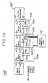
- a second embodiment of the present invention will be discussed with reference to Figs. 10 and 11.
- the second embodiment corresponds to the second known adder shown in Fig. 5 and 6.
- a binary adder 100′ shown in Fig. 10 differs from the counterpart 100 of Fig. 8 in that the former arrangement is provided with a block carry-in generator 92′ externally of BCLA units 0 to 3.
- the binary adder 100′ further includes a one-bit generator 200′ in addition to the four BCLA units 0 to 3.
- the generator 200′ operates in exactly the same manner as the generator 200 disclosed in connection with Fig. 8, so that a further description is considered unnecessary.
- each of the BCLA units 1, 2 and 3 is provided with two kinds of output terminals G and P from which the carry generate and carry propagate variables G(n) and P(n) are derived (n assumes 1, 2 or 3).
- these variables G(n) and P(n) are applied to the block carry-in generator 92′ in the second embodiment.
- the generator 92′ applies the output thereof (viz., a carry-in) to a terminal Cd′ of each of the BCLA units 0 to 3.
- the reference letters Ci and Co, which are used in the first embodiment, are also used for the same purposes.
- Fig. 11 illustrates in block diagram form, one of the BCLA units shown in Fig. 10.
- the BCLA units 0, 1, 2 and 3 each has the same circuit configuration. Since the arrangement of Fig. 11 has essentially the same configuration as that of Fig. 9, like elements are denoted by like reference numerals.
- the circuit arrangement of Fig. 11 differs from that of Fig. 8 in that (a) the output of each of the variable detectors 42, 44 of the former arrangement is not split and hence only two buffers 46′ and 48′ are provided; and (b) the former arrangement is not provided with any block carry-in generator. Other than this, the remaining portions of Figs. 11 and 9 are identical. Since the Fig. 11 arrangement operates in exactly the same manner as the Fig. 9 arrangement further description regarding the operation thereof is considered unnecessary.
Landscapes
- Engineering & Computer Science (AREA)
- Physics & Mathematics (AREA)
- General Physics & Mathematics (AREA)
- Theoretical Computer Science (AREA)
- Pure & Applied Mathematics (AREA)
- Mathematical Analysis (AREA)
- Computational Mathematics (AREA)
- Computing Systems (AREA)
- Mathematical Optimization (AREA)
- General Engineering & Computer Science (AREA)
- Detection And Correction Of Errors (AREA)
- Advance Control (AREA)
- Error Detection And Correction (AREA)
- Complex Calculations (AREA)
Applications Claiming Priority (2)
| Application Number | Priority Date | Filing Date | Title |
|---|---|---|---|
| JP1142226A JP2621480B2 (ja) | 1989-06-06 | 1989-06-06 | 加算回路検査装置 |
| JP142226/89 | 1989-06-06 |
Publications (3)
| Publication Number | Publication Date |
|---|---|
| EP0401783A2 true EP0401783A2 (fr) | 1990-12-12 |
| EP0401783A3 EP0401783A3 (fr) | 1991-10-30 |
| EP0401783B1 EP0401783B1 (fr) | 1998-03-18 |
Family
ID=15310349
Family Applications (1)
| Application Number | Title | Priority Date | Filing Date |
|---|---|---|---|
| EP19900110694 Expired - Lifetime EP0401783B1 (fr) | 1989-06-06 | 1990-06-06 | Dispositif numérique de contrÔle d'erreur dans un additionneur binaire comportant des unités à retenue de bloc anticipée |
Country Status (4)
| Country | Link |
|---|---|
| EP (1) | EP0401783B1 (fr) |
| JP (1) | JP2621480B2 (fr) |
| CA (1) | CA2018271C (fr) |
| DE (1) | DE69032142T2 (fr) |
Family Cites Families (6)
| Publication number | Priority date | Publication date | Assignee | Title |
|---|---|---|---|---|
| DE1524141A1 (de) * | 1965-04-05 | 1970-07-09 | Ibm | Schaltungsanordnung zur schnellen Parallel-Addition binaerer Operanden |
| US3470366A (en) * | 1967-01-13 | 1969-09-30 | Ibm | Fast flush adder |
| US3925647A (en) * | 1974-09-30 | 1975-12-09 | Honeywell Inf Systems | Parity predicting and checking logic for carry look-ahead binary adder |
| US4084253A (en) * | 1977-01-03 | 1978-04-11 | Honeywell Information Systems Inc. | Current mode arithmetic logic circuit with parity prediction and checking |
| US4081860A (en) * | 1977-01-03 | 1978-03-28 | Honeywell Information Systems Inc. | Current mode 4-bit arithmetic logic unit with parity |
| JPS55946A (en) * | 1978-06-19 | 1980-01-07 | Fujitsu Ltd | Adder with parity generating circuit part for binary-decimal addition result |
-
1989
- 1989-06-06 JP JP1142226A patent/JP2621480B2/ja not_active Expired - Lifetime
-
1990
- 1990-06-05 CA CA 2018271 patent/CA2018271C/fr not_active Expired - Fee Related
- 1990-06-06 EP EP19900110694 patent/EP0401783B1/fr not_active Expired - Lifetime
- 1990-06-06 DE DE1990632142 patent/DE69032142T2/de not_active Expired - Fee Related
Also Published As
| Publication number | Publication date |
|---|---|
| CA2018271C (fr) | 1997-09-30 |
| EP0401783B1 (fr) | 1998-03-18 |
| JPH038019A (ja) | 1991-01-16 |
| JP2621480B2 (ja) | 1997-06-18 |
| CA2018271A1 (fr) | 1990-12-06 |
| DE69032142D1 (de) | 1998-04-23 |
| EP0401783A3 (fr) | 1991-10-30 |
| DE69032142T2 (de) | 1998-10-08 |
Similar Documents
| Publication | Publication Date | Title |
|---|---|---|
| US5253195A (en) | High speed multiplier | |
| EP0113391B1 (fr) | Multiplicateur numérique et méthode d'addition des produits partiels dans un multiplicateur numérique | |
| US3925647A (en) | Parity predicting and checking logic for carry look-ahead binary adder | |
| Sparmann et al. | On the effectiveness of residue code checking for parallel two's complement multipliers | |
| Davis | The ILLIAC IV processing element | |
| US5081629A (en) | Fault isolation for multiphase clock signals supplied to dual modules which are checked by comparison using residue code generators | |
| US3938087A (en) | High speed binary comparator | |
| US4224680A (en) | Parity prediction circuit for adder/counter | |
| US5010511A (en) | Digit-serial linear combining apparatus useful in dividers | |
| US4924467A (en) | System for checking duplicate logic using complementary residue codes to achieve high error coverage with a minimum of interface signals | |
| US7170317B2 (en) | Sum bit generation circuit | |
| Kumar et al. | On-line detection of faults in carry-select adders | |
| JPH10505929A (ja) | デジタル演算回路 | |
| JP2554452B2 (ja) | 自己検査型補数加算器ユニット | |
| EP0401783A2 (fr) | Dispositif numérique de contrôle d'erreur dans un additionneur binaire comportant des unités à retenue de bloc anticipée | |
| US5126965A (en) | Conditional-sum carry structure compiler | |
| EP0723342A2 (fr) | Appareil de correction d'erreurs | |
| Nicolaidis et al. | Design of fault-secure parity-prediction booth multipliers | |
| US6484193B1 (en) | Fully pipelined parallel multiplier with a fast clock cycle | |
| US4924423A (en) | High speed parity prediction for binary adders using irregular grouping scheme | |
| EP0534760A2 (fr) | Dispositif de multiplication à grande vitesse | |
| US7386583B2 (en) | Carry generator based on XOR, and conditional select adder using the carry generator, and method therefor | |
| US6631393B1 (en) | Method and apparatus for speculative addition using a limited carry | |
| US4958353A (en) | Device for calculating the parity bits of a sum of two numbers | |
| KR100241071B1 (ko) | 합과 합+1을 병렬로 생성하는 가산기 |
Legal Events
| Date | Code | Title | Description |
|---|---|---|---|
| PUAI | Public reference made under article 153(3) epc to a published international application that has entered the european phase |
Free format text: ORIGINAL CODE: 0009012 |
|
| 17P | Request for examination filed |
Effective date: 19900704 |
|
| AK | Designated contracting states |
Kind code of ref document: A2 Designated state(s): DE FR NL |
|
| PUAL | Search report despatched |
Free format text: ORIGINAL CODE: 0009013 |
|
| AK | Designated contracting states |
Kind code of ref document: A3 Designated state(s): DE FR NL |
|
| 17Q | First examination report despatched |
Effective date: 19950222 |
|
| GRAG | Despatch of communication of intention to grant |
Free format text: ORIGINAL CODE: EPIDOS AGRA |
|
| GRAG | Despatch of communication of intention to grant |
Free format text: ORIGINAL CODE: EPIDOS AGRA |
|
| GRAG | Despatch of communication of intention to grant |
Free format text: ORIGINAL CODE: EPIDOS AGRA |
|
| GRAH | Despatch of communication of intention to grant a patent |
Free format text: ORIGINAL CODE: EPIDOS IGRA |
|
| GRAH | Despatch of communication of intention to grant a patent |
Free format text: ORIGINAL CODE: EPIDOS IGRA |
|
| GRAA | (expected) grant |
Free format text: ORIGINAL CODE: 0009210 |
|
| AK | Designated contracting states |
Kind code of ref document: B1 Designated state(s): DE FR NL |
|
| REF | Corresponds to: |
Ref document number: 69032142 Country of ref document: DE Date of ref document: 19980423 |
|
| ET | Fr: translation filed | ||
| PLBE | No opposition filed within time limit |
Free format text: ORIGINAL CODE: 0009261 |
|
| STAA | Information on the status of an ep patent application or granted ep patent |
Free format text: STATUS: NO OPPOSITION FILED WITHIN TIME LIMIT |
|
| 26N | No opposition filed | ||
| PGFP | Annual fee paid to national office [announced via postgrant information from national office to epo] |
Ref country code: DE Payment date: 19990607 Year of fee payment: 10 |
|
| PGFP | Annual fee paid to national office [announced via postgrant information from national office to epo] |
Ref country code: FR Payment date: 19990610 Year of fee payment: 10 |
|
| PGFP | Annual fee paid to national office [announced via postgrant information from national office to epo] |
Ref country code: NL Payment date: 19990628 Year of fee payment: 10 |
|
| PG25 | Lapsed in a contracting state [announced via postgrant information from national office to epo] |
Ref country code: NL Free format text: LAPSE BECAUSE OF NON-PAYMENT OF DUE FEES Effective date: 20010101 |
|
| PG25 | Lapsed in a contracting state [announced via postgrant information from national office to epo] |
Ref country code: FR Free format text: LAPSE BECAUSE OF NON-PAYMENT OF DUE FEES Effective date: 20010228 |
|
| NLV4 | Nl: lapsed or anulled due to non-payment of the annual fee |
Effective date: 20010101 |
|
| REG | Reference to a national code |
Ref country code: FR Ref legal event code: ST |
|
| PG25 | Lapsed in a contracting state [announced via postgrant information from national office to epo] |
Ref country code: DE Free format text: LAPSE BECAUSE OF NON-PAYMENT OF DUE FEES Effective date: 20010403 |