EP0401807B1 - Mécanisme de transmission - Google Patents
Mécanisme de transmission Download PDFInfo
- Publication number
- EP0401807B1 EP0401807B1 EP90110740A EP90110740A EP0401807B1 EP 0401807 B1 EP0401807 B1 EP 0401807B1 EP 90110740 A EP90110740 A EP 90110740A EP 90110740 A EP90110740 A EP 90110740A EP 0401807 B1 EP0401807 B1 EP 0401807B1
- Authority
- EP
- European Patent Office
- Prior art keywords
- rotary member
- rotary
- clutch spring
- clutch
- spring
- Prior art date
- Legal status (The legal status is an assumption and is not a legal conclusion. Google has not performed a legal analysis and makes no representation as to the accuracy of the status listed.)
- Expired - Lifetime
Links
- 230000002093 peripheral effect Effects 0.000 claims description 16
- 230000001050 lubricating effect Effects 0.000 claims description 4
- 230000001360 synchronised effect Effects 0.000 claims description 2
- 239000000314 lubricant Substances 0.000 description 23
- 239000000463 material Substances 0.000 description 6
- 230000005540 biological transmission Effects 0.000 description 3
- 238000010276 construction Methods 0.000 description 3
- 230000003247 decreasing effect Effects 0.000 description 3
- 230000000717 retained effect Effects 0.000 description 3
- 238000000034 method Methods 0.000 description 2
- 230000002159 abnormal effect Effects 0.000 description 1
- 230000015572 biosynthetic process Effects 0.000 description 1
- 238000007796 conventional method Methods 0.000 description 1
- 238000011161 development Methods 0.000 description 1
- 230000018109 developmental process Effects 0.000 description 1
- 230000000694 effects Effects 0.000 description 1
- 238000005461 lubrication Methods 0.000 description 1
- 238000004519 manufacturing process Methods 0.000 description 1
- 238000000465 moulding Methods 0.000 description 1
- 239000011148 porous material Substances 0.000 description 1
- 238000005245 sintering Methods 0.000 description 1
Images




Classifications
-
- F—MECHANICAL ENGINEERING; LIGHTING; HEATING; WEAPONS; BLASTING
- F16—ENGINEERING ELEMENTS AND UNITS; GENERAL MEASURES FOR PRODUCING AND MAINTAINING EFFECTIVE FUNCTIONING OF MACHINES OR INSTALLATIONS; THERMAL INSULATION IN GENERAL
- F16D—COUPLINGS FOR TRANSMITTING ROTATION; CLUTCHES; BRAKES
- F16D13/00—Friction clutches
- F16D13/08—Friction clutches with a helical band or equivalent member, which may be built up from linked parts, with more than one turn embracing a drum or the like, with or without an additional clutch actuating the end of the band
-
- B—PERFORMING OPERATIONS; TRANSPORTING
- B65—CONVEYING; PACKING; STORING; HANDLING THIN OR FILAMENTARY MATERIAL
- B65H—HANDLING THIN OR FILAMENTARY MATERIAL, e.g. SHEETS, WEBS, CABLES
- B65H3/00—Separating articles from piles
- B65H3/02—Separating articles from piles using friction forces between articles and separator
- B65H3/06—Rollers or like rotary separators
- B65H3/0669—Driving devices therefor
-
- F—MECHANICAL ENGINEERING; LIGHTING; HEATING; WEAPONS; BLASTING
- F16—ENGINEERING ELEMENTS AND UNITS; GENERAL MEASURES FOR PRODUCING AND MAINTAINING EFFECTIVE FUNCTIONING OF MACHINES OR INSTALLATIONS; THERMAL INSULATION IN GENERAL
- F16D—COUPLINGS FOR TRANSMITTING ROTATION; CLUTCHES; BRAKES
- F16D13/00—Friction clutches
- F16D13/02—Friction clutches disengaged by the contact of a part mounted on the clutch with a stationarily-mounted member
- F16D13/025—Friction clutches disengaged by the contact of a part mounted on the clutch with a stationarily-mounted member with a helical band or equivalent member with two or more turns embracing a drum or the like
Definitions
- the present invention relates to a rotary driving force transmitting apparatus using a spring clutch adapted to be used with a sheet feeding system and the like.
- spring clutches have simple constructions and are inexpensive, they have been used as driving force transmitting apparatuses with various systems in various technical fields.
- a spring clutch has been used for permitting and prohibiting the transmission of a driving force from a motor to a supply roller for supplying or feeding out sheets one by one from a cassette in which a plurality of sheets are stacked.
- a sheet material S fed by a supply roller 50a is guided by guide plates 52a and 52b disposed at a downstream side with respect to a sheet feeding direction (referred to as merely "downstream side” hereinafter) until it reaches temporarily stopped regist rollers 53, where the skew-feed of the sheet is corrected by abutting a leading end of the sheet against the regist rollers. Then, by rotating the regist rollers, the sheet S is fed to a recording portion of the printer.
- a spring clutch is attached to one end of a rotary shaft 51 of the supply roller 50a.
- An input gear 54 is freely rotatably mounted near the end of the rotary shaft 51, which gear is meshed with and rotated by a gear connected to a driving motor (not shown).
- a cylindrical output boss 55 acting as a driving force transmitting member is inserted on and fixed to the end of the rotary shaft 51.
- the gear 54 and the output boss 55 have cylindrical portions 54a and 55a, respectively, which have substantially the same diameters and are disposed adjacent to each other.
- a clutch spring 56 is fitted on outer circumferential surfaces of the cylindrical portions 54a, 55a.
- a control cylinder 57 having a notch 57a formed therein is arranged around the clutch spring 56 and is press-fitted onto the cylindrical portions (54a, 55a).
- the control cylinder 57 has an integral projection 57b formed thereon, against which an actuator 58 driven by a solenoid (not shown) can be engaged or disengaged.
- One end 56a of the clutch spring 56 is cocked in upright relation with the cylindrical portion 54a to engage by the notch 57a of the control cylinder 57, and the other end 56b of the spring is fitted into a recess 55c formed in a flange portion 55b having a larger diameter than that of the cylindrical portion 55a of the output boss 55.
- the clutch spring 56 is tightened against the cylindrical portions 54a, 55a by a tightening force thereof and a friction force between the spring and the input gear 54, whereby the clutch spring 56, output boss 55 and rotary shaft 51 are rotated altogether.
- the supply roller 50a fixed to the rotary shaft 51 is also rotated to feed the sheet material S.
- many of the used clutch springs comprise coils having rectangular cross-sections wound spirally in order to provide a transmission torque.
- the edge of the rectangular coil or coils scrape or sweep the surface of the cylindrical portion 54a, if the lubricant 59 remains between the clutch spring 56 and the cylindrical portion 54a, it will be swept from the surface of the cylindrical portion 54a to worsen the lubrication feature between the clutch spring and the cylindrical portion.
- the cylindrical portion 54a is made of porous material to keep the lubricant into the minute holes on the cylindrical portion, since the cylindrical portion 54a has a rough surface, the contact area between the clutch spring 56 and the cylindrical portion 54a is decreased, with the result that the adequate transmission torque cannot be obtained.
- the lubricant 59 could not adequately supplied to the sliding surface of the cylindrical portion 54a on which the clutch spring 56 was slidably moved.
- a rotary driving force transmitting apparatus of the kind defined by the precharacterizing features of claim 1 is known from the US-A-2,669,331.
- the lubricating grooves of this apparatus run in parallel to the rotary axis of the first rotary member as particularly shown in Fig. 5 of this document. Therefore, the lubricant can escape from the sliding surfaces of the spring clutch, thereby diminuishing the lubricating effect.
- the JP-A-58211023 discloses a coil spring having a reserving groove in the inner peripheral surface of the coil. Consequently, this coil spring is intended to be used in connection only with smooth rotary members.
- An object of the present invention is to provide a rotary driving force transmitting apparatus which can solve the afore-mentioned conventional problems and can rapidly supply lubricant to its sliding surfaces.
- Fig. 1 is a perspective view of a driving force transmitting mechanism
- Fig. 2 is partial sectional views of the driving force transmitting mechanism
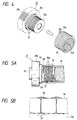
- Figs. 3 to 5 are views showing parts of the driving force transmitting mechanism
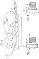
- Fig. 6 is a diagrammatic elevational view of a laser beam printer incorporating the driving force transmitting mechanism therein.
- the reference numeral 1 denotes a scanner unit for illuminating a laser beam in response to an image signal; and 2 denotes a process cartridge incorporating therein an image forming means such as a photosensitive drum 3 acting as an image bearing member, a first charger 4 comprising a corona charger, a developing device 5 containing toner, a cleaner 6 and the like.
- the laser beam emitted from the scanner unit 1 is illuminated onto the photosensitive drum 3 previously charged by the first charger 4 in the process cartridge 2 through a mirror 7 to form a latent image.
- the latent image is then visualized by forming a toner image by means of the developing device 5.
- the sheet material S fed from a cassette 8 by a supply roller 9 is guided by an upper guide plate 10a and a lower guide plate 10b to reach regist rollers 11, where the skew-feed of the sheet is corrected. Then, the sheet is intermittently fed by the regist rollers 11 to a transfer and recording portion of the laser beam printer in synchronous with a leading end of the toner image formed on the photosensitive drum 3.
- the reference numeral 12 denotes a transfer charger for transferring the toner image formed on the photosensitive drum 3 onto the sheet material S.
- the sheet material S is fed to a fixing device 14 by means of feeding rollers 13. Further, after the transferred image has been permanently fixed on the sheet material S, the latter is ejected onto a tray 16a or tray 16b through a respective feeding path selected by a flapper 15.
- a rotary shaft 19 is disposed, which shaft extends transversely to the width of the sheet and is rotatably supported by a side frame 17 of the apparatus through a bearing 18 in a cantilever fashion.
- the supply roller 9 of semi-circular cross-section having a downwardly directed D-shaped or semi-circular surface is fixedly mounted on the rotary shaft 19.
- idle rollers 20a and 20b which can be engaged by an uppermost sheet S on the sheet stack contained in the cassette 8 are freely rotatably mounted on the shaft 19.
- the idle rollers 20a and 20b is abutted against the uppermost sheet S when the apparatus is in a waiting condition.
- a slidable cylinder 21a, and an input gear (input driving force transmitting member) 21 on which a gear 21b having a larger diameter than that of the slidable cylinder 21a are freely rotatably mounted on the rotary shaft 19.
- the input gear 21 is meshed with and driven by a gear 22 driven by a motor (not shown) arranged in the vicinity of the gear 21a.
- an output boss (output driving force transmitting member) 23 having a slidable cylinder 23a of substantially the same diameter as that of the input gear 21 and having an integral flange portion 23b of a larger diameter than that of the slidable cylinder 23a is fixedly mounted.
- the slidable cylinders 21a and 23a are arranged on the rotary shaft 19 in an abutment relation with each other.
- a clutch spring 24 is mounted on the outer peripheral surfaces of the opposed slidable cylinders 21a and 23a of the input gear 21 and the output boss 23, a clutch spring 24 is mounted.
- a control sleeve (control member) 25 is disposed around the clutch spring 24 with an adequate clearance between the spring and the sleeve and is rotatably mounted between the gear 21b and the flange portion 23b.
- the clutch spring 24 is press-fitted onto the opposed slidable cylinders 21a and 23a of the input gear 21 and the output boss 23, and an end 24a of the spring near the slidable cylinder 21a is cocked in an upright relation with respect to the slidable cylinder 21a to enter into a notch 25a formed in the control sleeve 25. Further, the other end 24b of the clutch spring 24 near the slidable cylinder 23a is fitted into a recess 23c formed in the flange portion 23b. A projection 25b is integrally formed on the outer peripheral surface of the control sleeve 25.
- An actuator 26 driven by a solenoid (not shown) is arranged in opposed relation to the projection 25b to engage by or disengage from the latter.
- the actuator 26 is engaged by the projection when the solenoid is disenergized, and when the solenoid is energized it attracts the actuator 26 to disengage the latter from the projection 25b.
- a spiral groove 27 is formed for filling or containing lubricant such as oil.
- a shoulder 21c is provided between the slidable cylinder 21a and the gear 21b, there is provided a shoulder 21c on which an end portion of the control sleeve 25 is slidably fitted.
- the input gear 21 is being rotated by the gear 22 meshed with the gear 21 and driven by the motor (not shown), and, thus, the clutch spring 24 and the control sleeve 25 engaged by the spring at its one end tend to rotate.
- the actuator 26 is engaged by the projection 25b, the control sleeve 25 cannot be rotated.
- the end 24a of the clutch spring 24 is engaged by the notch 25a of the control sleeve 25, the rotational force causes the inner diameter of the clutch spring 24 to increase, thus decreasing the fastening force of the spring acting against the slidable cylinder 21a.
- the groove 27 is formed spirally, it is possible to quickly form a film of the lubricant 28 on the sliding surfaces between the slidable cylinder 21a and the clutch spring 24 in consequence of the free rotation of the input gear 21.
- the spiral configuration in order to prevent the clutch spring 24 from entering into the groove 27 and to improve the lubricant ability, as shown in Fig. 5B showing a portion of Fig. 5A in an enlarged scale, it was found that the effective result could be obtained when each coil of the clutch spring stranded two or three spiral grooves, and, in effect, the spiral grooves had a pitch of 200 ⁇ to 300 ⁇ .
- a portion which must be lubricated is an area near a distal end 21d of the slidable cylinder 21a, if the spiral groove 27 is formed to direct the lubricant 28 from the shoulder 21c to the distal end 21d, it will be possible to facilitate the supply of the lubricant 28 to the sliding surface between the clutch spring 24 and the slidable cylinder 21a and to supply the lubricant thereto for a long time.
- the solenoid (not shown) is energized to attract the actuator 26, thereby disengaging the latter from the projection 25b.
- the clutch spring 24 is tightened against the slidable cylinders 21a and 23a by the tightening force of the spring itself and the friction force between the spring and the input gear 21. In this way, the clutch spring 24, output boss 23 and rotary shaft 19 are rotated altogether, whereby the supply roller 9 can feed the sheet S one by one.
- the lubricant 28 forming the lubricant film on the slidable cylinder 21a is quickly returned to the groove 27 and to the spaces formed between the coils of the clutch spring 24.
- a plurality grooves 34 may be formed on the peripheral surface of a slidable cylinder 33a of an input gear 33 in parallel with the rotary shaft 19. As shown in Fig. 9B, the grooves are disposed around the circumference of the slidable cylinder 33a at a predetermined angular pitch.
- grooves can be obtained by an moulding operation, the productivity is further improved.
- ridged edges of the grooves should be eliminated by the barrel finishing and the like in order to facilitate the formation of the lubricant film and to minimize the variation of the sliding torque.
- annular grooves 32 are formed in the peripheral surface of a slidable cylinder 31a of an input gear 31 by the knurling.
- the lubricant can be quickly supplied from the grooves to the peripheral surface of the slidable cylinder on which the clutch spring slides at the non-connection condition of the clutch.
- a spring clutch which can prevent the seizure, scratch and/or abnormal wear on the sliding surface on which the clutch spring slides, and which has high stability and reliability.
- the lubricant film can be quickly formed on the peripheral surface of the slidable cylinder at the non-connection condition of the clutch, it is possible to prevent the stick slip of the clutch spring to eliminate the noise, and at the same time to reduce the sliding torque of the clutch.
- the time required for the engagement and disengagement of the clutch (the timing of the half-clutch condition) can be reduced. Accordingly, it is possible to provide a spring clutch having quick response.
- the spring clutch can be applied to the case where the clutch is subjected to a larger load.
Landscapes
- Engineering & Computer Science (AREA)
- General Engineering & Computer Science (AREA)
- Mechanical Engineering (AREA)
- Physics & Mathematics (AREA)
- Electromagnetism (AREA)
- Mechanical Operated Clutches (AREA)
- Paper Feeding For Electrophotography (AREA)
- Exposure Or Original Feeding In Electrophotography (AREA)
- Transmission Devices (AREA)
Claims (7)
- Appareil de transmission d'une force d'entraînement en rotation comportant :- un premier élément tournant (31a), qui est l'élément menant, ayant une forme cylindrique et des gorges (32) de lubrification formées dans sa surface périphérique extérieure,- un second élément tournant (23a), qui est l'élément mené, ayant une forme cylindrique et une surface périphérique extérieure sensiblement du même diamètre que celle du premier élément tournant, et- un ressort hélicoïdal (24) enroulé autour des surfaces périphériques extérieures des premier et second éléments tournants, engagé avec le second élément tournant afin d'être tourné par rapport à lui et engagé avec le premier élément tournant lorsque la force de rotation est transmise,caractérisé en ce que
les gorges (32) de lubrification sont prévues sous une forme annulaire et sont disposées parallèlement entre elles. - Appareil selon la revendication 1, dans lequel
le premier élément tournant comporte une roue dentée (21b) qui est en rotation d'un seul bloc avec le premier élément. - Appareil selon l'une quelconque des revendications précédentes, dans lequel
le second élément tournant comporte une partie d'engagement (23c) engagée par une extrémité (24b) du ressort hélicoïdal. - Appareil selon l'une quelconque des revendications précédentes, comprenant en outre une force d'entraînement pour faire tourner le premier élément tournant.
- Appareil selon l'une quelconque des revendications précédentes, dans lequel
le ressort hélicoïdal est enroulé dans un sens tel qu'il est serré contre les premier et second éléments tournants lorsque le premier élément tournant est en rotation. - Appareil selon l'une quelconque des revendications précédentes, comportant en outre- un élément de commande (25b) destiné à bloquer sélectivement une extrémité (24a) du ressort hélicoïdal à proximité du premier élément tournant, de façon à commander le serrage du ressort hélicoïdal contre les premier et second éléments tournants.
- Utilisation d'un appareil selon l'une quelconque des revendications précédentes, dans un système de formation d'images comportant- un troisième élément tournant (9) qui est tourné en synchronisme avec le deuxième élément tournant pour appliquer une force de rotation à une feuille S, et- des moyens (2) de formation d'images destinés à former une image sur la feuille avancée par le troisième élément tournant.
Applications Claiming Priority (2)
| Application Number | Priority Date | Filing Date | Title |
|---|---|---|---|
| JP1144244A JP2607956B2 (ja) | 1989-06-08 | 1989-06-08 | 駆動力伝達機構 |
| JP144244/89 | 1989-06-08 |
Publications (3)
| Publication Number | Publication Date |
|---|---|
| EP0401807A2 EP0401807A2 (fr) | 1990-12-12 |
| EP0401807A3 EP0401807A3 (fr) | 1991-10-23 |
| EP0401807B1 true EP0401807B1 (fr) | 1996-11-13 |
Family
ID=15357595
Family Applications (1)
| Application Number | Title | Priority Date | Filing Date |
|---|---|---|---|
| EP90110740A Expired - Lifetime EP0401807B1 (fr) | 1989-06-08 | 1990-06-06 | Mécanisme de transmission |
Country Status (4)
| Country | Link |
|---|---|
| US (1) | US5435539A (fr) |
| EP (1) | EP0401807B1 (fr) |
| JP (1) | JP2607956B2 (fr) |
| DE (1) | DE69029101T2 (fr) |
Families Citing this family (36)
| Publication number | Priority date | Publication date | Assignee | Title |
|---|---|---|---|---|
| JPH0750739A (ja) * | 1993-06-15 | 1995-02-21 | Gold Star Co Ltd | ファクシミリの多枚給紙装置 |
| US5462373A (en) * | 1994-05-03 | 1995-10-31 | Hewlett-Packard Company | Sheet advancement system with phase-adjustable roller arrangement |
| GB9421812D0 (en) * | 1994-10-29 | 1994-12-14 | Kodak Ltd | Processing apparatus |
| JP3272910B2 (ja) * | 1995-06-16 | 2002-04-08 | シャープ株式会社 | スプリングクラッチ機構および給紙装置のクラッチ機構 |
| KR0172031B1 (ko) * | 1995-10-13 | 1999-03-30 | 김광호 | 반도체장치의 층간 절연막 형성방법 |
| WO1998004383A1 (fr) * | 1996-07-29 | 1998-02-05 | Matsushita Electric Industrial Co., Ltd. | Machine-outil |
| US5956930A (en) * | 1996-12-04 | 1999-09-28 | Privatizer Systems, Inc. | Apparatus and method of forming an envelope in a document security apparatus |
| US5996317A (en) * | 1996-12-04 | 1999-12-07 | Privatizer Systems, Inc. | Method for providing confidentiality to a facsimile transmission having a non-printed back enclosure sheet |
| US5937619A (en) * | 1996-12-04 | 1999-08-17 | Privatizer Systems Incorporated | Apparatus and method for sealing an envelope having a first lateral side and a second lateral side in a document security apparatus |
| US6076336A (en) * | 1996-12-04 | 2000-06-20 | Privatizer Systems, Inc. | Apparatus and method for advancing a confidential sheet into a pocket defined by a number of enclosure sheets |
| US5941048A (en) * | 1996-12-04 | 1999-08-24 | Privatizer Systems, Inc | Apparatus and method of sealing an envelope in a document security apparatus |
| US5887411A (en) * | 1996-12-04 | 1999-03-30 | Privatizer Systems, Inc. | Apparatus and method for positioning a number of non-transparent enclosure sheets in a document security apparatus |
| US5946889A (en) * | 1996-12-04 | 1999-09-07 | Privatizer Systems, Inc | Apparatus and method for enclosing a confidential sheet between a first enclosure sheet and a second enclosure sheet within a document security apparatus |
| US5934045A (en) * | 1996-12-04 | 1999-08-10 | Privatizer Systems, Inc. | Method for providing confidentiality to a facsimile transmission having information associated with a first page of the transmission printed on a first enclosure sheet |
| US5979148A (en) * | 1996-12-04 | 1999-11-09 | Privatizer Systems, Inc. | Apparatus and method for sealing an envelope in a document security apparatus having a sealing roller with a sealing ridge attached thereto |
| US6168147B1 (en) * | 1996-12-27 | 2001-01-02 | Murata Kikai Kabushiki Kaisha | Transmission mechanism for pick-up roller |
| JP3083509B2 (ja) * | 1997-12-08 | 2000-09-04 | 三星電子株式会社 | 自動給紙装置 |
| US6059279A (en) * | 1998-09-14 | 2000-05-09 | Xerox Corporation | Retard sheet separator-feeder with retarded sheets kickback reduction |
| US6805341B2 (en) * | 2002-11-22 | 2004-10-19 | Kabushiki Kaisha Toshiba | Sheet feeding device and image forming apparatus |
| JP3718776B2 (ja) * | 2003-02-12 | 2005-11-24 | インターナショナル・ビジネス・マシーンズ・コーポレーション | 情報処理装置及び回転制御装置 |
| KR100580250B1 (ko) * | 2003-12-13 | 2006-05-16 | 삼성전자주식회사 | 화상형성장치의 픽업장치 |
| TWI280225B (en) * | 2005-09-13 | 2007-05-01 | Benq Corp | A separation roller set of an automatic document feeder (ADF) |
| TW200800633A (en) * | 2006-06-16 | 2008-01-01 | Primax Electronics Ltd | Pick-up apparatus |
| CN100572226C (zh) * | 2006-06-23 | 2009-12-23 | 致伸科技股份有限公司 | 取纸装置 |
| JP5196099B2 (ja) * | 2006-10-04 | 2013-05-15 | 富士ゼロックス株式会社 | スプリングクラッチ装置及び画像形成装置 |
| TWI316471B (en) * | 2006-12-19 | 2009-11-01 | Teco Image Sys Co Ltd | Differential apparatus in paper separation |
| JP2010002578A (ja) * | 2008-06-19 | 2010-01-07 | Kyocera Mita Corp | 軸受構造及びこれを備えたクリーニング装置、画像形成装置 |
| JP2010030768A (ja) * | 2008-07-30 | 2010-02-12 | Seiko Epson Corp | 給送装置及び記録装置 |
| DE102009000545A1 (de) * | 2009-02-02 | 2010-08-05 | Robert Bosch Gmbh | Lastdrehmomentsperre, Aggregat mit Lastdrehmomentsperre sowie Verfahren zum Herstellen einer Lastdrehmomentsperre |
| CN102120532B (zh) * | 2010-01-08 | 2013-07-10 | 致伸科技股份有限公司 | 摩擦轮以及使用该摩擦轮的摩擦轮模块 |
| CN102311005B (zh) * | 2010-07-02 | 2014-04-09 | 致伸科技股份有限公司 | 自动馈纸装置的取纸模块 |
| JP5003804B2 (ja) * | 2010-08-17 | 2012-08-15 | コニカミノルタビジネステクノロジーズ株式会社 | 回転伝達機構及び給紙装置 |
| TWI403452B (zh) * | 2010-10-22 | 2013-08-01 | Teco Image Sys Co Ltd | 饋紙裝置之取紙結構 |
| MX2013007900A (es) * | 2011-01-06 | 2014-02-20 | Hunter Douglas Ind Bv | Accionamiento para eje de carrete para operar un recubrimiento arquitectonico y modulo de frenado de eje para usar con el mismo. |
| ITTO20111019A1 (it) * | 2011-11-07 | 2013-05-08 | Dayco Europe Srl | Gruppo puleggia per pompa acqua perfezionato |
| TWI465345B (zh) * | 2011-12-02 | 2014-12-21 | Primax Electronics Ltd | 自動饋紙裝置 |
Citations (4)
| Publication number | Priority date | Publication date | Assignee | Title |
|---|---|---|---|---|
| US2669331A (en) * | 1950-04-20 | 1954-02-16 | Ncr Co | Motor clutch |
| JPS57200732A (en) * | 1981-06-03 | 1982-12-09 | Nippon Denso Co Ltd | Electromagnetic spring clutch |
| JPS58211023A (ja) * | 1982-05-31 | 1983-12-08 | Matsushita Electric Ind Co Ltd | スプリングクラツチ |
| JPS6098223A (ja) * | 1983-10-31 | 1985-06-01 | Toshiba Corp | スプリングクラツチ |
Family Cites Families (9)
| Publication number | Priority date | Publication date | Assignee | Title |
|---|---|---|---|---|
| CA478084A (fr) * | 1951-10-30 | Carleton Starkey William | Methode de fabrication de dispositifs d'embrayages a ressorts | |
| US3128864A (en) * | 1964-04-14 | Torque limiting coil or spring clutch mechanisms | ||
| US1847867A (en) * | 1930-09-29 | 1932-03-01 | Adiel Y Dodge | One-way reactance device |
| US2615543A (en) * | 1948-03-08 | 1952-10-28 | United Shoe Machinery Corp | Spring type clutch |
| US3729077A (en) * | 1970-05-18 | 1973-04-24 | A Torigai | Spring clutch |
| US4280606A (en) * | 1979-05-08 | 1981-07-28 | Pennwalt Corporation | Torque limiting device |
| US4306713A (en) * | 1980-04-25 | 1981-12-22 | International Business Machines Corporation | Document feeder |
| JP2521303B2 (ja) * | 1987-09-07 | 1996-08-07 | シャープ株式会社 | 自動給紙装置 |
| JPH01156241A (ja) * | 1987-12-10 | 1989-06-19 | Matsushita Electric Ind Co Ltd | 給紙装置 |
-
1989
- 1989-06-08 JP JP1144244A patent/JP2607956B2/ja not_active Expired - Fee Related
-
1990
- 1990-06-06 DE DE69029101T patent/DE69029101T2/de not_active Expired - Fee Related
- 1990-06-06 EP EP90110740A patent/EP0401807B1/fr not_active Expired - Lifetime
-
1993
- 1993-02-17 US US08/022,600 patent/US5435539A/en not_active Expired - Lifetime
Patent Citations (4)
| Publication number | Priority date | Publication date | Assignee | Title |
|---|---|---|---|---|
| US2669331A (en) * | 1950-04-20 | 1954-02-16 | Ncr Co | Motor clutch |
| JPS57200732A (en) * | 1981-06-03 | 1982-12-09 | Nippon Denso Co Ltd | Electromagnetic spring clutch |
| JPS58211023A (ja) * | 1982-05-31 | 1983-12-08 | Matsushita Electric Ind Co Ltd | スプリングクラツチ |
| JPS6098223A (ja) * | 1983-10-31 | 1985-06-01 | Toshiba Corp | スプリングクラツチ |
Also Published As
| Publication number | Publication date |
|---|---|
| US5435539A (en) | 1995-07-25 |
| EP0401807A3 (fr) | 1991-10-23 |
| EP0401807A2 (fr) | 1990-12-12 |
| DE69029101T2 (de) | 1997-05-15 |
| JPH0314915A (ja) | 1991-01-23 |
| DE69029101D1 (de) | 1996-12-19 |
| JP2607956B2 (ja) | 1997-05-07 |
Similar Documents
| Publication | Publication Date | Title |
|---|---|---|
| US5435539A (en) | Driving force transmitting apparatus | |
| EP0832833B1 (fr) | Appareil d'alimentation de feuilles | |
| US6829455B2 (en) | Driving force transmission mechanism, image forming apparatus equipped with such a mechanism, and process unit of such an apparatus | |
| US5863036A (en) | Sheet feeding device and image forming apparatus having the same | |
| US5240242A (en) | Sheet feeding device | |
| US5970294A (en) | Cylindrical structural body for use in an image forming apparatus and method of producing the same | |
| CN108241274B (zh) | 离合器设备、处理盒和成像装置 | |
| US5963769A (en) | Multicolor image forming apparatus | |
| EP0833226A3 (fr) | Unité de traitement et appareil de électrostatographique de formation d'image | |
| JP2022149151A (ja) | 駆動装置、及び、画像形成装置 | |
| JP3598192B2 (ja) | 駆動装置 | |
| US20160033026A1 (en) | Driving force transmission mechanism and image forming apparatus | |
| JPH07225538A (ja) | 過負荷安全装置及び画像形成装置 | |
| US5235381A (en) | Rotation controlling apparatus | |
| JPH0859005A (ja) | 給紙分離装置 | |
| JP4546670B2 (ja) | トルクリミッタ及び画像形成装置の用紙分離機構 | |
| US8437662B2 (en) | Driving force transmitting device and image forming apparatus including the same | |
| US5711405A (en) | Spring clutch mechanism and a clutch mechanism for use in a paper feeding apparatus | |
| US11281147B2 (en) | Driving device and image forming apparatus | |
| US20260042627A1 (en) | Shaft and image forming apparatus | |
| JP3715717B2 (ja) | 駆動伝達装置及びシート材給送装置 | |
| JPH115641A (ja) | 駆動伝達装置および給送装置および画像形成装置 | |
| JPH0893784A (ja) | トルクリミッタ並びにそれを用いた紙送り装置及び事務機器 | |
| JPH0748594Y2 (ja) | 画像形成装置 | |
| JPH0874879A (ja) | トルクリミッタ並びにそれを用いた紙送り装置及び事務機器 |
Legal Events
| Date | Code | Title | Description |
|---|---|---|---|
| PUAI | Public reference made under article 153(3) epc to a published international application that has entered the european phase |
Free format text: ORIGINAL CODE: 0009012 |
|
| AK | Designated contracting states |
Kind code of ref document: A2 Designated state(s): DE FR GB IT |
|
| 17P | Request for examination filed |
Effective date: 19910102 |
|
| PUAL | Search report despatched |
Free format text: ORIGINAL CODE: 0009013 |
|
| AK | Designated contracting states |
Kind code of ref document: A3 Designated state(s): DE FR GB IT |
|
| RHK1 | Main classification (correction) |
Ipc: B65H 3/06 |
|
| 17Q | First examination report despatched |
Effective date: 19931130 |
|
| GRAH | Despatch of communication of intention to grant a patent |
Free format text: ORIGINAL CODE: EPIDOS IGRA |
|
| GRAH | Despatch of communication of intention to grant a patent |
Free format text: ORIGINAL CODE: EPIDOS IGRA |
|
| GRAA | (expected) grant |
Free format text: ORIGINAL CODE: 0009210 |
|
| AK | Designated contracting states |
Kind code of ref document: B1 Designated state(s): DE FR GB IT |
|
| PG25 | Lapsed in a contracting state [announced via postgrant information from national office to epo] |
Ref country code: IT Free format text: LAPSE BECAUSE OF FAILURE TO SUBMIT A TRANSLATION OF THE DESCRIPTION OR TO PAY THE FEE WITHIN THE PRESCRIBED TIME-LIMIT;WARNING: LAPSES OF ITALIAN PATENTS WITH EFFECTIVE DATE BEFORE 2007 MAY HAVE OCCURRED AT ANY TIME BEFORE 2007. THE CORRECT EFFECTIVE DATE MAY BE DIFFERENT FROM THE ONE RECORDED. Effective date: 19961113 Ref country code: FR Effective date: 19961113 |
|
| REF | Corresponds to: |
Ref document number: 69029101 Country of ref document: DE Date of ref document: 19961219 |
|
| EN | Fr: translation not filed | ||
| PG25 | Lapsed in a contracting state [announced via postgrant information from national office to epo] |
Ref country code: GB Free format text: LAPSE BECAUSE OF NON-PAYMENT OF DUE FEES Effective date: 19970606 |
|
| PLBE | No opposition filed within time limit |
Free format text: ORIGINAL CODE: 0009261 |
|
| STAA | Information on the status of an ep patent application or granted ep patent |
Free format text: STATUS: NO OPPOSITION FILED WITHIN TIME LIMIT |
|
| 26N | No opposition filed | ||
| GBPC | Gb: european patent ceased through non-payment of renewal fee |
Effective date: 19970606 |
|
| PGFP | Annual fee paid to national office [announced via postgrant information from national office to epo] |
Ref country code: DE Payment date: 20080630 Year of fee payment: 19 |
|
| PG25 | Lapsed in a contracting state [announced via postgrant information from national office to epo] |
Ref country code: DE Free format text: LAPSE BECAUSE OF NON-PAYMENT OF DUE FEES Effective date: 20100101 |