EP0401872B1 - Dispositif de changement de moule pour une machine d'injection de matière plastique - Google Patents
Dispositif de changement de moule pour une machine d'injection de matière plastique Download PDFInfo
- Publication number
- EP0401872B1 EP0401872B1 EP90113480A EP90113480A EP0401872B1 EP 0401872 B1 EP0401872 B1 EP 0401872B1 EP 90113480 A EP90113480 A EP 90113480A EP 90113480 A EP90113480 A EP 90113480A EP 0401872 B1 EP0401872 B1 EP 0401872B1
- Authority
- EP
- European Patent Office
- Prior art keywords
- mould
- guide
- injection
- mold
- changeover
- Prior art date
- Legal status (The legal status is an assumption and is not a legal conclusion. Google has not performed a legal analysis and makes no representation as to the accuracy of the status listed.)
- Expired - Lifetime
Links
- 238000001746 injection moulding Methods 0.000 title claims abstract description 36
- 229920003023 plastic Polymers 0.000 title claims abstract description 11
- 239000004033 plastic Substances 0.000 title claims abstract description 11
- 238000002347 injection Methods 0.000 claims abstract description 60
- 239000007924 injection Substances 0.000 claims abstract description 60
- 230000008878 coupling Effects 0.000 claims description 26
- 238000010168 coupling process Methods 0.000 claims description 26
- 238000005859 coupling reaction Methods 0.000 claims description 26
- 238000006073 displacement reaction Methods 0.000 claims description 15
- 239000000463 material Substances 0.000 claims 2
- 238000005266 casting Methods 0.000 description 5
- 210000000056 organ Anatomy 0.000 description 2
- 101100390736 Danio rerio fign gene Proteins 0.000 description 1
- 101100390738 Mus musculus Fign gene Proteins 0.000 description 1
- 239000000969 carrier Substances 0.000 description 1
- 238000010586 diagram Methods 0.000 description 1
- 238000005516 engineering process Methods 0.000 description 1
- 238000003754 machining Methods 0.000 description 1
- 238000000034 method Methods 0.000 description 1
- 238000007639 printing Methods 0.000 description 1
- 230000000284 resting effect Effects 0.000 description 1
- 239000000243 solution Substances 0.000 description 1
- 239000007921 spray Substances 0.000 description 1
Images





Classifications
-
- B—PERFORMING OPERATIONS; TRANSPORTING
- B29—WORKING OF PLASTICS; WORKING OF SUBSTANCES IN A PLASTIC STATE IN GENERAL
- B29C—SHAPING OR JOINING OF PLASTICS; SHAPING OF MATERIAL IN A PLASTIC STATE, NOT OTHERWISE PROVIDED FOR; AFTER-TREATMENT OF THE SHAPED PRODUCTS, e.g. REPAIRING
- B29C45/00—Injection moulding, i.e. forcing the required volume of moulding material through a nozzle into a closed mould; Apparatus therefor
- B29C45/17—Component parts, details or accessories; Auxiliary operations
- B29C45/176—Exchanging the injection unit or parts thereof
-
- B—PERFORMING OPERATIONS; TRANSPORTING
- B29—WORKING OF PLASTICS; WORKING OF SUBSTANCES IN A PLASTIC STATE IN GENERAL
- B29C—SHAPING OR JOINING OF PLASTICS; SHAPING OF MATERIAL IN A PLASTIC STATE, NOT OTHERWISE PROVIDED FOR; AFTER-TREATMENT OF THE SHAPED PRODUCTS, e.g. REPAIRING
- B29C45/00—Injection moulding, i.e. forcing the required volume of moulding material through a nozzle into a closed mould; Apparatus therefor
- B29C45/17—Component parts, details or accessories; Auxiliary operations
- B29C45/1756—Handling of moulds or mould parts, e.g. mould exchanging means
-
- B—PERFORMING OPERATIONS; TRANSPORTING
- B29—WORKING OF PLASTICS; WORKING OF SUBSTANCES IN A PLASTIC STATE IN GENERAL
- B29C—SHAPING OR JOINING OF PLASTICS; SHAPING OF MATERIAL IN A PLASTIC STATE, NOT OTHERWISE PROVIDED FOR; AFTER-TREATMENT OF THE SHAPED PRODUCTS, e.g. REPAIRING
- B29C45/00—Injection moulding, i.e. forcing the required volume of moulding material through a nozzle into a closed mould; Apparatus therefor
- B29C45/0084—General arrangement or lay-out of plants
Definitions
- the invention relates to a mold changing device according to the preamble of claim 1.
- a transport table can be moved in a linear guide parallel to the spray axis, which is a prerequisite for changing the mold as such, but also for removing the injection mold. It is advantageous that the transport of the injection molds and their transfer from the clamping area to the trolley and vice versa takes place at chest height and horizontally, that is, not 'overhead'.
- the known mold changing devices In order to bridge the distance between the injection mold located in the clamping space of the plastic injection molding machine and the transport table moving parallel to the injection axis, the known mold changing devices use relatively complex mold shifting devices, which also require complex and relatively difficult to control coupling devices, which likewise complicate automation.
- a casting mold shifting device working with an endless chain on a casting mold changing device is also known (DE 32 42 054 C2).
- this mold shifting device is as a separate coupling member a coupling rod is required between the injection mold and shuttle table, the vertical coupling pins of which engage in the body of the injection mold.
- the invention has for its object to develop a mold changing device of the type mentioned in such a way that the mold shifting device of the shuttle table serving as a transport carriage is capable of using the injection mold located in the clamping space between the clamping plates or between the walls of a depot automatically capture an endless chain and pull it onto the transport table in order to push it between the walls of the depot or the clamping plates of the clamping area after a transport movement and release it there from its coupling connection.
- the driver of the transport chain that is ready for coupling can be inserted into the coupling member of an injection mold to be pulled onto the shuttle table, that is to say in the clamping position in the working position, the end of the structural unit comprising the displacement device protruding slightly into the clamping chamber.
- the distance between the coupling members of the injection molds parked in the injection molding machines or in the depot from the plane of symmetry of the guide of the shuttle table and thus the relevant distance of the injection molding machines from the transport trolley can be made particularly small. In this way, the space requirement of the injection molding machine provided with the mold changing device can be minimized. This also applies if several Plastic injection molding machines are operated by a mold changing device.
- the injection mold that is coupled on the shuttle table is usually carried.
- the starting point is moved forward when transporting an injection mold from the shuttle table to its workstation in the injection molding machine or in a depot parking space in such a way that the injection mold arrives in an appropriate position in the injection molding machine or in the depot.
- the shuttle table can travel along one or more injection molding machines without colliding with protruding parts of the injection molding machines when the displacement device is in the rest position.
- the invention is not affected by the fact that it is known per se to use an endless chain in the workpiece carrier changing system of a workpiece machining center for moving workpiece pallets between a stationary pallet receiving table and a linearly movable machining table (special printing "Werner Transfer Center TC 660, TC 800, TC 1000 The new compact concept"). Admittedly, the movement of the chain of the driver in a coupling member of the workpiece pallet also automatically controls or disengages.
- the actual problem of the present invention to pull an injection mold out of the clamping space of an injection molding machine or from the inside of a depot or to push it in there by means of a displacement device, which is located on a transport carriage which can be moved along the injection molding machine and along the depot, is eliminated completely in the known arrangement.
- the mold changing device is described below with reference to the drawing.
- the mold changing device enables a computer-controlled change of the mold on one or more plastic injection molding machines (injection molding machines), which are allocated to a mold storage space-saving, including the transport movements to and from the mold storage.
- the injection molding machine or the injection molding machines each have a cuboid machine base 11.
- the injection molding machine or the injection molding machines are aligned on both sides along the linear guide 45 of the shuttle table 27, which has two rails, in such a way that their rear sides face the guide 45 and their injection axes x-x are parallel to the guide 45 and, in the case of identical injection molding machines, coaxial to one another.
- the mold changing table 27 can have two mold positions, each of which is provided with a mold guide G ′′ and a mold displacement device 20, 21, 26 G ′′, which in turn engages a coupling element (transverse groove 13a) of the injection mold S.
- the mold changing table 27 can be moved on its guide 45 either into a connection position at the mold clamping space F of an injection molding machine or into a connection position at a mold position 44a.
- the vertical plane of symmetry of the mold changing table 27 coincides with the vertical plane of symmetry yy of the guide 45.
- a mold holder is arranged on each half of the symmetry in such a way that its mold guide G ′′ and its mold shifting device (transport chain 20) are mirror-symmetrical to the plane of symmetry yy.
- the changing table 27 is guided by means of a foot plate 27e in the guide 45 formed by two rails laid in the floor.
- Two vertical columns 27f which are arranged symmetrically to the plane of symmetry y-y (FIGS. 2, 5, 7) of the guide 45, are anchored in the base plate 27e.
- a block-like slide 27c designed as a housing can be guided vertically on the columns 27f by means of U-rails 27c '.
- a carrier plate 27h of approximately rectangular plan is rotatably mounted on the slide 27c by means of a turntable 27b by 180 °.
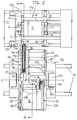
- the two identical and mirror-symmetrical to the symmetry plane y-y arranged mold guides G ′′ and the associated mold displacement devices of the changing table 27 are arranged, as can be seen in particular from FIG. 2.
- the computer controlling the change of the injection molds S is accommodated in the slide 27c.
- a vertical, rotatable drive shaft of a motor countersunk in the slide 27c meshes with a toothed ring of the turntable 27b via a pinion 27d.
- the two mutually identical casting mold shifting devices of the changing table 27 are formed by two endless transport chains 20 rotating around a vertical axis of rotation. Like the casting mold guides G ′′, these are arranged mirror-symmetrically to the vertical plane of symmetry yy in the carrier plate 27h.
- the two mold guides G ′′ of the changing table 27 are each formed by guide strips 19a, 19b, between which the one contact plate 41 of the injection mold S is immersed for guidance.
- the entraining run of the transport chain 20 runs on the lower edge of this contact plate 41.
- a vertical driver 20a of this run is with the Coupling member of this contact plate 41 can be coupled.
- the other contact plate 41 is supported on support rollers 62 of the relevant mold position, which are rotatably mounted in bearing strips 62 '.
- the transport chain 20 Since the transport chain 20, the guide strips 19a, 19b and the support rollers 62 on one half of the symmetry of the changing table 27 are arranged mirror-symmetrically to the organs mentioned on the other half of the symmetry of a changing table 27, the transport chain 20 is on the one mold position of the changing table 27 on the left Longitudinal edge and at the other parking space on the right longitudinal edge (Fig. 2).
- the aforementioned mirror-symmetrical arrangement of the transport chain 20, guide strips 19a, 19b and support rollers 62 to the plane of symmetry yy ensures that the named components of the rear half of the symmetry after rotation of the support plate 27h by 180 ° in the same spatial relationship to the adjacent mold clamping space F or to the adjacent mold position 44a are like the components mentioned on the other half of the symmetry before rotation.
- the two mold guides G '' of the changing table 27 in each case alternately form an identical transport path T; T 'with the mold guide G in the adjacent mold clamping space F or with the mold guide G ′′′ of a depot parking space 44, as shown in particular in FIGS. 7.9 recognizable.
- the injection molds S can be of different sizes, but in any case comprise a cuboid mold body 40 composed of standardized plates and two abutment plates 41 delimiting this mold body 40.
- One of the two abutment plates 41 is provided with a transverse groove 13a of rectangular cross section serving as a coupling element. Since the contact plates 41 protrude far beyond the mold body 40 and said transverse groove 13a is arranged in the immediate vicinity of the vertical end edge, this transverse groove 13a of an injection mold S located in the mold clamping space F is located in the area of the driver 20a of the adjacent transport chain 20 of the shuttle table 27 that this transport chain 20 laterally enters the transverse groove 13a as a result of its movement on the radius of the associated deflection wheel 26.
- the drivers 20a of the transport chain 20 are formed by hinge bolts of this chain and project upwards from the surface of the carrier plate 27h.
- a drive motor 21 is arranged in a receiving part 19c 'of the sliding bar 19c (FIG. 4).
- the timely drive of the transport chains 20 can be controlled by control elements which are attached to them and interact with start-stop switches of the shuttle table 27 via control tabs.
- the two transport chains 20 are mounted with their deflection wheels 26 in a sliding bar 19c, which in turn is displaceable in a guide bearing 91 of the carrier plate 27h of the changing table 27.
- the guide bar 19a of rectangular cross section is attached to the surface of the sliding bars 19c.
- the contact plate 41 is guided between the mutually facing vertical longitudinal edges of the two guide strips 19a and 19b.
- the driver 20a of the run of the transport chain 20 guided below the contact plate 41 plunges into the coupling element of the injection mold S, namely into the transverse groove 13a of the contact plate 41 of the coupling, in order to implement a coupling.
- the sliding bar 19c, the transport chain 20 with their deflection wheels 26 and the associated drive motor 21 form a structural unit which can be displaced in the guide bearing 91 in the direction of the respectively adjacent injection mold and with which an injection mold S resting on the shuttle table 27 is coupled via the driver 20a of the transport chain 20 is.
- a hydraulic cylinder 83 which is used to move the aforementioned structural unit, is arranged below the sliding bar 19c in a cavity 91 'of the carrier plate 27h.
- the actual hydraulic cylinder 83c is rigidly connected to the carrier plate 27h by means of a fastening piece 100.
- the piston rod 83a of the hydraulic cylinder 83 engages via a connecting piece 83b on the underside of the sliding bar 19c Taking along.
- each parking space of the shuttle table 27 is as follows: When the shuttle table travels from an injection molding machine to the depot 44 and vice versa, the two mold displacement devices are in the rearward position, that is to say in the rest position. As a result, the shuttle table 27 can move freely along the injection molding machines or along the cabinet forming the depot.
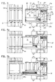
- the relevant mold shifting device is first out of its rest position, in which the front deflection wheel of the transport chain does not protrude forward of the carrier plate 27h of the changeable table 27 ( Fig. 5), by a ready shift in a clutch ready position (Fig. 5a, 5b, 4) in which the sliding bar 19c (Fig.
- a readiness shift in the above sense may also be necessary, because this readiness shift is the prerequisite for the injection mold S or transport unit to be transported to reach a position-appropriate position on the depot 44a or in the injection molding machine, to a certain extent the starting point when moving the injection mold S is brought forward on the shuttle table 27 by said readiness shift.
- FIG. 7 shows how, by rotating the changing table 27 by 180 °, the injection mold S1, which has now reached the front parking space of the changing table 27, can reach a position previously assumed (in FIG. 7) by the injection mold S2 to be replaced has been reached while this injection mold S2 to be replaced comes into a position in which the injection mold S1 to be replaced was previously.
- Fig. 8 shows how, by rotating the changing table 27 by 180 °, the injection mold S1, which has now reached the front parking space of the changing table 27, can reach a position previously assumed (in FIG. 7) by the injection mold S2 to be replaced has been reached while this injection mold S2 to be replaced comes into a position in which the injection mold S1 to be replaced was previously.
- FIG. 9 shows a stage of the mold change, in which the injection mold S2 to be replaced already enters the mold clamping area F from the adjacent parking space of the changing table 27 and this changing table 27 has moved to an empty depot parking space in the connected position and its support plate 27h has been rotated by 180 °.
- the replaced injection mold S1 can be moved into the depot position 44a on a transport path T 'now formed by the mold guide G ′′′ of said depot position 44a and the adjacent mold guide G' 'of the shuttle table 27.
- the mold guide G in the mold clamping space F is formed by support elements 18 of both mold carriers 12, 28 and by their clamping surfaces.
- FIGs. 5, 5a and 5b show chronologically successive stages of the transfer of an injection mold S from the changing table 27 to a depot parking space 44a.
- the injection mold is in a position suitable for driving the shuttle table on the guide 45 in its parking space.
- the sliding bar 19c with the organs of the sliding device combined into one unit together with that on the transport chain 20 coupled injection mold moved from the rear rest position to the front coupling standby position. Only in this position is the transport chain 20 set in motion, so that the injection mold, as can be seen in FIG. 5b, is pushed into a correct position on the mold position 44a.
Landscapes
- Engineering & Computer Science (AREA)
- Manufacturing & Machinery (AREA)
- Mechanical Engineering (AREA)
- Moulds For Moulding Plastics Or The Like (AREA)
- Injection Moulding Of Plastics Or The Like (AREA)
- Encapsulation Of And Coatings For Semiconductor Or Solid State Devices (AREA)
Claims (7)
- Dispositif de changement des moules d'une machine de moulage de matière plastique par injection qui comporte un moule de moulage par injection pouvant être serré dans l'espace de serrage des moules de l'unité de fermeture des moules et une unité de moulage par injection horizontale pouvant être posée par elle en position de dépose, et qui comprend une table de changement des moules (27) servant de chariot transporteur et comprenant au moins un emplacement destiné aux moules, lequel est muni d'un dispositif de déplacement des moules (20, 21, 26, G'') venant en prise avec un organe d'accouplement du moule de moulage par injection (S), cependant que la table de changement (27) peut être déplacée parallèlement à l'axe d'injection (x-x) dans un guidage rectiligne (45) situé du côté arrière pour être amenée dans une position de raccordement à la machine de moulage par injection ou à un dépôt de moules (44), et ce, d'une manière telle qu'un guidage de moules (G'') du dispositif de déplacement des moules (20, 21, 26, G'') constitue alternativement, avec le guidage de moules (G) présent dans l'espace de serrage des moules (F) et avec un guidage de moules (G‴) d'un emplacement de dépôt (44a), une voie de transport (T, T') qui s'étend transversalement par rapport à l'axe d'injection (x-x) et sur laquelle le moule de moulage par injection (S) peut être déplacé au moyen d'un élément conducteur (41) disposé sur lui, caractérisé par le fait que le dispositif de déplacement des moules (20, 21, 26, G'') de la table de changement (27), lequel comprend une chaîne transporteuse (20) munie d'un moteur d'entraînement (21), des roues de renvoi (26) et le guidage de moules (G''), est réalisé sous la forme d'une unité modulaire et qu'il peut être déplacé, à l'aide d'un entraînement (83) situé dans un logement de guidage (91) d'une plaque porteuse (27h) constituant l'emplacement, depuis une position de repos dans laquelle la chaîne transporteuse (20) est située à l'intérieur de la surface de base de la plaque porteuse (27h), jusque dans une position où il est prêt à l'accouplement, dans laquelle la chaîne transporteuse (20) fait saillie au-delà de la surface de base de la plaque porteuse (27h) et dans laquelle une roue de renvoi (26) est située dans la région de l'espace de serrage (F) de la machine de moulage de matière plastique par injection ou, respectivement, de l'emplacement de dépôt (44a).
- Dispositif de changement des moules selon la revendication 1, caractérisé par le fait que la chaîne transporteuse (20) est montée, avec ses roues de renvoi (26) et avec le guidage de moules (G''), dans une barre coulissante (19c) qui peut être déplacée dans le logement de guidage (91).
- Dispositif de changement des moules selon la revendication 2, caractérisé par le fait que le guidage de moules (G'') est constitué par deux baguettes de guidage (19a, 19b) dont l'une (19a) est située entre les deux brins de la chaîne transporteuse (20) et dont l'autre (19b) est située à côté du brin de la chaîne transporteuse (20) qui est du côté du bord, cependant que la distance entre les deux brins correspond à peu près à l'épaisseur de l'élément conducteur constitué par la plaque d'appui (41) du moule de moulage par injection (S), et que les baguettes de guidage (19a, 19b) sont disposées sur la barre coulissante (19c).
- Dispositif de changement des moules selon l'une des revendications précédentes, caractérisé par une disposition du dispositif de déplacement (20, 21, 26, G'') dans le logement de guidage (91) qui est telle que seuls les taquets d'entraînement verticaux (20a) de la chaîne transporteuse (20) fassent saillie au-delà de la surface de la plaque porteuse (27h) de la table de changement (27).
- Dispositif de changement des moules selon la revendication 4, caractérisé par le fait que les taquets d'entraînement (20a) peuvent être commandé, lors de leur déplacement circulaire sur la roue de renvoi (26), de façon à ce qu'ils pénètrent dans une rainure transversale (13a) de la plaque d'appui (41) du moule de moulage par injection (S), laquelle sert d'organe d'accouplement au moule de moulage par injection (S).
- Dispositif de changement des moules selon l'une des revendications précédentes, caractérisé par le fait que la table de changement (27) est pourvue de deux emplacements destinés aux moules qui sont munis chacun d'un dispositif de déplacement des moules (20, 21, 26, G''), cependant que les dispositifs de déplacement des moules identiques entre eux des emplacements sont disposés dans la plaque porteuse tournante (27h) en étant inversement symétriques par rapport au plan de symétrie vertical (y-y) de la table de changement (27), et qu'ils font saillie dans la surface en projection verticale du socle (11) de la machine à leur extrémité située du côté de la machine.
- Dispositif de changement des moules selon l'une des revendications précédentes, caractérisé par le fait que la chaîne transporteuse (20) comporte des goujons d'accouplement (20a) verticaux dont chacun, en vue de l'accouplement, peut être commandé de façon à pénétrer dans une rainure transversale (13a) de la plaque d'appui (41) du moule de moulage par injection à déplacer (S), à la suite d'un déplacement en arc de cercle sur la roue de renvoi de la chaîne transporteuse.
Priority Applications (1)
| Application Number | Priority Date | Filing Date | Title |
|---|---|---|---|
| AT90113480T ATE91456T1 (de) | 1986-08-05 | 1987-03-23 | Giessformwechseleinrichtung an kunststoffspritzgiessmaschinen. |
Applications Claiming Priority (2)
| Application Number | Priority Date | Filing Date | Title |
|---|---|---|---|
| DE19863626488 DE3626488A1 (de) | 1986-08-05 | 1986-08-05 | Giessformwechseleinrichtung an einer kunststoff-spritzgiessmaschine |
| DE3626488 | 1986-08-05 |
Related Parent Applications (3)
| Application Number | Title | Priority Date | Filing Date |
|---|---|---|---|
| EP87104257A Division-Into EP0255852B1 (fr) | 1986-08-05 | 1987-03-23 | Dispositif de changement de moule pour une machine d'injection de matière plastique |
| EP87104257A Division EP0255852B1 (fr) | 1986-08-05 | 1987-03-23 | Dispositif de changement de moule pour une machine d'injection de matière plastique |
| EP87104257.8 Division | 1987-03-23 |
Publications (3)
| Publication Number | Publication Date |
|---|---|
| EP0401872A2 EP0401872A2 (fr) | 1990-12-12 |
| EP0401872A3 EP0401872A3 (fr) | 1991-05-08 |
| EP0401872B1 true EP0401872B1 (fr) | 1993-07-14 |
Family
ID=6306733
Family Applications (2)
| Application Number | Title | Priority Date | Filing Date |
|---|---|---|---|
| EP90113480A Expired - Lifetime EP0401872B1 (fr) | 1986-08-05 | 1987-03-23 | Dispositif de changement de moule pour une machine d'injection de matière plastique |
| EP87104257A Expired - Lifetime EP0255852B1 (fr) | 1986-08-05 | 1987-03-23 | Dispositif de changement de moule pour une machine d'injection de matière plastique |
Family Applications After (1)
| Application Number | Title | Priority Date | Filing Date |
|---|---|---|---|
| EP87104257A Expired - Lifetime EP0255852B1 (fr) | 1986-08-05 | 1987-03-23 | Dispositif de changement de moule pour une machine d'injection de matière plastique |
Country Status (5)
| Country | Link |
|---|---|
| EP (2) | EP0401872B1 (fr) |
| AT (2) | ATE61536T1 (fr) |
| DE (4) | DE3645163C2 (fr) |
| HK (2) | HK99792A (fr) |
| SG (2) | SG97992G (fr) |
Families Citing this family (13)
| Publication number | Priority date | Publication date | Assignee | Title |
|---|---|---|---|---|
| DE3632449A1 (de) * | 1986-09-24 | 1988-04-07 | Karl Hehl | Kunststoff-spritzgiessmaschine mit zugehoerigem computer und datensichtgeraet |
| JP2644295B2 (ja) * | 1988-08-05 | 1997-08-25 | 東芝機械株式会社 | 射出成形機における金型交換装置 |
| US5833902A (en) * | 1996-10-24 | 1998-11-10 | Husky Injection Molding Systems Ltd. | Injection molding apparatus and process for changing mold elements |
| SE9701485L (sv) * | 1997-04-21 | 1998-05-11 | Pb Option Ab | Anordning vid formsprutningsverktyg för flermaterialformsprutning |
| JP2010012682A (ja) * | 2008-07-03 | 2010-01-21 | Shisuko:Kk | 金型のマルチ加熱冷却システム |
| CN114474571B (zh) * | 2021-12-31 | 2024-09-20 | 天津华夏联盛汽车部件有限公司 | 一种双出前雾灯注塑模具装置 |
| CN116277709A (zh) * | 2023-03-20 | 2023-06-23 | 佛山市顺德区震德精密机械有限公司 | 一种射出成型机 |
| CN116945484B (zh) * | 2023-09-20 | 2023-11-17 | 广州信强汽车配件有限公司 | 一种塑料注塑模具辅助安装装置 |
| CN117140839B (zh) * | 2023-11-01 | 2024-01-12 | 烟台龙港泵业股份有限公司 | 一种离心泵加工用壳体铸造装置 |
| CN118082102B (zh) * | 2024-03-29 | 2025-04-08 | 深圳市龙腾机械设备有限公司 | 一种可废料循环利用回收的多料多色注塑机及方法 |
| CN119502227B (zh) * | 2024-11-27 | 2025-06-27 | 鸿诚新材料科技泰州股份有限公司 | 一种基于epp材质包装箱的成型加工装置及方法 |
| CN121073024A (zh) * | 2025-07-16 | 2025-12-05 | 江西启烨物联技术有限公司 | 一种基于agv运载的注塑模具管理方法及系统 |
| CN121198856B (zh) * | 2025-11-26 | 2026-02-17 | 山东沃美智能装备有限公司 | 一种汽车横梁冲压加工机构 |
Family Cites Families (11)
| Publication number | Priority date | Publication date | Assignee | Title |
|---|---|---|---|---|
| DE1629746A1 (de) * | 1967-04-21 | 1971-02-04 | Desma Werke Gmbh | Spritzgiessanlage mit auswechselbaren Spritzgiessformen |
| JPS5567428A (en) * | 1978-11-16 | 1980-05-21 | Kobe Steel Ltd | Replacement of die block in injection molding machine and device thereof |
| JPS58119926U (ja) * | 1982-02-04 | 1983-08-16 | 相生精機株式会社 | 金型を用いる加工機械の金型交換装置 |
| EP0092685B2 (fr) * | 1982-04-26 | 1995-08-02 | Battenfeld GmbH | Dispositif de changement rapide et/ou serrage de moules pour machines à injection |
| DE3242169C2 (de) * | 1982-06-18 | 1984-07-19 | Karl 7298 Loßburg Hehl | Horizontale Formschließeinheit einer Kunststoff-Spritzgießmaschine mit Gießform-Wechselvorrichtung |
| DE3242054C2 (de) * | 1982-11-13 | 1990-01-25 | Karl 7298 Loßburg Hehl | An einer Formschließeinheit einer Kunststoff-Spritzgießmaschine zugeordnete Transportvorrichtung für eine Spritzgießform |
| US4529371A (en) * | 1984-06-06 | 1985-07-16 | Cincinnati Milacron Inc. | Mold changer for a press preferably an injection molding machine |
| DE8435785U1 (de) * | 1984-12-06 | 1985-04-25 | Mannesmann Demag Kunststofftechnik Zweigniederlassung der Mannesmann Demag AG, 8501 Schwaig | Werkzeug-Einbau- und Spannvorrichtung an einer Spritzgießmaschine |
| DE3508866C1 (de) * | 1985-03-13 | 1986-05-22 | Karl 7298 Loßburg Hehl | Spritzgießform für eine Formschließeinheit mit Formwechselvorrichtung |
| DE8527483U1 (de) * | 1985-09-26 | 1985-12-05 | BMB Maschinenbau GmbH, 4933 Blomberg | Werkzeug-Wechselvorrichtung |
| DE3617094A1 (de) * | 1986-05-21 | 1987-11-26 | Karl Hehl | Giessformwechseleinrichtung an einer gruppe von kunststoffspritzgiessmaschinen |
-
1986
- 1986-08-05 DE DE3645163A patent/DE3645163C2/de not_active Expired - Lifetime
- 1986-08-05 DE DE19863626488 patent/DE3626488A1/de active Granted
-
1987
- 1987-03-23 DE DE8787104257T patent/DE3768581D1/de not_active Expired - Lifetime
- 1987-03-23 AT AT87104257T patent/ATE61536T1/de not_active IP Right Cessation
- 1987-03-23 EP EP90113480A patent/EP0401872B1/fr not_active Expired - Lifetime
- 1987-03-23 DE DE9090113480T patent/DE3786561D1/de not_active Expired - Fee Related
- 1987-03-23 EP EP87104257A patent/EP0255852B1/fr not_active Expired - Lifetime
- 1987-03-23 AT AT90113480T patent/ATE91456T1/de not_active IP Right Cessation
-
1992
- 1992-09-29 SG SG979/92A patent/SG97992G/en unknown
- 1992-12-10 HK HK997/92A patent/HK99792A/xx not_active IP Right Cessation
-
1994
- 1994-07-13 SG SG93394A patent/SG93394G/en unknown
- 1994-10-20 HK HK113794A patent/HK113794A/xx not_active IP Right Cessation
Also Published As
| Publication number | Publication date |
|---|---|
| SG93394G (en) | 1995-01-13 |
| DE3768581D1 (de) | 1991-04-18 |
| DE3786561D1 (de) | 1993-08-19 |
| EP0255852A2 (fr) | 1988-02-17 |
| EP0401872A2 (fr) | 1990-12-12 |
| EP0401872A3 (fr) | 1991-05-08 |
| DE3645163C2 (en) | 1992-02-13 |
| EP0255852B1 (fr) | 1991-03-13 |
| DE3626488A1 (de) | 1988-02-18 |
| ATE91456T1 (de) | 1993-07-15 |
| SG97992G (en) | 1993-01-29 |
| ATE61536T1 (de) | 1991-03-15 |
| EP0255852A3 (en) | 1989-05-24 |
| DE3626488C2 (fr) | 1990-07-26 |
| HK113794A (en) | 1994-10-27 |
| HK99792A (en) | 1992-12-18 |
Similar Documents
| Publication | Publication Date | Title |
|---|---|---|
| DE3242169C2 (de) | Horizontale Formschließeinheit einer Kunststoff-Spritzgießmaschine mit Gießform-Wechselvorrichtung | |
| DE2421811C2 (de) | Formschließeinheit für eine Kunststoff-Spritzgießmaschine mit einem Schiebetisch | |
| AT394967B (de) | Einrichtung zum bespruehen der formflaechen mehrteiliger spritzgiess- und presswerkzeuge | |
| DE3222828A1 (de) | Verfahren zur verkuerzung der betriebs-ausfallzeit bei umruestung einer kunststoff-spritzgiessmaschine von einer temperierten spritzgiessform auf eine andere und kunststoffspritzgiessmaschine zur durchfuehrung des verfahrens | |
| DE4010024A1 (de) | Fertigungsanlage mit parallel- und nebenfoerderwegen | |
| DE2365148C3 (de) | Drehgießvorrichtung | |
| DE3645163C2 (en) | Changing mould for injection moulding | |
| AT403134B (de) | Formwechseleinrichtung für spritzgiessmaschinen | |
| EP1172170B1 (fr) | Dispositif pour changer des cadres de fixation dans une station d'usinage | |
| DE102004040019B4 (de) | Vorrichtung zur Herstellung von Wellrohren | |
| DE3720214A1 (de) | Spritzgiessmaschine | |
| DE3501000C2 (fr) | ||
| EP0665722B1 (fr) | Procede et dispositif pour convoyer des pieces planes | |
| EP0427222A2 (fr) | Appareil pour la fabrication de plaques d'impression | |
| DE2429529C3 (de) | Gießanlage | |
| EP0246398B1 (fr) | Dispositif de changement de moule pour un groupe de machine à injecter les matières plastiques | |
| DE3830964C2 (fr) | ||
| DE3242054C2 (de) | An einer Formschließeinheit einer Kunststoff-Spritzgießmaschine zugeordnete Transportvorrichtung für eine Spritzgießform | |
| DE3826875C2 (fr) | ||
| DE4219920C2 (de) | Formmaschine und automatisches Formwechselverfahren für eine Formmaschine | |
| DE1479044B2 (de) | Vorrichtung zum herstellen von schalen- oder becherfoermigen artikeln aus thermoplastischem kunststoff | |
| DE1260943B (de) | Anlage zum Herstellen von hohlen Schokoladenkoerpern | |
| DE3737598C2 (de) | Anlage zur formteilherstellung mit einem formwerkzeug | |
| DE3240962A1 (de) | Vorrichtung zum aufeinanderfolgenden automatischen versetzen von paletten | |
| DE3637166C2 (fr) |
Legal Events
| Date | Code | Title | Description |
|---|---|---|---|
| PUAI | Public reference made under article 153(3) epc to a published international application that has entered the european phase |
Free format text: ORIGINAL CODE: 0009012 |
|
| AC | Divisional application: reference to earlier application |
Ref document number: 255852 Country of ref document: EP |
|
| AK | Designated contracting states |
Kind code of ref document: A2 Designated state(s): AT CH DE FR GB IT LI NL |
|
| PUAL | Search report despatched |
Free format text: ORIGINAL CODE: 0009013 |
|
| AK | Designated contracting states |
Kind code of ref document: A3 Designated state(s): AT CH DE FR GB IT LI NL |
|
| 17P | Request for examination filed |
Effective date: 19910531 |
|
| 17Q | First examination report despatched |
Effective date: 19920910 |
|
| GRAA | (expected) grant |
Free format text: ORIGINAL CODE: 0009210 |
|
| AC | Divisional application: reference to earlier application |
Ref document number: 255852 Country of ref document: EP |
|
| AK | Designated contracting states |
Kind code of ref document: B1 Designated state(s): AT CH DE FR GB IT LI NL |
|
| REF | Corresponds to: |
Ref document number: 91456 Country of ref document: AT Date of ref document: 19930715 Kind code of ref document: T |
|
| REF | Corresponds to: |
Ref document number: 3786561 Country of ref document: DE Date of ref document: 19930819 |
|
| ET | Fr: translation filed | ||
| ITF | It: translation for a ep patent filed | ||
| GBT | Gb: translation of ep patent filed (gb section 77(6)(a)/1977) |
Effective date: 19931027 |
|
| PLBI | Opposition filed |
Free format text: ORIGINAL CODE: 0009260 |
|
| 26 | Opposition filed |
Opponent name: BATTENFELD GMBH Effective date: 19940413 |
|
| NLR1 | Nl: opposition has been filed with the epo |
Opponent name: BATTENFELD GMBH. |
|
| PLBN | Opposition rejected |
Free format text: ORIGINAL CODE: 0009273 |
|
| STAA | Information on the status of an ep patent application or granted ep patent |
Free format text: STATUS: OPPOSITION REJECTED |
|
| 27O | Opposition rejected |
Effective date: 19950703 |
|
| NLR2 | Nl: decision of opposition | ||
| ZE | Nl: corrections to earlier entries in headings pe - xe |
Free format text: PAT.BUL.01/96 HEADING RE,SECTION 2,PAGE 104,105 AND 106;DECISIONS ON OPPOSITIONS "OPPOSITIE AFGEWEZEN.OCTROOI HERROEPEN" CORR. "OPPOSITIE AFGEWEZEN.OCTROOI GEHANDHAAFD" |
|
| PGFP | Annual fee paid to national office [announced via postgrant information from national office to epo] |
Ref country code: GB Payment date: 19980309 Year of fee payment: 12 |
|
| PGFP | Annual fee paid to national office [announced via postgrant information from national office to epo] |
Ref country code: FR Payment date: 19980317 Year of fee payment: 12 |
|
| PGFP | Annual fee paid to national office [announced via postgrant information from national office to epo] |
Ref country code: NL Payment date: 19980330 Year of fee payment: 12 |
|
| PGFP | Annual fee paid to national office [announced via postgrant information from national office to epo] |
Ref country code: DE Payment date: 19990201 Year of fee payment: 13 |
|
| PGFP | Annual fee paid to national office [announced via postgrant information from national office to epo] |
Ref country code: AT Payment date: 19990322 Year of fee payment: 13 |
|
| PG25 | Lapsed in a contracting state [announced via postgrant information from national office to epo] |
Ref country code: GB Free format text: LAPSE BECAUSE OF NON-PAYMENT OF DUE FEES Effective date: 19990323 |
|
| PGFP | Annual fee paid to national office [announced via postgrant information from national office to epo] |
Ref country code: CH Payment date: 19990323 Year of fee payment: 13 |
|
| PG25 | Lapsed in a contracting state [announced via postgrant information from national office to epo] |
Ref country code: NL Free format text: LAPSE BECAUSE OF NON-PAYMENT OF DUE FEES Effective date: 19991001 |
|
| GBPC | Gb: european patent ceased through non-payment of renewal fee |
Effective date: 19990323 |
|
| PG25 | Lapsed in a contracting state [announced via postgrant information from national office to epo] |
Ref country code: FR Free format text: LAPSE BECAUSE OF NON-PAYMENT OF DUE FEES Effective date: 19991130 |
|
| NLV4 | Nl: lapsed or anulled due to non-payment of the annual fee |
Effective date: 19991001 |
|
| REG | Reference to a national code |
Ref country code: FR Ref legal event code: ST |
|
| PG25 | Lapsed in a contracting state [announced via postgrant information from national office to epo] |
Ref country code: AT Free format text: LAPSE BECAUSE OF NON-PAYMENT OF DUE FEES Effective date: 20000323 |
|
| PG25 | Lapsed in a contracting state [announced via postgrant information from national office to epo] |
Ref country code: LI Free format text: LAPSE BECAUSE OF NON-PAYMENT OF DUE FEES Effective date: 20000331 Ref country code: CH Free format text: LAPSE BECAUSE OF NON-PAYMENT OF DUE FEES Effective date: 20000331 |
|
| REG | Reference to a national code |
Ref country code: CH Ref legal event code: PL |
|
| PG25 | Lapsed in a contracting state [announced via postgrant information from national office to epo] |
Ref country code: DE Free format text: LAPSE BECAUSE OF NON-PAYMENT OF DUE FEES Effective date: 20010103 |
|
| PG25 | Lapsed in a contracting state [announced via postgrant information from national office to epo] |
Ref country code: IT Free format text: LAPSE BECAUSE OF NON-PAYMENT OF DUE FEES Effective date: 20050323 |