EP0402242A1 - Spiegeleinheit für eine Sonnenblende, insbesondere in einem Fahrgastraum eines Kraftfahrzeuges - Google Patents
Spiegeleinheit für eine Sonnenblende, insbesondere in einem Fahrgastraum eines Kraftfahrzeuges Download PDFInfo
- Publication number
- EP0402242A1 EP0402242A1 EP90401527A EP90401527A EP0402242A1 EP 0402242 A1 EP0402242 A1 EP 0402242A1 EP 90401527 A EP90401527 A EP 90401527A EP 90401527 A EP90401527 A EP 90401527A EP 0402242 A1 EP0402242 A1 EP 0402242A1
- Authority
- EP
- European Patent Office
- Prior art keywords
- cassette
- flap
- stop element
- rear face
- pins
- Prior art date
- Legal status (The legal status is an assumption and is not a legal conclusion. Google has not performed a legal analysis and makes no representation as to the accuracy of the status listed.)
- Granted
Links
- 238000009412 basement excavation Methods 0.000 claims description 7
- 238000004519 manufacturing process Methods 0.000 description 9
- 239000011324 bead Substances 0.000 description 2
- 230000015572 biosynthetic process Effects 0.000 description 2
- 230000006835 compression Effects 0.000 description 2
- 238000007906 compression Methods 0.000 description 2
- 239000011521 glass Substances 0.000 description 2
- 210000002445 nipple Anatomy 0.000 description 2
- 230000007423 decrease Effects 0.000 description 1
- 239000002184 metal Substances 0.000 description 1
- 239000011022 opal Substances 0.000 description 1
- 230000000284 resting effect Effects 0.000 description 1
Images

Classifications
-
- B—PERFORMING OPERATIONS; TRANSPORTING
- B60—VEHICLES IN GENERAL
- B60J—WINDOWS, WINDSCREENS, NON-FIXED ROOFS, DOORS, OR SIMILAR DEVICES FOR VEHICLES; REMOVABLE EXTERNAL PROTECTIVE COVERINGS SPECIALLY ADAPTED FOR VEHICLES
- B60J3/00—Antiglare equipment associated with windows or windscreens; Sun visors for vehicles
- B60J3/02—Antiglare equipment associated with windows or windscreens; Sun visors for vehicles adjustable in position
- B60J3/0204—Sun visors
- B60J3/0278—Sun visors structure of the body
- B60J3/0282—Sun visors structure of the body specially adapted for a courtesy mirror
Definitions
- the invention relates to a mirror cassette for a sun visor comprising a flap which is articulated on the cassette so that it can pivot between a closed position in which the flap covers the mirror and an open position in which the mirror is released, and which is locked in the open and closed positions by stop devices consisting of a fixed stop element formed on the cassette and a movable stop element moving with the shutter .
- German patent application DE-OS 37 03 511 a mirror cassette is known on which the articulation of the flap on the cassette is produced by means of pins mounted axially sliding in a bore formed on the flap and cooperating with cavities forming bearings provided in correspondence on the cassette.
- the flap is locked in the open and closed position using cooperating projections formed concentrically with the pivot axis, one of which is fixed and formed on the cassette, and the other being formed on the external end of the corresponding stud.
- a compression spring is provided so that the projection of the stud is firmly engaged with the corresponding projection of the cavity.
- French patent application 88 04 457 describes another cassette in which the pins of the joint are formed on the lateral edges of the cassette and cooperate with corresponding cavities formed on the edges of the flap.
- the shutter manufacturing mold requires retractable drawers for the formation of the cavities forming bearings and that, on the other hand, the mounting of the flap on the housing requires introducing one of the nipples into the corresponding cavity, then deforming by elasticity the flap so as to introduce the second stud force in its cavity, which can result in breaks, either of the flap or of a nipple.
- This mounting operation is all the more difficult as the flap is small and rigid.
- the shutter has cavities forming bearings and the cassette has pins cooperating with the bearings and in which the movable stop element of the shutter is constituted by a V-shaped edge.
- the fixed stop element of the cassette consists of a spring leaf applying to the flap a force directed towards the front face of the housing.
- the object of the present invention is to overcome these drawbacks and to propose a mirror cassette of the type mentioned above which, on the one hand, is easy to assemble, and which, on the other hand, eliminates the need for provide retractable drawers in the molds for manufacturing the housing and / or the cover, thereby making it possible to reduce the cost of the molds and increase the rate of manufacture of the molded parts.
- the articulation of the flap on the cassette comprises two aligned pins, parallel to one side of the flap, formed respectively on the lateral edges of the flap in the vicinity of said side and extending towards the outside of the flap, that the cassette has near its longitudinal upper edge a passage slot, intended to allow the mounting of the flap by the rear face of the cassette, which has a width at least equal to the thickness of the flap and a length at least equal to the distance separating the opposite edges of the flap carrying said pins and which has in each of its lateral end zones an open excavation on the side of the rear face of the cassette and intended to form a half-bearing for a stud of said flap and that the cassette is provided with at least one stirrup which is in abutment on the edge of the flap close to the alignment of said studs so as to maintain said studs in their respective half-bearings.
- the cavity forming a bearing of the prior art is replaced by the wall of the cassette on which the stud is resting and by the bracket holding the flap.
- the molds for manufacturing the cassette and the flap no longer require retractable drawers for the formation of the cavities, which makes it possible to increase the rate of use of these molds and to reduce the manufacturing cost thereof.
- the mounting of the flap on the housing is simplified. The edge of the shutter remote from the hinge axis is presented in the slot by the rear face of the housing and the shutter is made to slide in said slot until the pins are in abutment in the excavations. You can place the box horizontally with its rear side facing upwards and drop the shutter into the slot. Then just fix the bracket (s) to hold the shutter.
- the stirrup is constituted by an elastic blade which exerts on the flap a force directed towards the front face of the cassette. This arrangement avoids rattling of the shutter when the cassette is subjected to vibrations.
- the edge of the flap close to the alignment of the pins has at least one transverse movable stop element constituted by a V-shaped edge situated between two flats and the stirrup cooperates with said movable stop element and forms the fixed stop element of a stop device. Thanks to this structure, the manufacturing cost of the cassette is lower.
- the stirrup has the shape of a U, one end branch of which accommodates in a cavity formed in the cassette and opening onto the rear face of the latter, and the other end branch of which is free and cooperates. with the movable stop element.
- the cassette comprises two stirrups arranged in the vicinity of the lateral edges of the flap.
- the excavation has a semi-circular groove conforming to the corresponding stud and the wall of which is extended by two flat walls which deviate slightly towards the rear face of the cassette.
- the groove plays the role of a half-bearing for the corresponding stud, and the flared shape of the excavation facilitates the introduction of the flap during the mounting phase, thanks to the guidance of the studs by the flat walls.
- the cassette has a side wall opposite the end of each stud. This side wall increases the rigidity of the cassette.
- FIG. 1A shows a mirror cassette 2 embedded in a sun visor 1.
- Cassette 2 contains a mirror or glass 4 which can be covered by a pivotally mounted flap 3.
- the shutter 3 occupies its open position in FIG. 1A.
- Cassette 2 can additionally contain, but is not compulsory, lighting devices 5, for example in the form of small bulbs covered by an opal glass slide.
- Figure 1B shows the sun visor 1 with the flap 3 of the cassette 2 in the closed position.
- the shutter 3 has a flat or slightly curved outer face 6 and has a bead 7 on the periphery of its internal face which lodges in a groove 8 of rectangular shape formed near the periphery of the front face 9 of the cassette 2, when the shutter 3 is folded down.
- the flap 3 can pivot around a pivot axis 10 located in the vicinity of the longitudinal upper edge of the cassette 2 in the corresponding part of the groove 8.
- the male elements of the articulation of the flap 3 on the cassette 2 are constituted by two pins 12 aligned and parallel to the edge 21 of the flap 3 near the upper longitudinal edge of the cassette 2, which are formed respectively on the lateral edges 11 of the flap 3 perpendicular to the edge 21.
- the pins 12 are in the vicinity of this edge 21 and extend towards the outside of the shutter 3. They at least partially lodge in housings forming half-bearings provided in the opposite edges 13 of the cassette and opening into the groove.
- FIG. 2 shows a view of the front face of the cassette 2 without the flap 3 and having no lighting devices 5.
- the cassette 2 has in the vicinity of the pivot axis 10 a slot 14 which has a width at least equal to the thickness of the flap 3.
- the slot 14 opens on the front face 9 of the cassette 2 through an orifice 14a having a length at least equal to the length of the flap 3 between the two pins 12 and opens onto the rear face 15 of the cassette 2 through an orifice 15b having a length at least equal to the distance separating the free ends 16 of the two pins 12.
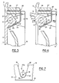
- the slot 14 can be opened opposite the ends 16 of the pins 12 and on the side of the lateral faces 17 of the cassette 2 (FIG. 7), but preferably the lateral faces 17 are closed off at the ends 16 of the pins 12 by walls 17a which reinforce the rigidity of the cassette 2.
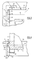
- each stud 12 is formed by a semi-cylindrical groove 18 delimited by the wall 18a of the corresponding edge 13 of the cassette 2 located near the stud 12 and on the side of the front face 9 of the cassette 2 relative to the pivot axis 10.
- This semi-cylindrical groove 18 is open on the side of the rear face 15 of the cassette 2 by virtue of flat walls 19 and 20 which extend the wall 18a, which delimit the end part of the slot 14 and which slightly deviate towards the rear face 15.
- the slot 14 thus has, in each of its zones adjacent to the studs 12, an excavation 20a opening onto the rear face 15 of the cavity 29 in the orifice 14b.
- the shutter 3 is mounted on the cassette 2 by presenting its edge remote from the studs 12 in the orifice 14b on the side of the rear face 15 of the cassette 2, then by sliding it into the slot 14 until the studs 12 are housed in their respective grooves 18.
- the edge 21 of the flap 3 adjacent to the pivot axis 10 comprises on the bead 7 adjacent a V-shaped edge 22 having two flats 23 and 24 which can be in contact, alternately, depending on the opening or closing position of the shutter 3, with a free end branch 25 of a metal blade 26, forming a spring and in the shape of a U, the second end branch 27 of this elastic blade 26 being fixed in a cavity 29 provided in the wall of the cassette 2 adjacent to the pivot axis 10 and opening onto the rear face 15, using latching means.
- the elastic blade 26 thus forms a stirrup which maintains the pins 12 of the flap 3 in their respective grooves 18.
- the elastic blade 26 exerts on the flap 3 via the flats 23 or 24 a force directed towards the front face 9 of the cassette 2, which eliminates vibrations and rattling of the flap 3 when the vehicle passes through the potholes.
- the elastic blade 26 in cooperation with the flats 23 and 24 constitutes a device for stopping the flap 3 at the positions of closing and opening, the free end branch 25 of the elastic blade 26 forming the fixed stop element and the edge 22 in combination with the flats 23 and 24 forming the movable stop element with the flap 3.
- two stop devices are provided, each of them being arranged in the vicinity of one of the lateral edges 11 of the shutter 3.
- the elastic blade 26 constitutes both the fixed stop element and the bracket for holding the shutter 3 on the cassette 2 preventing the shutter 3 from escaping. It goes without saying that the shutter 3 can be maintained around its pivot axis 10, using a bracket independent of the stop device and fixed on the cassette 2, in the vicinity of the axis of pivot 10 and on the side of the rear face 15 of the cassette. This stirrup can be placed in the vicinity of a stud 12 or in the vicinity of the edge 21 of the cassette 2.
Landscapes
- Engineering & Computer Science (AREA)
- Mechanical Engineering (AREA)
- Vehicle Step Arrangements And Article Storage (AREA)
- Rear-View Mirror Devices That Are Mounted On The Exterior Of The Vehicle (AREA)
- Passenger Equipment (AREA)
Applications Claiming Priority (2)
| Application Number | Priority Date | Filing Date | Title |
|---|---|---|---|
| FR8907473A FR2647733B1 (fr) | 1989-06-06 | 1989-06-06 | Cassette a miroir pour pare-soleil, notamment dans un habitacle d'automobile |
| FR8907473 | 1989-06-06 |
Publications (2)
| Publication Number | Publication Date |
|---|---|
| EP0402242A1 true EP0402242A1 (de) | 1990-12-12 |
| EP0402242B1 EP0402242B1 (de) | 1993-03-17 |
Family
ID=9382426
Family Applications (1)
| Application Number | Title | Priority Date | Filing Date |
|---|---|---|---|
| EP90401527A Expired - Lifetime EP0402242B1 (de) | 1989-06-06 | 1990-06-06 | Spiegeleinheit für eine Sonnenblende, insbesondere in einem Fahrgastraum eines Kraftfahrzeuges |
Country Status (6)
| Country | Link |
|---|---|
| US (1) | US4981348A (de) |
| EP (1) | EP0402242B1 (de) |
| JP (1) | JPH03213422A (de) |
| DE (1) | DE69001095T2 (de) |
| ES (1) | ES2040577T3 (de) |
| FR (1) | FR2647733B1 (de) |
Cited By (2)
| Publication number | Priority date | Publication date | Assignee | Title |
|---|---|---|---|---|
| DE4331884B4 (de) * | 1992-09-22 | 2008-10-16 | Prince Corp., Holland | Abdeckeinrichtung für einen Kosmetikspiegel |
| WO2010081030A1 (en) * | 2009-01-09 | 2010-07-15 | Johnson Controls Technology Company | Hinge assembly for vehicle interior trim component |
Families Citing this family (14)
| Publication number | Priority date | Publication date | Assignee | Title |
|---|---|---|---|---|
| ES2018929A6 (es) * | 1989-10-06 | 1991-05-16 | Gabas Cebollero Carlos | Espejo para visera parasol de vehiculos automoviles provisto de tapa abatible. |
| US5059016A (en) * | 1990-08-09 | 1991-10-22 | United Technologies Automotive | Vanity mirror assembly |
| ES2024963A6 (es) * | 1990-12-21 | 1992-03-01 | Ind Techno Matic Sa | Dispositivo de apertura y cierre semiautomatica para espejos de viserasparasol provistos de tapa abatible. |
| US5098150A (en) * | 1990-12-27 | 1992-03-24 | Prince Corporation | Visor cover hinge |
| JPH05229340A (ja) * | 1992-02-17 | 1993-09-07 | Koito Mfg Co Ltd | バニティミラー |
| JPH0650924U (ja) * | 1992-12-17 | 1994-07-12 | 株式会社ネオックスラボ | バニティミラ−のカバ−部開閉構造 |
| US5428513A (en) * | 1993-11-17 | 1995-06-27 | Prince Corporation | Covered vanity mirror and flexible circuit |
| US6174019B1 (en) * | 1998-02-26 | 2001-01-16 | Prince Corporation | Extruded visor control |
| DE10145856B4 (de) * | 2001-09-17 | 2005-09-08 | Huwil-Werke Gmbh Möbelschloss- Und Beschlagfabriken | Faltdeckel |
| US7093320B2 (en) * | 2001-10-01 | 2006-08-22 | Tager Jean M | Pin-less locks for sliding members |
| DE20214231U1 (de) | 2002-10-19 | 2003-02-27 | Intier Automotive Zippex GmbH, 74374 Zaberfeld | Sonnenblende für Fahrzeuge |
| JP4394403B2 (ja) * | 2003-09-12 | 2010-01-06 | 株式会社林技術研究所 | 自動車のサンバイザーに備えられるバニティミラーのリッドの回動開閉機構 |
| KR100582970B1 (ko) * | 2004-07-29 | 2006-05-25 | 삼성전자주식회사 | 도어개폐장치 및 그것을 갖는 전자기기 |
| SI3259425T1 (sl) * | 2015-02-17 | 2020-08-31 | Arturo Salice S.P.A. | Dvižni sistem za krila pohištva |
Citations (4)
| Publication number | Priority date | Publication date | Assignee | Title |
|---|---|---|---|---|
| US4213169A (en) * | 1978-11-09 | 1980-07-15 | Prince Corporation | Covered visor mirror |
| US4715644A (en) * | 1986-09-22 | 1987-12-29 | Irvin Industries, Inc. | Spring-loaded hinge assembly for vehicle accessories |
| EP0261989A2 (de) * | 1986-09-26 | 1988-03-30 | Prince Corporation | Sonnenblende |
| EP0268570A2 (de) * | 1986-11-20 | 1988-05-25 | Autopart Sweden Ab | Sonnenblende mit Spiegelbeleuchtung und schwenkbarer Abdeckung |
Family Cites Families (7)
| Publication number | Priority date | Publication date | Assignee | Title |
|---|---|---|---|---|
| US4000404A (en) * | 1973-03-21 | 1976-12-28 | Prince Corporation | Visor illuminated mirror |
| US4491899A (en) * | 1983-02-07 | 1985-01-01 | Prince Corporation | Visor cover assembly |
| DE3518751C1 (de) * | 1985-05-24 | 1986-08-14 | Gebr. Happich Gmbh, 5600 Wuppertal | Sonnenblende fuer Fahrzeuge |
| US4652982A (en) * | 1985-12-30 | 1987-03-24 | Prince Corporation | Illuminated vanity mirror assembly |
| US4796944A (en) * | 1986-09-22 | 1989-01-10 | Irvin Industries, Inc. | Spring-loaded hinge assembly for vehicle accessories |
| US4909562A (en) * | 1987-10-28 | 1990-03-20 | Koito Seisakusho Co., Ltd. | Vanity mirror on a visor having a spring-energized, controlled-movement mirror cover |
| JPH0650253Y2 (ja) * | 1988-11-11 | 1994-12-21 | 日産自動車株式会社 | 自動車用サンバイザー |
-
1989
- 1989-06-06 FR FR8907473A patent/FR2647733B1/fr not_active Expired - Lifetime
-
1990
- 1990-06-01 US US07/532,335 patent/US4981348A/en not_active Expired - Lifetime
- 1990-06-05 JP JP2145543A patent/JPH03213422A/ja active Pending
- 1990-06-06 DE DE9090401527T patent/DE69001095T2/de not_active Expired - Fee Related
- 1990-06-06 EP EP90401527A patent/EP0402242B1/de not_active Expired - Lifetime
- 1990-06-06 ES ES199090401527T patent/ES2040577T3/es not_active Expired - Lifetime
Patent Citations (4)
| Publication number | Priority date | Publication date | Assignee | Title |
|---|---|---|---|---|
| US4213169A (en) * | 1978-11-09 | 1980-07-15 | Prince Corporation | Covered visor mirror |
| US4715644A (en) * | 1986-09-22 | 1987-12-29 | Irvin Industries, Inc. | Spring-loaded hinge assembly for vehicle accessories |
| EP0261989A2 (de) * | 1986-09-26 | 1988-03-30 | Prince Corporation | Sonnenblende |
| EP0268570A2 (de) * | 1986-11-20 | 1988-05-25 | Autopart Sweden Ab | Sonnenblende mit Spiegelbeleuchtung und schwenkbarer Abdeckung |
Cited By (3)
| Publication number | Priority date | Publication date | Assignee | Title |
|---|---|---|---|---|
| DE4331884B4 (de) * | 1992-09-22 | 2008-10-16 | Prince Corp., Holland | Abdeckeinrichtung für einen Kosmetikspiegel |
| WO2010081030A1 (en) * | 2009-01-09 | 2010-07-15 | Johnson Controls Technology Company | Hinge assembly for vehicle interior trim component |
| US8701250B2 (en) | 2009-01-09 | 2014-04-22 | Johnson Controls Technology Company | Hinge assembly for vehicle interior trim component |
Also Published As
| Publication number | Publication date |
|---|---|
| FR2647733A1 (fr) | 1990-12-07 |
| EP0402242B1 (de) | 1993-03-17 |
| DE69001095D1 (de) | 1993-04-22 |
| DE69001095T2 (de) | 1993-08-12 |
| JPH03213422A (ja) | 1991-09-18 |
| FR2647733B1 (fr) | 1991-09-20 |
| ES2040577T3 (es) | 1993-10-16 |
| US4981348A (en) | 1991-01-01 |
Similar Documents
| Publication | Publication Date | Title |
|---|---|---|
| EP0402242B1 (de) | Spiegeleinheit für eine Sonnenblende, insbesondere in einem Fahrgastraum eines Kraftfahrzeuges | |
| EP0847710B1 (de) | Federgelenk für Haarartikel | |
| FR2477485A1 (fr) | Agencement de retroviseur a monter sur une portiere de vehicule et procede de montage | |
| FR2513578A1 (fr) | Pare-soleil, notamment pour vehicule automobile | |
| EP0459867B1 (de) | Gelenkverbindung zwischen einem Scheibenwischerarm und einem Scheibenwischerblatt | |
| FR3022042A1 (fr) | Monture de lunettes a branches amovibles clipsees | |
| EP2841986B1 (de) | Brillenfassung mit einem zierstück | |
| FR2610181A1 (fr) | Boitier a articulation invisible | |
| EP1047982A1 (de) | Uhrengehäuse | |
| CH667979A5 (en) | Adjustable fastener for bracelet - has curved central plate having groove in which arm of one part slides and locks in notches in groove | |
| FR2665268A1 (fr) | Monture de lunettes a charnieres elastiques. | |
| EP1059415B1 (de) | Gurtaufroller, Rolladen- oder Storebetätigungsmechanismus mit einem solchen Aufroller und Verfahren zur Herstellung eines solchen Aufrollers | |
| FR2588605A1 (fr) | Systeme manoeuvrable d'arret d'un battant de volet et ensemble de crochetage dudit battant. | |
| EP1152925A1 (de) | Stossfänger für ein kraftfahrzeug | |
| EP0962346B1 (de) | Abschlussvorrichtung für eine Öffnung einer Fahrzeugkarosserie, mit Aussengleitung und Herstellungsverfahren und entsprechende Montagevorrichtung | |
| FR2739816A1 (fr) | Projecteur pour vehicules | |
| EP0724052A1 (de) | Türgriff eines Kraftfahrzeugs zur schnellen Montage durch ein Keil-Nockensystem | |
| BE1003490A7 (fr) | Mecanisme d'entrainement de store. | |
| FR2782395A3 (fr) | Paire de lunettes | |
| FR2679047A1 (fr) | Charniere pour monture de lunettes. | |
| FR2706409A1 (fr) | Dispositif d'accrochage réversible d'un siège sur un plancher de véhicule automobile. | |
| FR2538921A1 (fr) | Monture pliante pour lunettes | |
| FR2704952A1 (fr) | Charnière élastique de lunettes. | |
| FR2774504A1 (fr) | Capot a volet monte pivotant, notamment pour platine de disjoncteur | |
| CH720432B1 (fr) | Dispositif de fixation d'un bracelet à une boîte de montre ayant une barrette |
Legal Events
| Date | Code | Title | Description |
|---|---|---|---|
| PUAI | Public reference made under article 153(3) epc to a published international application that has entered the european phase |
Free format text: ORIGINAL CODE: 0009012 |
|
| AK | Designated contracting states |
Kind code of ref document: A1 Designated state(s): BE DE ES FR GB IT NL SE |
|
| 17P | Request for examination filed |
Effective date: 19910510 |
|
| 17Q | First examination report despatched |
Effective date: 19920410 |
|
| GRAA | (expected) grant |
Free format text: ORIGINAL CODE: 0009210 |
|
| AK | Designated contracting states |
Kind code of ref document: B1 Designated state(s): BE DE ES FR GB IT NL SE |
|
| PG25 | Lapsed in a contracting state [announced via postgrant information from national office to epo] |
Ref country code: SE Effective date: 19930317 Ref country code: NL Effective date: 19930317 |
|
| REF | Corresponds to: |
Ref document number: 69001095 Country of ref document: DE Date of ref document: 19930422 |
|
| ITF | It: translation for a ep patent filed | ||
| GBT | Gb: translation of ep patent filed (gb section 77(6)(a)/1977) |
Effective date: 19930602 |
|
| PG25 | Lapsed in a contracting state [announced via postgrant information from national office to epo] |
Ref country code: BE Effective date: 19930630 |
|
| NLV1 | Nl: lapsed or annulled due to failure to fulfill the requirements of art. 29p and 29m of the patents act | ||
| REG | Reference to a national code |
Ref country code: ES Ref legal event code: FG2A Ref document number: 2040577 Country of ref document: ES Kind code of ref document: T3 |
|
| BERE | Be: lapsed |
Owner name: ROCKWELL AUTOMOTIVE BODY SYSTEMS-FRANCE EN ABREGE Effective date: 19930630 |
|
| PLBE | No opposition filed within time limit |
Free format text: ORIGINAL CODE: 0009261 |
|
| STAA | Information on the status of an ep patent application or granted ep patent |
Free format text: STATUS: NO OPPOSITION FILED WITHIN TIME LIMIT |
|
| 26N | No opposition filed | ||
| PGFP | Annual fee paid to national office [announced via postgrant information from national office to epo] |
Ref country code: GB Payment date: 19960531 Year of fee payment: 7 |
|
| PG25 | Lapsed in a contracting state [announced via postgrant information from national office to epo] |
Ref country code: GB Free format text: LAPSE BECAUSE OF NON-PAYMENT OF DUE FEES Effective date: 19970606 |
|
| GBPC | Gb: european patent ceased through non-payment of renewal fee |
Effective date: 19970606 |
|
| PGFP | Annual fee paid to national office [announced via postgrant information from national office to epo] |
Ref country code: ES Payment date: 20000620 Year of fee payment: 11 |
|
| PG25 | Lapsed in a contracting state [announced via postgrant information from national office to epo] |
Ref country code: ES Free format text: LAPSE BECAUSE OF NON-PAYMENT OF DUE FEES Effective date: 20010607 |
|
| REG | Reference to a national code |
Ref country code: FR Ref legal event code: CD Ref country code: FR Ref legal event code: CA |
|
| PGFP | Annual fee paid to national office [announced via postgrant information from national office to epo] |
Ref country code: DE Payment date: 20021127 Year of fee payment: 13 |
|
| PGFP | Annual fee paid to national office [announced via postgrant information from national office to epo] |
Ref country code: FR Payment date: 20021129 Year of fee payment: 13 |
|
| REG | Reference to a national code |
Ref country code: ES Ref legal event code: FD2A Effective date: 20030203 |
|
| PG25 | Lapsed in a contracting state [announced via postgrant information from national office to epo] |
Ref country code: DE Free format text: LAPSE BECAUSE OF NON-PAYMENT OF DUE FEES Effective date: 20040101 |
|
| PG25 | Lapsed in a contracting state [announced via postgrant information from national office to epo] |
Ref country code: FR Free format text: LAPSE BECAUSE OF NON-PAYMENT OF DUE FEES Effective date: 20040227 |
|
| REG | Reference to a national code |
Ref country code: FR Ref legal event code: ST |
|
| PG25 | Lapsed in a contracting state [announced via postgrant information from national office to epo] |
Ref country code: IT Free format text: LAPSE BECAUSE OF NON-PAYMENT OF DUE FEES Effective date: 20050606 |