EP0402576B1 - Bouclier pour un procédé de creusement de tunnel de petit diamètre - Google Patents
Bouclier pour un procédé de creusement de tunnel de petit diamètre Download PDFInfo
- Publication number
- EP0402576B1 EP0402576B1 EP90105163A EP90105163A EP0402576B1 EP 0402576 B1 EP0402576 B1 EP 0402576B1 EP 90105163 A EP90105163 A EP 90105163A EP 90105163 A EP90105163 A EP 90105163A EP 0402576 B1 EP0402576 B1 EP 0402576B1
- Authority
- EP
- European Patent Office
- Prior art keywords
- filling material
- seal
- segment ring
- shield machine
- seal device
- Prior art date
- Legal status (The legal status is an assumption and is not a legal conclusion. Google has not performed a legal analysis and makes no representation as to the accuracy of the status listed.)
- Revoked
Links
- 238000000034 method Methods 0.000 title claims description 22
- 230000005641 tunneling Effects 0.000 title claims description 12
- 239000000463 material Substances 0.000 claims description 49
- XLYOFNOQVPJJNP-UHFFFAOYSA-N water Substances O XLYOFNOQVPJJNP-UHFFFAOYSA-N 0.000 claims description 20
- 238000011010 flushing procedure Methods 0.000 claims description 10
- 239000002689 soil Substances 0.000 claims description 9
- 238000004891 communication Methods 0.000 claims description 8
- 238000002347 injection Methods 0.000 claims description 6
- 239000007924 injection Substances 0.000 claims description 6
- 238000007789 sealing Methods 0.000 claims description 5
- 238000009412 basement excavation Methods 0.000 claims description 2
- 239000011800 void material Substances 0.000 description 25
- 230000002093 peripheral effect Effects 0.000 description 9
- 230000006835 compression Effects 0.000 description 7
- 238000007906 compression Methods 0.000 description 7
- 239000011440 grout Substances 0.000 description 3
- 230000035515 penetration Effects 0.000 description 3
- 230000004323 axial length Effects 0.000 description 2
- 239000003795 chemical substances by application Substances 0.000 description 2
- 230000015572 biosynthetic process Effects 0.000 description 1
- 230000015556 catabolic process Effects 0.000 description 1
- 239000002801 charged material Substances 0.000 description 1
- 238000006243 chemical reaction Methods 0.000 description 1
- 238000010276 construction Methods 0.000 description 1
- 238000007796 conventional method Methods 0.000 description 1
- 238000006731 degradation reaction Methods 0.000 description 1
- 238000006073 displacement reaction Methods 0.000 description 1
- 230000009977 dual effect Effects 0.000 description 1
- 239000002184 metal Substances 0.000 description 1
- 238000012986 modification Methods 0.000 description 1
- 230000004048 modification Effects 0.000 description 1
- 230000002035 prolonged effect Effects 0.000 description 1
- -1 rounded gravels Substances 0.000 description 1
- 238000007711 solidification Methods 0.000 description 1
- 230000008023 solidification Effects 0.000 description 1
- 239000000126 substance Substances 0.000 description 1
Images





Classifications
-
- E—FIXED CONSTRUCTIONS
- E21—EARTH OR ROCK DRILLING; MINING
- E21D—SHAFTS; TUNNELS; GALLERIES; LARGE UNDERGROUND CHAMBERS
- E21D9/00—Tunnels or galleries, with or without linings; Methods or apparatus for making thereof; Layout of tunnels or galleries
- E21D9/06—Making by using a driving shield, i.e. advanced by pushing means bearing against the already placed lining
- E21D9/0607—Making by using a driving shield, i.e. advanced by pushing means bearing against the already placed lining the shield being provided with devices for lining the tunnel, e.g. shuttering
-
- E—FIXED CONSTRUCTIONS
- E04—BUILDING
- E04G—SCAFFOLDING; FORMS; SHUTTERING; BUILDING IMPLEMENTS OR AIDS, OR THEIR USE; HANDLING BUILDING MATERIALS ON THE SITE; REPAIRING, BREAKING-UP OR OTHER WORK ON EXISTING BUILDINGS
- E04G21/00—Preparing, conveying, or working-up building materials or building elements in situ; Other devices or measures for constructional work
- E04G21/02—Conveying or working-up concrete or similar masses able to be heaped or cast
- E04G21/04—Devices for both conveying and distributing
- E04G21/0418—Devices for both conveying and distributing with distribution hose
- E04G21/0472—Details of connection of the hose to the formwork, e.g. inlets
-
- E—FIXED CONSTRUCTIONS
- E21—EARTH OR ROCK DRILLING; MINING
- E21D—SHAFTS; TUNNELS; GALLERIES; LARGE UNDERGROUND CHAMBERS
- E21D9/00—Tunnels or galleries, with or without linings; Methods or apparatus for making thereof; Layout of tunnels or galleries
- E21D9/06—Making by using a driving shield, i.e. advanced by pushing means bearing against the already placed lining
- E21D9/0635—Tail sealing means, e.g. used as end shuttering
Definitions
- the present invention relates to a shield machine for use in a shield tunneling method for constructing a small diameter tunnel with an inside diameter which is typically on the order of 1.5 m or less and which combines a set of three 120° arcuate segments into a so-called segment ring.
- a shield machine for either manually or mechanically excavating the ground face in front of the shield machine, substantially under unpressurized condition, to assemble within the shield machine a set of three 120° arcuate segments into a so-called segment ring, and to connect back-filling pipes with grout holes extending through the wall of the segments for charging a back-filling material, e.g. rounded gravels, grout or the like, into a so-called tail void which is an annular gap defined between the outer periphery of the segment ring and the surrounding soil.
- a back-filling material e.g. rounded gravels, grout or the like
- the radial dimension of the tail void in order to allow an assembly within the shield machine of a set of segments into a segment ring, it is necessary for the radial dimension of the tail void to be at least about one half of the thickness of the segment, and to be typically as large as the segment thickness. Then, unlike in a conventional method wherein a segment ring is formed of four or more segments, it is of particular importance to uniformly charge the back-filling material into the tail void, and to achieve a sufficient hardening of the charged material therein.
- an earth pressure balancing method is sometimes used together wherein mud making agents are supplied to the face to balance the resulting force with the pressure applied to the face.
- the earth pressure balancing method is often advantageous in that, as compared with the above-mentioned auxiliary measures, it is far economical and yet allows the required work to be performed in a facilitated manner.
- the back-filling material after the back-filling material has been charged into the tail void, the back-filling material often exhibits a problematic tendency to collapse prior to completion of its hardening, which is mainly due to a substantial amount of mud making agent with a high water content, and which more or less results in that the required grouting function of the back-filling material cannot be sufficiently achieved.
- a shield machine for use in a shield tunneling method for constructing a small diameter tunnel.
- the back-filling material charged into the annular gap between the outer periphery of the segment ring and surrounding soil can be sufficiently compressed by the seal device which can be moved axially within the annular gap, enabling formation of a layer of uniform, fine and high strength back-filling material over the entire outer periphery of the segment ring, even under a high water content in a poor ground. It thus becomes possible to effectively and positively prevent undesired collapse of the back filling material layer prior to the completion of its hardening, even under penetration of an excessive amount of water from the ground.
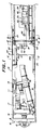
- FIGs. 1 to 4 a shield machine 10 according to a preferred embodiment of the present invention.
- the shield machine 10 makes use of an earth pressure balancing system, wherein the soil is mechanically excavated at the face while the face pressure and the pressure of the muck are balanced with each other.
- the shield machine 10 comprises a front portion 11 and a rear portion 12 each having a cylindrical form.
- the two portions 11 and 12 are connected with each other in an articulated manner, by means of a plurality of jacks 13 for adjusting their mutual orientation.
- the front portion 11 of the shield machine 10 adjacent to its front end is provided with a bulkhead 14, and a cutter 15 and a copy cutter 16 for mechanically excavating the natural ground A at the face, each attached to the bulkhead 14, as well as a drive motor 17 for driving the cutters 15 and 16.
- a screw conveyer 18 which serves to discharge muck during the excavation by the cutters 15 and 16.
- the conveyer 18 extends through the bulkhead 14 such that its front end for receiving the muck protrudes into a space between the rear surface of the cutter 15 and the front surface of the bulkhead 14.
- the rear portion 12 of the shield machine has a space allowing various works to be performed therein, including an assembly of a set of three 120° arcuate segments into a segment ring 20.
- the rear portion 12 is further provided, in addition to the above-mentioned tail skin plate 22, with an annular seal device 23 slidably disposed within a so-called tail void, which is an annular gap between the inner periphery of the tail skin plate 22 and the outer periphery of the segment ring 20, as well as an actuator 24 which, after the back-filling material has been charged into the tail void, serves to compresses the back-filling material by causing the seal device 23 to slide axially away from the face.
- tail void is an annular gap between the inner periphery of the tail skin plate 22 and the outer periphery of the segment ring 20, as well as an actuator 24 which, after the back-filling material has been charged into the tail void, serves to compresses the back-filling material by causing the seal device 23 to slide axially away from the face.
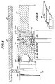
- the press ring 21 is connected to the rods 19b of the shield jacks 19 so that an axial thrust is applied thereto through the rod 19b, in a manner known per se .
- a spherical convex portion 25 is formed at the tip end of each rod 19b, while a spherical concave portion 26 corresponding to the convex portion 25 is formed at the end surface of the press ring 21.
- the convex portions 25 are fitted into the respective concave portions 26, so that even when the longitudinal axes of the rods 19b are not exactly in parallel with the longitudinal axis of the press ring 21 for some reason or others, only the axial thrust can be transmitted from the rods 19b to the press ring 21.
- a retainer ring 27 is secured to the end surface of the press ring 21 in order to prevent disengagement of the convex portions 25 from the concave portions 26, and maintain them in engagement with each other.
- the pres ring 21 is composed of a pair of ring members 21a on the side of the shield jack 19, and a rear ring member 21b on the side of the segment ring 20.
- the opposed end surfaces of the ring members 21a and 21b are provided with a concave portion 28 and a convex portion 29, respectively, which are in abutment with each other with an annular thrust bearing member 30 arranged therebetween, such that the ring members 21a, 21b can be relatively rotated.
- a retainer ring 32 is secured to the end surface of the front ring member 21a, and is brought into engagement with the rear ring member 21b behind the convex portion 29, whereby the ring members 21a and 21b are prevented from undesired relative axial movement.
- the buffer ring 33 is subjected to a compression deformation when acted upon the axial thrust, such that the thrust can be uniformly applied to and distributed along the entire end surface of the segment ring 20 on its face side, thereby to prevent an undesired local stress concentration on the end surface of the segment ring 20, and to positively protect the segment ring 20 from damages.
- a plurality of gang fittings 34 are threadedly connected onto the outer periphery of the rear ring members 21b so as to protrude toward and beyond the tip end portion of the segment ring 20.
- Each fitting 34 is provided with a tapered inner periphery 34a which may serve as a guide surface of the segment ring 20 (Fig. 6).
- each gang fittings 34 engages with the segment ring 20 along its inner periphery 34a to guide the movement of the press ring 21 toward the segment ring 20 into a proper position where their axes are in exact alignment with each other.
- a set of three gang fittings 34 are disposed at an equiangular distance of 120°.
- the press ring 21 at its lower end portion may be provided with at least one support roller assembly 40.
- the assembly 40 includes a roller 41 adapted to roll along the inner surface of the tail skin plate 22, a bracket 42 for rotatably supporting the roller 41, and a compression coil spring 43 which urges the bracket 42 toward the inner surface of the tail skin plate 22.
- the coil spring 43 has its lower end in engagement with a metal seat member 44, which is connected with a projection 42a formed on the upper end portion of the bracket 42, and its upper end in engagement with an adjusting bolt 45.
- the force of the spring 43 acting on the bracket 42 can be adjusted so as to balance the dead weight of the press ring 21 and the force of the spring 43, to vertically position the press ring 21 at a location where its longitudinal axis is in exact alignment with that of the shield machine 10.
- seal device 23 which is disposed between the inner periphery of the tail skin plate 22 and the outer periphery of the segment ring 20, will be described hereinafter, with reference to the embodiments shown in Figs. 10 to 13.
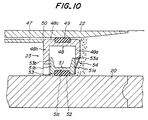
- the seal device 23 is disposed at the free end of an inner cylinder 47 which extends along the inner periphery of the tail skin plate 22, and which is connected to the actuator 24.
- the seal device 23 is moved axially rearwardly along the inner periphery of the tail skin plate 22, to compress the back-filling material charged into the tail void in a manner to be described below.
- an outer retainer member 48 is provided as an integral extension at the free end of the inner cylinder 47.
- the retainer member 48 includes a pair of end walls 48a, 48b extending radially inwardly, as well as a peripheral wall 48c connecting the end walls 48a, 48b with each other.
- Each end walls 48a, 48b of the outer retainer member 48 has an inner diameter which is slightly greater than the outer diameter of the segment ring 20.
- a seal ring 49 forming an outer seal member is disposed between the outer periphery of the peripheral wall 48c and the inner periphery of the tail skin plate 22. The seal ring 49 serves to seal a gap 50 between the retainer member 48 and the tail skin plate 22.
- the end walls 48a, 48b and the peripheral wall 48c of the outer retainer member 48 define a space which is made to open toward the outer periphery of the segment ring 20 for accommodating therein an inner retainer member 51.
- the inner retainer member 51 includes a pair of end walls 51a, 51b extending radially outwardly, as well as a peripheral wall 51c connecting the end walls 51a, 51b with each other.
- Each end walls 51a, 51b of the inner retainer member 51 has an outer diameter which is slightly smaller than the inner diameter of the peripheral wall 48c of the outer retainer member 48, e.g. by about 20 mm.
- a seal ring 52 forming an annular inside seal member is disposed between the inner periphery of the peripheral wall 51c and the outer periphery of the segment ring 20 to seal a gap 53 between the peripheral wall 51c and the segment ring 20.
- the outer and inner seal rings 49, 52 are brought into a surface contact with the tail skin plate 22 and the segment ring 20, respectively, over a sufficient axial length.
- the radial size of the gap between the inner periphery of the tail skin plate 22 and the outer periphery of the segment ring 20 is not necessarily constant in the circumferential direction.
- the above-mentioned arrangement of the outer and inner retainer rings 48, 51 in the embodiment shown in Fig. 10 ensures that the inner retainer member 51 can be relatively displaced in the radial direction with reference to the outer retainer member 48, in an eccentric manner, to compensate for possible change in the radial size of the gap as seen in the circumferential direction.
- an intermediate seal member 54 composed of a resilient sheet member is preferably provided to seal at least the gap 53a on the compression side extending in the direction in which the back-filling material charged into the tail void is compressed.
- the intermediate seal member 54 includes an outer periphery which is fixed to the end surface of the end wall 48a on the compression side of the outer retainer member 48, and an inner periphery which is fixed to the end surface of the end wall 51a on the compression side of the inner retainer member 51.
- the intermediate seal member 54 can thus be deformed following the radial displacement of the inner retainer member 51.
- the above-described annular seal device 23 having the outer seal member 49, the inner seal member 52 and the intermediate seal member 54 achieves a satisfactory sealing performance between the shield machine 10 and the tail void charged with the back-filling material, effectively and reliably preventing intrusion or leakage of water from the tail void into the shield machine.
- the seal device 23 is basically the same in its arrangement as the previous one, so that corresponding elements are denoted by the same reference numerals.
- the seal device 23 according to the present example includes outer and inner retainer members 48, 51 respectively disposed at the free end of the inner cylinder 47 which, in turn, is connected to the actuator 24.
- the outer and inner retainer members 48, 51 are provided with seal members in the form of seal lips 49, 52, respectively.
- the seal lip 49 provided for the outer retainer member 48 is threadedly connected with the end wall 48a of the retainer member 48, at the proximal end on the inner periphery side thereof, and is in seal contact with the inner periphery of the tail skin plate 22 at its lip section on the outer periphery side.
- the seal lip 52 provided for the inner retainer member 51 at the inner side is threadedly connected with the end wall 51a of the retainer member 51 at the proximal end on the outer periphery side thereof, and is in seal contact with the outer periphery of the segment ring 20 at its lip section on the inner periphery side.
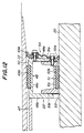
- Fig. 12 illustrates still another example of the seal device 23.
- the seal device 23 of this example has an arrangement which combines the structures explained above with reference to Figs. 10 and 11, so that corresponding elements are denoted by the same reference numerals.
- the seal device 23 of this example also has outer and inner retainer members 48, 51 respectively disposed at the free end of the inner cylinder 47 which, in turn, is connected to the actuator 24.
- the seal member provided for the outer retainer member 48 is composed of a seal lip 49a attached to the end wall 48a, and a seal ring 49b attached to the peripheral wall 48c.
- the seal ring 49b may have a saw-toothed cross-section on its outer periphery, so as to be in line contact with the inner periphery of the tail skin plate 22.
- the seal member provided for the inner retainer member 51 is composed of a seal lip 52a attached to the end wall 51a, and a seal ring 52b attached to the peripheral wall 51c.
- the seal ring 52b also may have a saw-toothed cross-section on its inner periphery, so as to be in line contact with the outer periphery of the segment ring 20.
- each of the outer and inner seal members has a combination of the seal lip and seal ring, a dual seal arrangement is formed along the inner periphery of the tail skin plate 22 and the outer periphery of the segment ring 20, with the result that an even more reliable seal performance can be achieved between the tail void and the shield machine 10.
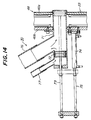
- the charging device of this example is arranged in combination with the above-mentioned seal device 23 and includes a cylinder 71 fixedly connected to the outer retainer member 48 axially through the seal device 23.
- a piston 72 is slidably arranged within the cylinder 71 and connected to a rod 73 which is axially reciprocably driven by an actuator 74 through its output rod 75.
- the cylinder 71 extends from the end wall 48b of the retainer member 48 toward the face, and has its cylinder bore opening end which may slightly project from the end wall 48a into the tail void.
- a supply pipe 76 for charging the back-filling material into the tail void
- an injection pipe 77 for injecting flushing water into the cylinder 71 and the supply pipe 76.
- the supply pipe 76 is led to a carriage 78 for carrying the back-filling material (see Fig. 1), and connected to a back-filling material storage tank 79 and a water storage tank 80 on the carriage 78 through gate valve 81, pump 82 and switching valve 83.
- the flushing water injection pipe 77 is connected to a water supply tank 84 also mounted on the carriage 78, through gate valve 85 and pump 86.
- the opening end of the cylinder 71 is brought into communication with the supply pipe 76, while a communication between the pipes 76 and 77 is interrupted.
- the piston 72 assumes a flushing position indicated by imaginary lines, the end of the cylinder 71 is closed by the piston 72 to interrupt the communication between the supply pipe 76 and the tail void, while bringing the supply pipe 76 into communication with the injection pipe 77.
- the cylinder 71 and the piston 72 may each have a flat cross-section so as to be readily accommodated in the internal space of the seal device 23.
- the actuator 74 for actuating the drive rod 73 is fixedly connected to the end wall 48b of the outer retainer member 48 such that it is arranged in a circumferentially juxtaposed relationship with the cylinder 71.
- the output rod 75 of the actuator 74 and the drive rod 73 are connected to each other in a U-shaped fashion, with the result that the charging device 70 of a compact structure can be readily accommodated within a limited narrow space of the tail void.
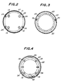
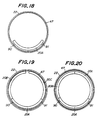
- a set of three 120° arcuate segments 20A, 20B, 20C are introduced into the tail portion of the shield machine 10 and assembled therein into a unit segment ring 20.
- an inverted segment 20A is placed on support members 90, 91 disposed at the bottom region of the inner cylinder 47 within the tail skin plate 22.
- each side segment 20B, 20C is brought into abutment against the inverted segment 20A in an end-to-end relationship, while tentatively retaining each upper end of the side segments 20B, 20C along the inner periphery of the inner cylinder.
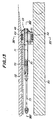
- a hydraulic pressure is applied to the shield jack 19, with the press ring 21 in engagement with the front end surface of the segment ring 20, as shown in Fig. 1.
- the rod 19b of the shield jack 19 is extended, as shown in Fig. 16, by a predetermined stroke corresponding to the axial length of the segment ring 20.
- the resultant reaction force serves to advance the shield machine 10, such that the cutters 15 and 16 at the front portion of the shield machine 10 are urged against the face to excavate the natural ground by an amount corresponding to a unit stroke of the shield machine 10, as shown in Fig. 16.
- the shield machine 10 advances together with the actuator 24, since the latter is fixedly connected to the inner periphery of the tail skin plate 22. It is therefore desirable to maintain the seal device 23 at an axially constant location relative to the segment ring 20, despite the advancement of the shield machine 10, to thereby prevent collapse of the back-filling material before completion of its hardening. It is for this reason that the actuator 24 is operated synchronously with the shield jack 19 to push out the rod 24a of the actuator toward the tail void by a stroke corresponding to an operating stroke of the shield jack 19.
- the actuator 24 is operated to retract the rod 24a to displace the seal device 23 axially toward the face relative to the segment ring 20.
- a space for charging a new back-filling material is formed between the seal device 23 and the back-filling material which has already been hardened.
- the actuator 74 is actuated to move the piston 72 up to the charging position between the supply pipe 76 and the flushing water pipe 77, as shown by solid lines in Fig.
- the piston 72 is moved by the actuator 74 up to the flushing position at the tip end of the cylinder 71, as shown by imaginary lines in Fig. 14, while at the same time the valve 83 included in the supply pipe 76 is switched so as to bring the cylinder 71 into communication with the water storage tank 80.
- the flushing water within the tank 84 is pressurized by the pump 86 and injected into the cylinder 71 via the injection pipe 77 to wash and clean the interior of the supply pipe 76.
- the flushing water is then discharged into the storage tank 80 via the supply pipe 76.
- the rod 24a of the actuator 24 is further extended from the position shown in Fig. 16 to press out the seal device 23 toward the tail void, in order to fully compress the back-filling material.
- This compression allows excessive water contained in the back-filling material to be squeezed out and absorbed into the natural soil A, effectively preventing the collapse of the back-filling material before completion of its hardening, and thereby forming a fine and minute back-filling material layer.
- a desired small diameter tunnel can sequentially be built up by repeating the above-described process steps of assembling another sets of three 120° arcuate segments, advancing the shield machine 10, and charging and compressing the back-filling material.
- the back-filling material is charged into the annular gap between the outer periphery of the segment ring and the inner periphery of the natural soil, and is sufficiently compressed by means of the seal device which is axially movable within the gap.
- This makes it possible to form a uniform, fine and high strength back-filling material layer over the entire outer periphery of the segment ring even in a poor ground with a high water content, which effectively prevents the collapse of the back-filling material before completion of its hardening as a result of penetration of excessive water from the surrounding soil. Consequently, a desired small-diameter tunnel can be economically constructed by applying the earth pressure balance shield method to the small-diameter shield work using 120° arcuate segments.
- the back-filling material supply pipe may be connected to a grout hole on the inner periphery of the segment in a conventional manner known per se , to charge the back-filling material into the tail void through the segment wall, provided that the seal device achieves the combined sealing and compression function for the back-filling material within the tail void.
Landscapes
- Engineering & Computer Science (AREA)
- Mining & Mineral Resources (AREA)
- Architecture (AREA)
- Environmental & Geological Engineering (AREA)
- Life Sciences & Earth Sciences (AREA)
- General Life Sciences & Earth Sciences (AREA)
- Geochemistry & Mineralogy (AREA)
- Geology (AREA)
- Mechanical Engineering (AREA)
- Civil Engineering (AREA)
- Structural Engineering (AREA)
- Lining And Supports For Tunnels (AREA)
Claims (3)
- Bouclier destiné à être utilisé dans un procédé de construction de tunnels au moyen de boucliers en vue de construire un tunnel de faible diamètre, comprenant un voussoir annulaire (20) à l'intérieur d'une partie de queue (12) du bouclier (10) qui est définie par une jupe de queue (22) de celui-ci, un matériau du remblayage étant chargé dans un intervalle annulaire formé entre le pourtour extérieur du voussoir annulaire (20) et le sol brut qui entoure le voussoir annulaire, ledit bouclier comprenant :a) des moyens pour charger le matériau de remblayage dans ledit intervalle annulaire depuis l'intérieur du bouclier à travers un dispositif d'étanchéité annulaire (23) s'ouvrant dans ledit intervalle annulaire, et un conduit d'alimentation en matériau de remblayage (76) relié auxdits moyens ;b) ledit dispositif d'étanchéité annulaire (23) étant destiné à être disposé entre le pourtour intérieur de la jupe de queue (22) et le pourtour extérieur du voussoir annulaire (20), ledit dispositif d'étanchéité (23) comportant un organe d'étanchéité intérieur (52) qui forme une partie en contact d'étanchéité avec le pourtour extérieur du voussoir annulaire (20), et un organe d'étanchéité extérieur (49) qui forme une partie en contact d'étanchéité avec le pourtour intérieur de la jupe de queue (22),c) un vérin (24) pour amener ledit dispositif d'étanchéité (23) à se déplacer dans la direction axiale en s'éloignant d'un front de taille où le sol doit être creusé, entre le pourtour intérieur de la jupe de queue (22) et le pourtour extérieur du voussoir annulaire (20), après que le matériau de remblayage a été chargé dans ledit intervalle annulaire, ce qui comprime ledit matériau de remblayage, cependant que :d) ledit dispositif d'étanchéité (23) comprend un organe de retenue extérieur (48) et un organe de retenue intérieur (51) pour porter lesdits organes d'étanchéité extérieur et intérieur (49, 52), respectivement, lesdits organes de retenue extérieur et intérieur (48, 51) pouvant être déplacés radialement l'un par rapport à l'autre tout en maintenant continûment des fonctions d'étanchéité entre le pourtour intérieur de la jupe de queue (22) et l'organe d'étanchéité extérieur (49) et entre le pourtour extérieur du voussoir annulaire (20) et l'organe d'étanchéité intérieur (52) ; caractérisé par le fait :e) que le voussoir annulaire (20) est assemblé à partir d'un jeu de trois cintres qui s'étendent sur 120° ; et :f) que le dispositif d'étanchéité annulaire (23) comprend en outre un organe d'étanchéité intermédiaire qui comporte un pourtour extérieur fixé à une surface d'extrémité dudit organe de retenue extérieur (48) et un pourtour intérieur fixé à une surface d'extrémité dudit organe de retenue intérieur (51) en vue de rendre étanche un interstice (53a) qui est compris entre lesdits organes de retenue extérieur et intérieur (48, 51).
- Bouclier selon la revendication 1, caractérisé par le fait que lesdits moyens pour charger le matériau de remblayage dudit intervalle annulaire comprennent un cylindre (71) qui est relié d'une manière fixe a l'organe de retenue extérieur (48), et que ledit cylindre (71) présente une section transversale plate, sa largeur mesurée dans la direction circonférentielle dudit dispositif d'étanchéité annulaire (23) étant supérieure à son épaisseur mesurée dans la direction radiale dudit dispositif d'étanchéité annulaire (23).
- Bouclier selon la revendication 2, caractérisé par un conduit d'injection d'eau de rinçage (77) qui est raccordé audit cylindre (71), et par un piston (72) qui est disposé à l'intérieur dudit cylindre et qui est susceptible de se déplacer entre une première position dans laquelle le matériau de remblayage provenant dudit conduit d'alimentation (76) peut être comprimé dans ledit intervalle annulaire et une deuxième position dans laquelle le conduit d'alimentation en matériau de remblayage (76) est mis on communication avec le conduit d'injection d'eau de rinçage (77), cependant que l'on interrompt la communication entre ledit conduit d'alimentation en matériau de remblayage (76) et ledit intervalle annulaire.
Applications Claiming Priority (2)
| Application Number | Priority Date | Filing Date | Title |
|---|---|---|---|
| JP1152092A JPH0637832B2 (ja) | 1989-06-16 | 1989-06-16 | 三等分割セグメントによる小口径シールド工法および該工法の実施に使用するシールド掘進機 |
| JP152092/89 | 1989-06-16 |
Publications (2)
| Publication Number | Publication Date |
|---|---|
| EP0402576A1 EP0402576A1 (fr) | 1990-12-19 |
| EP0402576B1 true EP0402576B1 (fr) | 1995-10-11 |
Family
ID=15532873
Family Applications (1)
| Application Number | Title | Priority Date | Filing Date |
|---|---|---|---|
| EP90105163A Revoked EP0402576B1 (fr) | 1989-06-16 | 1990-03-19 | Bouclier pour un procédé de creusement de tunnel de petit diamètre |
Country Status (6)
| Country | Link |
|---|---|
| US (1) | US4990027A (fr) |
| EP (1) | EP0402576B1 (fr) |
| JP (1) | JPH0637832B2 (fr) |
| DE (1) | DE69022887T2 (fr) |
| DK (1) | DK0402576T3 (fr) |
| ES (1) | ES2077597T3 (fr) |
Cited By (3)
| Publication number | Priority date | Publication date | Assignee | Title |
|---|---|---|---|---|
| CN102221474A (zh) * | 2011-02-28 | 2011-10-19 | 西南交通大学 | 一种泥水平衡式盾构模拟试验系统 |
| CN102787847A (zh) * | 2012-08-24 | 2012-11-21 | 中铁隧道装备制造有限公司 | 一种巷道掘进机 |
| CN105736880A (zh) * | 2016-04-29 | 2016-07-06 | 中铁工程装备集团有限公司 | 一种盾构机新型多通道中心回转接头 |
Families Citing this family (15)
| Publication number | Priority date | Publication date | Assignee | Title |
|---|---|---|---|---|
| US6092963A (en) * | 1997-11-18 | 2000-07-25 | Obayashi Corporation | Tail structure of shield driving machine |
| JP4808241B2 (ja) * | 2008-09-03 | 2011-11-02 | 強化土エンジニヤリング株式会社 | 地盤改良工法および地盤改良装置 |
| DE202012104780U1 (de) * | 2012-12-07 | 2013-02-27 | Geodata Messtechnik Gmbh | Tübbing-Abstandssensor für Tunnelbohrmaschine |
| CN103062414B (zh) * | 2013-01-24 | 2015-04-15 | 中国铁建重工集团有限公司 | 一种用于盾构涌水事故抢险的紧急密封装置 |
| CN103794127B (zh) * | 2014-01-23 | 2017-01-04 | 同济大学 | 一种模拟盾构隧道开挖装置 |
| JP6466271B2 (ja) * | 2015-07-07 | 2019-02-06 | 三井住友建設株式会社 | シールド掘進機、及びトンネルの構築方法 |
| CN105221163A (zh) * | 2015-09-18 | 2016-01-06 | 中国铁建重工集团有限公司 | 一种用于隧道管片衬砌的机架及盾构机 |
| CN106761844B (zh) * | 2017-03-31 | 2019-11-22 | 中交天和机械设备制造有限公司 | 盾构机鱼尾刀用注浆泥嘴 |
| CN109681221A (zh) * | 2019-02-21 | 2019-04-26 | 中水北方勘测设计研究有限责任公司 | 敞开式tbm的盾尾支护结构 |
| CN110259463B (zh) * | 2019-06-13 | 2024-03-29 | 孔德玲 | 隧道支护体一次性浇注成型的盾构一体机 |
| CN111705838B (zh) * | 2020-02-02 | 2021-04-02 | 李增军 | 水下隧道、水下隧道施工方法及水下隧道施工用水盾构机 |
| CN111219193B (zh) * | 2020-03-13 | 2021-02-09 | 广东水电二局股份有限公司 | 一种开敞式tbm在软弱地层中掘进预防坍塌的装置 |
| CN111997653A (zh) * | 2020-09-03 | 2020-11-27 | 中铁隧道局集团有限公司 | 一种盾构隧道管片壁后注浆施工方法 |
| CN113958343B (zh) * | 2021-05-10 | 2024-04-02 | 南昌轨道交通集团有限公司 | 一种用于全断面岩层盾构隧道抑制管片上浮的结构及方法 |
| CN114370289B (zh) * | 2021-12-08 | 2025-04-01 | 上海市基础工程集团有限公司 | 盾构机浆箱检修的安全控制装置及方法 |
Citations (5)
| Publication number | Priority date | Publication date | Assignee | Title |
|---|---|---|---|---|
| US3561223A (en) * | 1968-07-09 | 1971-02-09 | John R Tabor | Tunneling machine with concrete wall forming mechanism |
| DE2108591B2 (de) * | 1970-02-25 | 1977-06-08 | Krismer jun., Josef, Landeck, Tirol (Österreich) | Einrichtung und verfahren zur durchfuehrung der schildbauweise fuer die errichtung von tunnels und stollen |
| DE2702341A1 (de) * | 1977-01-21 | 1978-07-27 | Hochtief Ag Hoch Tiefbauten | Anordnung zum vortrieb eines tunnels |
| DE2653954C3 (de) * | 1976-11-27 | 1984-07-05 | Gewerkschaft Eisenhütte Westfalia, 4670 Lünen | Vortriebsmesser |
| EP0132066B1 (fr) * | 1983-06-27 | 1988-03-02 | Rees Construction Services Limited | Construction de tunnels et équipement de revêtement de tunnels |
Family Cites Families (10)
| Publication number | Priority date | Publication date | Assignee | Title |
|---|---|---|---|---|
| DE1658732B1 (de) * | 1967-02-08 | 1970-03-12 | G Proektno Izyskatelsky I | Verfahren zum Verdichten der Ortbetonauskleidung eines im Schildvortrieb aufzufahrenden Tunnels |
| GB1288393A (fr) * | 1969-09-04 | 1972-09-06 | ||
| GB1288394A (fr) * | 1969-09-04 | 1972-09-06 | ||
| GB1276618A (en) * | 1970-05-21 | 1972-06-07 | Rees Ltd William F | Improvements in tunnel boring equipment |
| DE2550050C2 (de) * | 1975-11-07 | 1983-12-29 | Gewerkschaft Eisenhütte Westfalia, 4670 Lünen | Einrichtung zum Auffahren von Tunnels o.dgl. mittels eines Verbauschildes unter Einbringen einer Ortbetonauskleidung |
| US4072021A (en) * | 1976-11-02 | 1978-02-07 | Tekken Construction Co. Ltd. | Method of driving and forming a tunnel with hydraulic boring machine |
| DE3411857C1 (de) * | 1984-03-30 | 1985-04-18 | Hochtief Ag Vorm. Gebr. Helfmann, 4300 Essen | Zwischen einem Schildmantel einer Tunnelvortriebsmaschine sowie einer Tunnelinnenschalung laengsverstellbare Stirnschaltung |
| DE3610118A1 (de) * | 1986-03-26 | 1987-10-01 | Wayss & Freytag Ag | Verfahren zum einbringen von beton in eine schalung zum herstellen einer tunnelauskleidung in ortbeton sowie vorrichtungen zur durchfuehrung des verfahrens |
| DE3642893A1 (de) * | 1986-12-16 | 1988-07-07 | Hochtief Ag Hoch Tiefbauten | Fugenabdichtungsring |
| US20130294082A1 (en) | 2011-01-18 | 2013-11-07 | Panasonic Corporation | Light bulb shaped lamp and lighting apparatus |
-
1989
- 1989-06-16 JP JP1152092A patent/JPH0637832B2/ja not_active Expired - Fee Related
-
1990
- 1990-02-28 US US07/486,392 patent/US4990027A/en not_active Expired - Fee Related
- 1990-03-19 EP EP90105163A patent/EP0402576B1/fr not_active Revoked
- 1990-03-19 DK DK90105163.1T patent/DK0402576T3/da active
- 1990-03-19 DE DE69022887T patent/DE69022887T2/de not_active Expired - Fee Related
- 1990-03-19 ES ES90105163T patent/ES2077597T3/es not_active Expired - Lifetime
Patent Citations (5)
| Publication number | Priority date | Publication date | Assignee | Title |
|---|---|---|---|---|
| US3561223A (en) * | 1968-07-09 | 1971-02-09 | John R Tabor | Tunneling machine with concrete wall forming mechanism |
| DE2108591B2 (de) * | 1970-02-25 | 1977-06-08 | Krismer jun., Josef, Landeck, Tirol (Österreich) | Einrichtung und verfahren zur durchfuehrung der schildbauweise fuer die errichtung von tunnels und stollen |
| DE2653954C3 (de) * | 1976-11-27 | 1984-07-05 | Gewerkschaft Eisenhütte Westfalia, 4670 Lünen | Vortriebsmesser |
| DE2702341A1 (de) * | 1977-01-21 | 1978-07-27 | Hochtief Ag Hoch Tiefbauten | Anordnung zum vortrieb eines tunnels |
| EP0132066B1 (fr) * | 1983-06-27 | 1988-03-02 | Rees Construction Services Limited | Construction de tunnels et équipement de revêtement de tunnels |
Cited By (5)
| Publication number | Priority date | Publication date | Assignee | Title |
|---|---|---|---|---|
| CN102221474A (zh) * | 2011-02-28 | 2011-10-19 | 西南交通大学 | 一种泥水平衡式盾构模拟试验系统 |
| CN102221474B (zh) * | 2011-02-28 | 2013-10-16 | 西南交通大学 | 一种泥水平衡式盾构模拟试验系统 |
| CN102787847A (zh) * | 2012-08-24 | 2012-11-21 | 中铁隧道装备制造有限公司 | 一种巷道掘进机 |
| CN102787847B (zh) * | 2012-08-24 | 2014-12-31 | 中铁工程装备集团有限公司 | 一种巷道掘进机 |
| CN105736880A (zh) * | 2016-04-29 | 2016-07-06 | 中铁工程装备集团有限公司 | 一种盾构机新型多通道中心回转接头 |
Also Published As
| Publication number | Publication date |
|---|---|
| EP0402576A1 (fr) | 1990-12-19 |
| DE69022887T2 (de) | 1996-04-04 |
| DK0402576T3 (da) | 1995-11-20 |
| DE69022887D1 (de) | 1995-11-16 |
| US4990027A (en) | 1991-02-05 |
| JPH0321796A (ja) | 1991-01-30 |
| JPH0637832B2 (ja) | 1994-05-18 |
| ES2077597T3 (es) | 1995-12-01 |
Similar Documents
| Publication | Publication Date | Title |
|---|---|---|
| EP0402576B1 (fr) | Bouclier pour un procédé de creusement de tunnel de petit diamètre | |
| US4655493A (en) | Shield tunneling machine | |
| JP4222677B2 (ja) | シールド掘進機のカッタ引込機構 | |
| JP3154029B2 (ja) | シールドトンネルの覆工方法 | |
| JP3392796B2 (ja) | トンネル埋め戻し装置及び工法 | |
| JP3452809B2 (ja) | トンネル施工方法 | |
| JP7617333B1 (ja) | 中押管セット | |
| JP3309304B2 (ja) | シールドトンネルの覆工方法及びシールド機の妻枠構造 | |
| JP7690424B2 (ja) | シールド掘削機のテールシールの交換方法及び止水板 | |
| JPH0423993Y2 (fr) | ||
| JP3392795B2 (ja) | トンネル埋め戻し装置 | |
| JPH09317391A (ja) | 複胴式シールド掘進機のシール装置 | |
| SU1346806A1 (ru) | Способ сооружени обделки тоннел из монолитного прессбетона | |
| JP3226862B2 (ja) | 地中接合型シールド掘進機 | |
| JP2876338B2 (ja) | シールド埋め戻し装置 | |
| JPS6239034Y2 (fr) | ||
| JP2652314B2 (ja) | シールド機におけるシール方法及び装置 | |
| JP2876339B2 (ja) | シールド埋め戻し装置 | |
| JPH11294069A (ja) | 地中接合型シールド掘進機 | |
| JPH07217385A (ja) | シールド機 | |
| JP2930572B1 (ja) | 地中接合型シールド掘進機及びその地中接合方法 | |
| JPH04231600A (ja) | シールド埋め戻し装置 | |
| JPH04258497A (ja) | シールドトンネルの一次覆工外側覆工装置 | |
| JPH06200699A (ja) | シールド機におけるシール装置 | |
| JPH10115182A (ja) | 多連式シールドマシン |
Legal Events
| Date | Code | Title | Description |
|---|---|---|---|
| PUAI | Public reference made under article 153(3) epc to a published international application that has entered the european phase |
Free format text: ORIGINAL CODE: 0009012 |
|
| AK | Designated contracting states |
Kind code of ref document: A1 Designated state(s): BE DE DK ES FR GB IT NL SE |
|
| 17P | Request for examination filed |
Effective date: 19901127 |
|
| 17Q | First examination report despatched |
Effective date: 19920521 |
|
| GRAA | (expected) grant |
Free format text: ORIGINAL CODE: 0009210 |
|
| AK | Designated contracting states |
Kind code of ref document: B1 Designated state(s): BE DE DK ES FR GB IT NL SE |
|
| ET | Fr: translation filed | ||
| REF | Corresponds to: |
Ref document number: 69022887 Country of ref document: DE Date of ref document: 19951116 |
|
| REG | Reference to a national code |
Ref country code: DK Ref legal event code: T3 |
|
| ITF | It: translation for a ep patent filed | ||
| REG | Reference to a national code |
Ref country code: ES Ref legal event code: FG2A Ref document number: 2077597 Country of ref document: ES Kind code of ref document: T3 |
|
| PLBQ | Unpublished change to opponent data |
Free format text: ORIGINAL CODE: EPIDOS OPPO |
|
| PLBI | Opposition filed |
Free format text: ORIGINAL CODE: 0009260 |
|
| 26 | Opposition filed |
Opponent name: ALPINE WESTFALIA BERG- UND TUNNELTECHNIK GMBH & CO Effective date: 19960307 |
|
| NLR1 | Nl: opposition has been filed with the epo |
Opponent name: ALPINE WESTFALIA BERG- UND TUNNELTECHNIK GMBH & CO |
|
| PLBF | Reply of patent proprietor to notice(s) of opposition |
Free format text: ORIGINAL CODE: EPIDOS OBSO |
|
| PLBF | Reply of patent proprietor to notice(s) of opposition |
Free format text: ORIGINAL CODE: EPIDOS OBSO |
|
| PGFP | Annual fee paid to national office [announced via postgrant information from national office to epo] |
Ref country code: GB Payment date: 19970227 Year of fee payment: 8 |
|
| PGFP | Annual fee paid to national office [announced via postgrant information from national office to epo] |
Ref country code: FR Payment date: 19970319 Year of fee payment: 8 |
|
| PGFP | Annual fee paid to national office [announced via postgrant information from national office to epo] |
Ref country code: SE Payment date: 19970320 Year of fee payment: 8 |
|
| PGFP | Annual fee paid to national office [announced via postgrant information from national office to epo] |
Ref country code: BE Payment date: 19970321 Year of fee payment: 8 |
|
| PGFP | Annual fee paid to national office [announced via postgrant information from national office to epo] |
Ref country code: DE Payment date: 19970326 Year of fee payment: 8 Ref country code: DK Payment date: 19970326 Year of fee payment: 8 |
|
| PGFP | Annual fee paid to national office [announced via postgrant information from national office to epo] |
Ref country code: ES Payment date: 19970331 Year of fee payment: 8 Ref country code: NL Payment date: 19970331 Year of fee payment: 8 |
|
| PLAW | Interlocutory decision in opposition |
Free format text: ORIGINAL CODE: EPIDOS IDOP |
|
| PG25 | Lapsed in a contracting state [announced via postgrant information from national office to epo] |
Ref country code: GB Free format text: LAPSE BECAUSE OF NON-PAYMENT OF DUE FEES Effective date: 19980319 |
|
| PG25 | Lapsed in a contracting state [announced via postgrant information from national office to epo] |
Ref country code: ES Free format text: LAPSE BECAUSE OF NON-PAYMENT OF DUE FEES Effective date: 19980320 Ref country code: SE Free format text: LAPSE BECAUSE OF NON-PAYMENT OF DUE FEES Effective date: 19980320 |
|
| PG25 | Lapsed in a contracting state [announced via postgrant information from national office to epo] |
Ref country code: DK Free format text: LAPSE BECAUSE OF NON-PAYMENT OF DUE FEES Effective date: 19980331 Ref country code: BE Free format text: LAPSE BECAUSE OF NON-PAYMENT OF DUE FEES Effective date: 19980331 |
|
| PLBQ | Unpublished change to opponent data |
Free format text: ORIGINAL CODE: EPIDOS OPPO |
|
| PLAB | Opposition data, opponent's data or that of the opponent's representative modified |
Free format text: ORIGINAL CODE: 0009299OPPO |
|
| PLAW | Interlocutory decision in opposition |
Free format text: ORIGINAL CODE: EPIDOS IDOP |
|
| R26 | Opposition filed (corrected) |
Opponent name: ALPINE WESTFALIA BERG- UND TUNNELTECHNIK GMBH & CO Effective date: 19960307 |
|
| NLR1 | Nl: opposition has been filed with the epo |
Opponent name: ALPINE WESTFALIA BERG- UND TUNNELTECHNIK GMBH & CO |
|
| BERE | Be: lapsed |
Owner name: KUBOTA CONSTRUCTION CO. LTD Effective date: 19980331 |
|
| PG25 | Lapsed in a contracting state [announced via postgrant information from national office to epo] |
Ref country code: NL Free format text: LAPSE BECAUSE OF NON-PAYMENT OF DUE FEES Effective date: 19981001 |
|
| GBPC | Gb: european patent ceased through non-payment of renewal fee |
Effective date: 19980319 |
|
| NLV4 | Nl: lapsed or anulled due to non-payment of the annual fee |
Effective date: 19981001 |
|
| PG25 | Lapsed in a contracting state [announced via postgrant information from national office to epo] |
Ref country code: DE Free format text: LAPSE BECAUSE OF NON-PAYMENT OF DUE FEES Effective date: 19981201 |
|
| EUG | Se: european patent has lapsed |
Ref document number: 90105163.1 |
|
| REG | Reference to a national code |
Ref country code: FR Ref legal event code: ST |
|
| RDAH | Patent revoked |
Free format text: ORIGINAL CODE: EPIDOS REVO |
|
| RDAG | Patent revoked |
Free format text: ORIGINAL CODE: 0009271 |
|
| STAA | Information on the status of an ep patent application or granted ep patent |
Free format text: STATUS: PATENT REVOKED |
|
| 27W | Patent revoked |
Effective date: 19990304 |
|
| REG | Reference to a national code |
Ref country code: DK Ref legal event code: EBP |
|
| PG25 | Lapsed in a contracting state [announced via postgrant information from national office to epo] |
Ref country code: FR Free format text: LAPSE BECAUSE OF NON-PAYMENT OF DUE FEES Effective date: 19980331 |