EP0403257A2 - Hochdruckwandler - Google Patents
Hochdruckwandler Download PDFInfo
- Publication number
- EP0403257A2 EP0403257A2 EP90306447A EP90306447A EP0403257A2 EP 0403257 A2 EP0403257 A2 EP 0403257A2 EP 90306447 A EP90306447 A EP 90306447A EP 90306447 A EP90306447 A EP 90306447A EP 0403257 A2 EP0403257 A2 EP 0403257A2
- Authority
- EP
- European Patent Office
- Prior art keywords
- pressure
- package
- pressure transducer
- piston
- inlet
- Prior art date
- Legal status (The legal status is an assumption and is not a legal conclusion. Google has not performed a legal analysis and makes no representation as to the accuracy of the status listed.)
- Granted
Links
Images


Classifications
-
- G—PHYSICS
- G01—MEASURING; TESTING
- G01L—MEASURING FORCE, STRESS, TORQUE, WORK, MECHANICAL POWER, MECHANICAL EFFICIENCY, OR FLUID PRESSURE
- G01L9/00—Measuring steady of quasi-steady pressure of fluid or fluent solid material by electric or magnetic pressure-sensitive elements; Transmitting or indicating the displacement of mechanical pressure-sensitive elements, used to measure the steady or quasi-steady pressure of a fluid or fluent solid material, by electric or magnetic means
- G01L9/0041—Transmitting or indicating the displacement of flexible diaphragms
- G01L9/0072—Transmitting or indicating the displacement of flexible diaphragms using variations in capacitance
- G01L9/0075—Transmitting or indicating the displacement of flexible diaphragms using variations in capacitance using a ceramic diaphragm, e.g. alumina, fused quartz, glass
-
- G—PHYSICS
- G01—MEASURING; TESTING
- G01L—MEASURING FORCE, STRESS, TORQUE, WORK, MECHANICAL POWER, MECHANICAL EFFICIENCY, OR FLUID PRESSURE
- G01L19/00—Details of, or accessories for, apparatus for measuring steady or quasi-steady pressure of a fluent medium insofar as such details or accessories are not special to particular types of pressure gauges
- G01L19/14—Housings
-
- G—PHYSICS
- G01—MEASURING; TESTING
- G01L—MEASURING FORCE, STRESS, TORQUE, WORK, MECHANICAL POWER, MECHANICAL EFFICIENCY, OR FLUID PRESSURE
- G01L9/00—Measuring steady of quasi-steady pressure of fluid or fluent solid material by electric or magnetic pressure-sensitive elements; Transmitting or indicating the displacement of mechanical pressure-sensitive elements, used to measure the steady or quasi-steady pressure of a fluid or fluent solid material, by electric or magnetic means
- G01L9/0089—Transmitting or indicating the displacement of pistons by electrical, electromechanical, magnetic or electromagnetic means
Definitions
- This invention relates to a packaging technique for pressure transducers and, more specifically, to such packaging for pressure transducers capable of measuring high pressures in the range of up to about 5000 psi.
- Pressure sensors containing pressure transducers are well known, typical such systems being described in U.S. Letters Patent Nos. 4,726,492 and 4,774,626.
- Pressure transducers of the prior art have generally been fabricated by providing a pressure sensing module including an electronic circuit having a variable capacitor responsive to fluid pressure.
- the electronic circuit sensed the capacitance of the capacitor and provided an output through a plastic electrical connector indicative of the sensed pressure.
- the transducer elements were arranged such that a metal cup assembly having an opening or fluid pressure inlet at one end thereof to receive the fluid under pressure to be measured also included therein the pressure sensing module.
- the pressure sensing module was spaced from the inlet by a gasket or O-ring, the electronic circuit and connector also being contained within the metal cup. The parts were held together within the metal cup by crimping the metal cup over the plastic connector, the latter being used as a support member.
- the above described pressure transducer provided highly satisfactory results when operated in the low to moderate pressure ranges of up to 500 to 600 psi.
- the above described pressure transducers tended to fail. There were several points of failure, these being mainly from the inability of the plastic connector to support the high pressures to which it was being subjected. More specifically, the crimp at the metal cup was unable to retain the electrical connector crimped thereunder with the result that the connector was moved out of the cup and caused a failure of the transducer.
- the above described problem of the prior art is materially minimized and there is provided a high pressure transducer package wherein the pressures and stresses encountered within the package interior are substantially lower than those encountered in the above described prior art.
- the above is accomplished, in accordance with a first embodiment of the invention, by providing a piston or transfer pin in the field inlet wherein the total inlet pressure is applied against one end of the pin.
- the outer end of the pin impinges against the pressure sensing element to transfer the pressure of the inlet fluid thereto.
- the inlet fluid does not reach the interior of the package, no pressure or stress therefrom is applied to the package or sealing elements within the packages.
- the geometry is such that lower forces are transmitted throughout the package by the sensing element.
- a piston or transfer pin is placed in the field inlet whereby the inlet fluid impinges against one end thereof.
- This pressure is transferred to the pressure transducer either as in the first embodiment or via a liquid disposed between the opposing end of the piston and the pressure transducer.
- the piston in this embodiment has a larger diameter at the end thereof contacting either the pressure transducer or the liquid than it has at the end thereof contacting the inlet fluid. This causes a reduction in the pressure within the package and in the pressure applied to the pressure transducer since the latter pressure is applied over a larger area.
- the liquid provides for uniform application of the pressure from the piston to the pressure transducer along the entire area of contact therewith.
- a constant diameter piston or transfer pin is placed in the fluid inlet with inlet fluid impinging on one end thereof.
- the other end of the piston is positioned against a diaphragm having a substantially larger surface area than either end of the piston.
- a silicone gel, elastomer or other flowable material which is unaffected by the pressures involved is positioned between the diaphragm and the pressure transducer and retained thereat by a back-up ring or seal which forms an enclosure with the diaphragm and the pressure transducer.
- the pressures encountered within the package are materially lower than the pressure at the package inlet, the flowable material providing for uniform application of the pressure from the diaphragm along the entire area thereof.
- FIGURE 1 there is shown a high pressure transducer package 1 in accordance with one embodiment of the above noted application.
- the package includes an outer metal can or cap 3 having a pressure inlet 5 at one surface thereof and a pressure sensing module 7 within the can separated from the inlet by a rigid back-up ring 33 and a less rigid O-ring 9 to prevent the O-ring from movement between the sensing element 7 and the can 3.
- Electronic circuitry 11 is positioned in contact with the module 7 and is otherwise surrounded by a plastic electrical connector 13 having a flange portion 15 over which the can 3 is crimped.
- An environmental sealant 17 is positioned at the junction of the can 3 and the connector 13 to prevent contaminants from travelling between the can and connector to the electronic circuitry 11.
- the pressure sensing module 7 is composed of a pair of ceramic layers 19 and 21 which are spaced from each other, each layer having an electrically conductive coating thereon on opposing surfaces to form a capacitor.
- the layer 19 receives the force of fluid entering the pressure inlet 5 thereon and, operating as a diaphragm, varies the distance between electrically conductive coatings forming the capacitor to vary the capacitance of the capacitor as a function of applied pressure.
- a support ring 31 capable of withstanding pressures in the range of up to about 5000 psi is disposed between the pressure sensing module 7 and the electrical connector 13 to isolate the electrical connector and the electronic circuitry 11 from the high pressure applied at the pressure inlet 5.
- the can 3 is crimped over both the support ring 31 as well as the flange 15 of the connector 13.
- FIGURE 2 there is shown a first embodiment of a system in accordance with the present invention for minimizing the pressures encountered at the interior of the transducer package.
- like numbers represent the same or similar elements.
- the transducer package is identical to that of FIGURE 1 except that there is provided a piston or transfer pin 35 in the fluid inlet 5 wherein the total inlet pressure is applied against one end of the pin. The other end of the pin 35 impinges against the pressure sensing element 19 to transfer the pressure in the inlet fluid thereto.
- the transfer pin 35 may include two or more sets of grooves in which are positioned O-rings 37 with or without back-up rings to seal the interior of the package from the fluid inlet 5.
- a vent to the package exterior can be provided in place of the O-rings 37 or in addition thereto to vent inlet fluid which bypasses the exterior surface of the piston 35 from entering the package interior.
- the inlet fluid does not reach the interior of the package, no pressure or stress therefrom is applied to the package or sealing elements within the package. The stresses applied to the package elements are reduced and result only from the force applied by the piston or transfer pin on the pressure sensing element.
- the space between the piston 35 and the layer 19 can be filled with a fluid to provide lubrication and thereby reduce hysteresis.
- FIGURE 3 there is shown a second embodiment of the invention, wherein, again, a piston or transfer pin 41 is placed in the fluid inlet 5 whereby the inlet fluid impinges against one end thereof.
- This pressure is transferred to the pressure transducer layer 19 either as in the first embodiment or via a liquid 43 disposed in a pressure cavity between the opposing end of the piston 41 and the pressure transducer layer 19.
- the piston 41 in this embodiment has a larger diameter portion 45 at the end thereof contacting either the pressure transducer layer 19 or the liquid 43 than at the end 47 contacting the inlet fluid. This causes a reduction in the pressure applied to the pressure transducer since the pressure is applied over a larger area.
- the liquid provides for uniform application of the pressure from the piston to the pressure transducer along the entire area of contact therewith.
- O-rings 49 with or without back-up rings are provided in grooves in the piston 51 as in the embodiment of FIGURE 2 for the same reason.
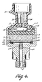
- FIGURE 4 there is shown a third embodiment of the invention wherein a constant diameter piston or transfer pin 51 is placed in the fluid inlet 5 with inlet fluid impinging on one end thereof.
- the other end of the piston is placed against a thin metal diaphragm 53 having a substantially larger surface area than either end of the piston.
- a silicon gel, elastomer or other flowable material 55 which is unaffected by the pressures involved is positioned between the diaphragm 53 and the pressure transducer layer 19 and is maintained between the diaphragm and the layer 19 by a back-up ring 59 of rigid material, such as, for example, polytetrafluoroethylene or of a non-rigid seal material.
- the pressures encountered within the package 1 are materially lower than the pressure at the package inlet, the flowable material 55 providing for uniform application of the pressure from the diaphragm 53 along the entire area thereof.
- one or more O-rings 57 are provided for the same reasons as discussed above with reference to FIGURES 2 and 3.
Landscapes
- Physics & Mathematics (AREA)
- General Physics & Mathematics (AREA)
- Electromagnetism (AREA)
- Chemical & Material Sciences (AREA)
- Engineering & Computer Science (AREA)
- Ceramic Engineering (AREA)
- Measuring Fluid Pressure (AREA)
Applications Claiming Priority (2)
| Application Number | Priority Date | Filing Date | Title |
|---|---|---|---|
| US07/366,045 US5043841A (en) | 1989-06-13 | 1989-06-13 | High pressure transducer package |
| US366045 | 1999-08-02 |
Publications (3)
| Publication Number | Publication Date |
|---|---|
| EP0403257A2 true EP0403257A2 (de) | 1990-12-19 |
| EP0403257A3 EP0403257A3 (de) | 1991-07-31 |
| EP0403257B1 EP0403257B1 (de) | 1994-03-02 |
Family
ID=23441446
Family Applications (1)
| Application Number | Title | Priority Date | Filing Date |
|---|---|---|---|
| EP90306447A Expired - Lifetime EP0403257B1 (de) | 1989-06-13 | 1990-06-13 | Hochdruckwandler |
Country Status (4)
| Country | Link |
|---|---|
| US (1) | US5043841A (de) |
| EP (1) | EP0403257B1 (de) |
| JP (1) | JPH0394132A (de) |
| DE (1) | DE69006925T2 (de) |
Cited By (4)
| Publication number | Priority date | Publication date | Assignee | Title |
|---|---|---|---|---|
| EP0757237A3 (de) * | 1995-08-01 | 1997-05-28 | Endress Hauser Gmbh Co | Druckaufnehmer |
| DE10334854A1 (de) * | 2003-07-29 | 2005-03-10 | Endress & Hauser Gmbh & Co Kg | Drucksensor |
| DE102013225335A1 (de) * | 2013-12-10 | 2014-11-13 | Siemens Aktiengesellschaft | Druckmessumformer zur Prozessinstrumentierung |
| DE102014207394B4 (de) | 2013-04-18 | 2019-05-09 | Ifm Electronic Gmbh | Drucksensor |
Families Citing this family (16)
| Publication number | Priority date | Publication date | Assignee | Title |
|---|---|---|---|---|
| JPH0640830U (ja) * | 1991-06-26 | 1994-05-31 | 応用計測工業株式会社 | 圧力計 |
| US5315877A (en) * | 1993-02-19 | 1994-05-31 | Kavlico Corporation | Low cost versatile pressure transducer |
| US5827972A (en) * | 1993-11-02 | 1998-10-27 | Texas Instruments Incorporated | High pressure sensor apparatus with low cost compact packaging system |
| US5436795A (en) * | 1994-03-28 | 1995-07-25 | Texas Instruments Incorporated | Pressure transducer apparatus and method for making same |
| US5822173A (en) * | 1996-05-29 | 1998-10-13 | Texas Instruments Incorporated | Condition responsive electrical apparatus having improved low cost housing |
| US6055864A (en) * | 1998-04-14 | 2000-05-02 | Mannesmann Vdo Ag | Pressure sensor and method for its production |
| JP3498665B2 (ja) * | 1999-03-12 | 2004-02-16 | 株式会社デンソー | 圧力検出装置およびその製造方法 |
| DE10049996A1 (de) * | 2000-10-10 | 2002-04-11 | Endress Hauser Gmbh Co | Druckmessaufnehmer |
| DE10353323A1 (de) * | 2003-11-14 | 2005-06-23 | Vega Grieshaber Kg | Sensor, insbesondere Druck-Sensor mit einer Sensoreinrichtungs-Befestigungseinrichtung |
| US7197937B2 (en) * | 2005-01-26 | 2007-04-03 | Sensata Technologies, Inc. | Hermetic pressure sensing device |
| JP4727369B2 (ja) * | 2005-09-29 | 2011-07-20 | 株式会社イトーキ | 机 |
| DE202009018862U1 (de) * | 2009-06-19 | 2014-06-04 | Peter Lischka | Autofrettage - Druckmessaufnehmer |
| DE102011077868A1 (de) * | 2011-06-21 | 2012-12-27 | Robert Bosch Gmbh | Drucksensoranordnung zur Erfassung eines Drucks eines fluiden Mediums in einem Messraum |
| JP5594541B2 (ja) * | 2012-02-09 | 2014-09-24 | Smc株式会社 | 圧力検出器 |
| DE102017119358A1 (de) * | 2017-08-24 | 2019-02-28 | Endress+Hauser SE+Co. KG | Modulares Feldgerät |
| DE102018127014A1 (de) * | 2018-10-30 | 2020-04-30 | Endress+Hauser Conducta Gmbh+Co. Kg | Prozessanschluss für einen Sensor und Herstellungsverfahren des Prozessanschlusses |
Family Cites Families (8)
| Publication number | Priority date | Publication date | Assignee | Title |
|---|---|---|---|---|
| GB1075355A (en) * | 1963-02-08 | 1967-07-12 | Fairey Eng | Improvements relating to excess pressure protective devices for pressure gauges etc |
| US4414851A (en) * | 1981-08-28 | 1983-11-15 | Motorola, Inc. | Gauge pressure sensor |
| US4425799A (en) * | 1982-06-03 | 1984-01-17 | Kavlico Corporation | Liquid capacitance pressure transducer technique |
| JPS6013235A (ja) * | 1983-07-01 | 1985-01-23 | Kinseki Kk | 圧力センサ− |
| JPS6073428A (ja) * | 1983-09-19 | 1985-04-25 | フオ−ド モ−タ− カンパニ− | 燃焼圧力センサ |
| GB2154323B (en) * | 1984-02-14 | 1987-02-18 | Plessey Co Plc | Pressure sensor |
| US4774626A (en) * | 1986-05-05 | 1988-09-27 | Texas Instruments Incorporated | Pressure sensor with improved capacitive pressure transducer |
| US4888662A (en) * | 1988-12-08 | 1989-12-19 | Texas Instruments Incorporated | High pressure package for pressure transducers |
-
1989
- 1989-06-13 US US07/366,045 patent/US5043841A/en not_active Expired - Lifetime
-
1990
- 1990-06-12 JP JP2153821A patent/JPH0394132A/ja active Pending
- 1990-06-13 DE DE69006925T patent/DE69006925T2/de not_active Expired - Fee Related
- 1990-06-13 EP EP90306447A patent/EP0403257B1/de not_active Expired - Lifetime
Cited By (4)
| Publication number | Priority date | Publication date | Assignee | Title |
|---|---|---|---|---|
| EP0757237A3 (de) * | 1995-08-01 | 1997-05-28 | Endress Hauser Gmbh Co | Druckaufnehmer |
| DE10334854A1 (de) * | 2003-07-29 | 2005-03-10 | Endress & Hauser Gmbh & Co Kg | Drucksensor |
| DE102014207394B4 (de) | 2013-04-18 | 2019-05-09 | Ifm Electronic Gmbh | Drucksensor |
| DE102013225335A1 (de) * | 2013-12-10 | 2014-11-13 | Siemens Aktiengesellschaft | Druckmessumformer zur Prozessinstrumentierung |
Also Published As
| Publication number | Publication date |
|---|---|
| EP0403257B1 (de) | 1994-03-02 |
| DE69006925T2 (de) | 1994-06-09 |
| EP0403257A3 (de) | 1991-07-31 |
| JPH0394132A (ja) | 1991-04-18 |
| US5043841A (en) | 1991-08-27 |
| DE69006925D1 (de) | 1994-04-07 |
Similar Documents
| Publication | Publication Date | Title |
|---|---|---|
| US5043841A (en) | High pressure transducer package | |
| EP0403256B1 (de) | Fertigung einer O-Ring/Staudichtung für Hochdruckwandler | |
| US4888662A (en) | High pressure package for pressure transducers | |
| US5000047A (en) | Pressure sensor | |
| US4507973A (en) | Housing for capacitive pressure sensor | |
| US5454270A (en) | Hermetically sealed pressure sensor and method thereof | |
| US6848318B2 (en) | Pressure sensor having metallic diaphragm seal joint | |
| US5060108A (en) | Packaging and sealing for pressure transducer | |
| US5001934A (en) | Solid state pressure sensor | |
| US5827972A (en) | High pressure sensor apparatus with low cost compact packaging system | |
| US8443676B2 (en) | Pressure sensor for hydraulic media in motor vehicle brake systems | |
| US4934193A (en) | Pressure sensing transmitter | |
| US6640640B2 (en) | Differential pressure sensor | |
| EP0677727A2 (de) | Druckwandler-Montage und Herstellungsverfahren dazu | |
| US6272927B1 (en) | Hermetically sealed pressure sensing device | |
| JPH02206738A (ja) | 半導体圧力検出装置 | |
| US6598482B2 (en) | Overload resistant differential pressure sensor | |
| JPH02141635A (ja) | 高圧用半導体式圧力センサの取付け構造 | |
| JPH04370726A (ja) | 半導体圧力センサ | |
| USH606H (en) | Pressure sensor assembly | |
| CN113091992B (zh) | 高量程压差传感器 | |
| JPH01248033A (ja) | 半導体式圧力センサ | |
| JPH0749282A (ja) | 圧力センサのオイルシール構造 | |
| JP3712197B2 (ja) | 圧力伝送器及び保護ブロック | |
| US20040187586A1 (en) | Low TCE fill fluid for barrier diaphragm pressure sensors |
Legal Events
| Date | Code | Title | Description |
|---|---|---|---|
| PUAI | Public reference made under article 153(3) epc to a published international application that has entered the european phase |
Free format text: ORIGINAL CODE: 0009012 |
|
| AK | Designated contracting states |
Kind code of ref document: A2 Designated state(s): DE FR GB IT NL |
|
| PUAL | Search report despatched |
Free format text: ORIGINAL CODE: 0009013 |
|
| AK | Designated contracting states |
Kind code of ref document: A3 Designated state(s): DE FR GB IT NL |
|
| 17P | Request for examination filed |
Effective date: 19911119 |
|
| 17Q | First examination report despatched |
Effective date: 19921230 |
|
| GRAA | (expected) grant |
Free format text: ORIGINAL CODE: 0009210 |
|
| ITF | It: translation for a ep patent filed | ||
| AK | Designated contracting states |
Kind code of ref document: B1 Designated state(s): DE FR GB IT NL |
|
| REF | Corresponds to: |
Ref document number: 69006925 Country of ref document: DE Date of ref document: 19940407 |
|
| ET | Fr: translation filed | ||
| PLBE | No opposition filed within time limit |
Free format text: ORIGINAL CODE: 0009261 |
|
| STAA | Information on the status of an ep patent application or granted ep patent |
Free format text: STATUS: NO OPPOSITION FILED WITHIN TIME LIMIT |
|
| 26N | No opposition filed | ||
| ITTA | It: last paid annual fee | ||
| REG | Reference to a national code |
Ref country code: GB Ref legal event code: IF02 |
|
| PGFP | Annual fee paid to national office [announced via postgrant information from national office to epo] |
Ref country code: GB Payment date: 20030501 Year of fee payment: 14 |
|
| PGFP | Annual fee paid to national office [announced via postgrant information from national office to epo] |
Ref country code: NL Payment date: 20030513 Year of fee payment: 14 |
|
| PGFP | Annual fee paid to national office [announced via postgrant information from national office to epo] |
Ref country code: FR Payment date: 20030602 Year of fee payment: 14 |
|
| PGFP | Annual fee paid to national office [announced via postgrant information from national office to epo] |
Ref country code: DE Payment date: 20030630 Year of fee payment: 14 |
|
| PG25 | Lapsed in a contracting state [announced via postgrant information from national office to epo] |
Ref country code: GB Free format text: LAPSE BECAUSE OF NON-PAYMENT OF DUE FEES Effective date: 20040613 |
|
| PG25 | Lapsed in a contracting state [announced via postgrant information from national office to epo] |
Ref country code: NL Free format text: LAPSE BECAUSE OF NON-PAYMENT OF DUE FEES Effective date: 20050101 Ref country code: DE Free format text: LAPSE BECAUSE OF NON-PAYMENT OF DUE FEES Effective date: 20050101 |
|
| GBPC | Gb: european patent ceased through non-payment of renewal fee |
Effective date: 20040613 |
|
| PG25 | Lapsed in a contracting state [announced via postgrant information from national office to epo] |
Ref country code: FR Free format text: LAPSE BECAUSE OF NON-PAYMENT OF DUE FEES Effective date: 20050228 |
|
| NLV4 | Nl: lapsed or anulled due to non-payment of the annual fee |
Effective date: 20050101 |
|
| REG | Reference to a national code |
Ref country code: FR Ref legal event code: ST |
|
| PG25 | Lapsed in a contracting state [announced via postgrant information from national office to epo] |
Ref country code: IT Free format text: LAPSE BECAUSE OF NON-PAYMENT OF DUE FEES;WARNING: LAPSES OF ITALIAN PATENTS WITH EFFECTIVE DATE BEFORE 2007 MAY HAVE OCCURRED AT ANY TIME BEFORE 2007. THE CORRECT EFFECTIVE DATE MAY BE DIFFERENT FROM THE ONE RECORDED. Effective date: 20050613 |