EP0404157A2 - Heizgerät und Heizelement - Google Patents
Heizgerät und Heizelement Download PDFInfo
- Publication number
- EP0404157A2 EP0404157A2 EP90111774A EP90111774A EP0404157A2 EP 0404157 A2 EP0404157 A2 EP 0404157A2 EP 90111774 A EP90111774 A EP 90111774A EP 90111774 A EP90111774 A EP 90111774A EP 0404157 A2 EP0404157 A2 EP 0404157A2
- Authority
- EP
- European Patent Office
- Prior art keywords
- heater
- heat
- heating apparatus
- base
- base member
- Prior art date
- Legal status (The legal status is an assumption and is not a legal conclusion. Google has not performed a legal analysis and makes no representation as to the accuracy of the status listed.)
- Granted
Links
Images


Classifications
-
- G—PHYSICS
- G03—PHOTOGRAPHY; CINEMATOGRAPHY; ANALOGOUS TECHNIQUES USING WAVES OTHER THAN OPTICAL WAVES; ELECTROGRAPHY; HOLOGRAPHY
- G03G—ELECTROGRAPHY; ELECTROPHOTOGRAPHY; MAGNETOGRAPHY
- G03G15/00—Apparatus for electrographic processes using a charge pattern
- G03G15/20—Apparatus for electrographic processes using a charge pattern for fixing, e.g. by using heat
- G03G15/2003—Apparatus for electrographic processes using a charge pattern for fixing, e.g. by using heat using heat
- G03G15/2014—Apparatus for electrographic processes using a charge pattern for fixing, e.g. by using heat using heat using contact heat
- G03G15/2053—Structural details of heat elements, e.g. structure of roller or belt, eddy current, induction heating
-
- G—PHYSICS
- G03—PHOTOGRAPHY; CINEMATOGRAPHY; ANALOGOUS TECHNIQUES USING WAVES OTHER THAN OPTICAL WAVES; ELECTROGRAPHY; HOLOGRAPHY
- G03G—ELECTROGRAPHY; ELECTROPHOTOGRAPHY; MAGNETOGRAPHY
- G03G15/00—Apparatus for electrographic processes using a charge pattern
- G03G15/06—Apparatus for electrographic processes using a charge pattern for developing
- G03G15/08—Apparatus for electrographic processes using a charge pattern for developing using a solid developer, e.g. powder developer
- G03G15/095—Removing excess solid developer, e.g. fog preventing
-
- H—ELECTRICITY
- H05—ELECTRIC TECHNIQUES NOT OTHERWISE PROVIDED FOR
- H05B—ELECTRIC HEATING; ELECTRIC LIGHT SOURCES NOT OTHERWISE PROVIDED FOR; CIRCUIT ARRANGEMENTS FOR ELECTRIC LIGHT SOURCES, IN GENERAL
- H05B3/00—Ohmic-resistance heating
- H05B3/0095—Heating devices in the form of rollers
Definitions
- the present invention relates to a heating apparatus adapted to be used with an image forming system such as an optical printer, copying machine or the like, and more particularly, it relates to a heating apparatus effectively used as a heating and fixing unit io for the image forming system, and a heater used in the heating apparatus.
- heat roller fixing systems using a heat roller having a heater such as a halogen lamp therein have widely been used as a fixing unit for fixing a toner image onto a recording medium.
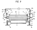
- Fig. 9 shows a sectional view of a conventional heat roller fixing unit.
- a heat roller 1 has a halogen lamp 28 therein.
- the reference numeral 2 denotes a pressure roller; 3 and 6 denote bearings; 4 denotes a drive gear for the heat roller; 5 denotes a ring for preventing the bearing 3 and the gear 4 from sliding off from the roller 1 in the thrust direction; 7 denotes a spring for biasing pressure roller 2 against the heat roller 1; 12 denotes a lead wire for supplying an electric power to the halogen heater; 13 denotes a conductive plate acting as an contact between the lead wire 12 and a power source; 14 denotes leaf springs for positioning the halogen lamp; denotes an electrode of the power source side; 20 denotes an earth spirng for earthing the heat roller 1; and 25 denotes insulating and low heat-conductive base portions made of ceramic and arranged on both sides of the halogen lamp.
- the reference numerals 13a and 14a denote biases or screws.
- the halogen lamp 28 is positioned and fixed by supporting the ceramic bases 25 of both sides of the lamp by means of the leaf springs 14 fixedly mounted on a fixed portion by the screws 14a.
- the earth ring 20 electrically connected to the fixing roller 1 is mounted on the end of the fixing roller, the operability was further worsened.
- the inner diameter of the fixing roller 1 cannot be reduced to keep the easy insertion of the lead wires 12 into the fixing roller, the fixing roller and accordingly the whole apparatus cannot be made small-sized.
- An object of the present invention is to provide a fixing unit which permits the easy replacement of a heater.
- Another object of the present invention is to provide a heating apparatus wherein a heater can easily be mounted on and dismounted from the apparatus without dismounting a holding plate for holding a heater.
- a further object of the present invention is to provide a heating apparatus wherein a heater having a larger base portion and a smaller base portion is used and the heated is inserted from its smaller base portion.
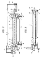
- a heat roller 1 has a halogen lamp 8 therein and is made of a metallic cylinder coated by a surface lublicant layer.
- a thermistor S is provided for detecting temperature of a surface of the heat roller 1, and the energization of the halogen lamp 8 is ON/OFF controlled on the basis of a detected output from the thermistor. In this way, the surface temperature of the heat roller 1 can be maintained in a constant value.
- a back-up roller 2 having a silicone rubber layer is pressed against the heat roller 1.
- a recording medium with a surface having a non-fixed toner image thereon (which surface faces toward the heat roller 1) is pinched between the rollers 1 and 2 and is fed by them; meanwhile, the toner image is fixed on the recording medium by the heat and pressure.
- An electrode terminal 9 projects from one end of the halogen lamp 8 in a longitudinal direction thereof and is made of deformable nickel-plated copper wire.
- the reference numeral 10 denotes contact plates tightened by a screw 10a with the interposition of the electrode terminal 9, thereby electrically connecting therebetween.
- the reference numeral 11 denotes a halogen lamp retainer for positioning and holding the halogen lamp 8 by fitting a base 18 of the lamp thereto; 16 denotes an insulation support for supporting connecting portions between the power source and the contact plates or a conductive plate 13; 17 denotes a holder for supporting the halogen lamp 8 with an aid of a leaf spring 14; 18 denotes the base of the halogen lamp at an insertion side; 19 denotes a base of the halogen lamp 8 at a side opposite to the insertion side; and denotes a conductive ring electrically connected to the fixing roller 1 and provided for earthing the fixing roller through a leaf spring (not shown) slidingly contacting with the conductive ring.
- the halogen lamp 8 is assembled in a condition that the base 19 thereof is pinched between the holder 17 and the leaf spring 14.
- a flange of the base 19 has a larger diameter than those of an opening (through which the halogen lamp is inserted) of the holder 17 and an opening of the leaf spring 14, and also larger than the diameters of the other base 18 and of a glass tube of the halogen lamp 8.
- the glass tube constituting a heat dispersing area of the lamp.
- the larger diameter means that the cross-section thereof completely includes therein the cross-section of the smaller diameter.
- the conductive ring also obstructed the passage of the base of the halogen lamp.
- the base 18 at the insertion side has the smaller diameter than that of the other base 19 and has a tapered tip, the base 18 can smoothly be inserted into the retainer 11 (Fig. 1) without being obstructed by the conductive ring 20.
- the insertion of the heater to the fixing roller and the replacement of the heater are very easy.
- the lead wire 12 is connected to the conductive plate 13 of the holder 17 as well as the halogen lamp 8 is assembled to the holder 17, when the halogen lamp 8 with the holder 17 is assembled to the fixing roller 1, the conductive plate 13 can merely be connected to the conductive portion from the power source at the insulation support 16. Thus, it is not needed to assemble by grasping the lead wire directly.
- the halogen lamp 8 when the halogen lamp 8 is inserted into the fixing roller 1 by grasping the holder, the lamp can be inserted into the roller; accordingly, since the halogen lamp is not contacted by the operator's hand, the lamp is not smeared by oil and the like. Further additionally, since the electrode terminal 9 at the insertion side has the rod-shaped configuration, the base 18 can be easily received in the retainer 11.
- the configuration of the base at the side opposite to the insertion side may have the same configuration as the base at the insertion side and may include a larger ring 25.
- one of the base is larger than the other.
- the halogen lamp may be assembled to the fixing roller by grasping it by hand, as shown in Fig. 6.
- the base at the side opposite to the insertion side may be larger than the other base to facilitate the grasping of the base.
- a lead wire 12 may be provided in place of the electrode terminal, as shown in Fig. 7.
- an electrode terminal 9 may be provided in place of the lead wire, as shown in Fig. 8.
- the assembling and the replacement of the heater become very easy, and, if the invention is applied to the heat roller fixing unit, it is possible to reduce the diameter of the heat roller.
- the present invention provides a heating apparatus comprising a heat rotary member; a heater arranged in the heat rotary member along a rotation center line thereof, which heater has low heat-conductive base members at its both ends; and a holder member for holding at least one of the base members; the one base member having an outer configuration larger than that of the other base member.
- the heater can be inserted into and removed from the heat rotary member along the rotation center line without removing the holder member from the heater.
Landscapes
- Physics & Mathematics (AREA)
- General Physics & Mathematics (AREA)
- Fixing For Electrophotography (AREA)
- Resistance Heating (AREA)
- Electric Stoves And Ranges (AREA)
- Yarns And Mechanical Finishing Of Yarns Or Ropes (AREA)
- Heating, Cooling, Or Curing Plastics Or The Like In General (AREA)
Applications Claiming Priority (2)
| Application Number | Priority Date | Filing Date | Title |
|---|---|---|---|
| JP161302/89 | 1989-06-23 | ||
| JP1161302A JP2542080B2 (ja) | 1989-06-23 | 1989-06-23 | 熱ロ―ラ定着装置 |
Publications (3)
| Publication Number | Publication Date |
|---|---|
| EP0404157A2 true EP0404157A2 (de) | 1990-12-27 |
| EP0404157A3 EP0404157A3 (de) | 1991-06-19 |
| EP0404157B1 EP0404157B1 (de) | 1994-09-07 |
Family
ID=15732528
Family Applications (1)
| Application Number | Title | Priority Date | Filing Date |
|---|---|---|---|
| EP90111774A Expired - Lifetime EP0404157B1 (de) | 1989-06-23 | 1990-06-21 | Heizgerät und Heizelement |
Country Status (9)
| Country | Link |
|---|---|
| US (1) | US5115119A (de) |
| EP (1) | EP0404157B1 (de) |
| JP (1) | JP2542080B2 (de) |
| KR (1) | KR940007963B1 (de) |
| CN (1) | CN1021934C (de) |
| DE (1) | DE69012223T2 (de) |
| ES (1) | ES2062195T3 (de) |
| FR (1) | FR2654292B1 (de) |
| IT (1) | IT1242125B (de) |
Families Citing this family (14)
| Publication number | Priority date | Publication date | Assignee | Title |
|---|---|---|---|---|
| US5223901A (en) * | 1991-04-04 | 1993-06-29 | Mita Industrial Co., Ltd. | Fixing device with temperature compensation in an image forming apparatus |
| US5221947A (en) * | 1992-02-20 | 1993-06-22 | Eastman Kodak Company | Internally heated roller assembly for toner image fixing apparatus |
| US5436431A (en) * | 1993-02-19 | 1995-07-25 | Sharp Kabushiki Kaisha | Toner image fixing device having improved lamp heater |
| US5481350A (en) * | 1993-04-12 | 1996-01-02 | Ricoh Company, Ltd. | Heat roller fixing device divided into first and second frames and with positioning members of the first frame |
| JP3245785B2 (ja) * | 1994-03-14 | 2002-01-15 | キヤノン株式会社 | コネクターおよび接続構造 |
| JP3842488B2 (ja) * | 1998-10-30 | 2006-11-08 | 株式会社リコー | 定着装置及び画像形成装置 |
| US6559421B1 (en) * | 1999-10-29 | 2003-05-06 | Ricoh Company, Ltd. | Image forming apparatus and fixing device therefor |
| JP3558161B2 (ja) * | 1999-12-16 | 2004-08-25 | ウシオ電機株式会社 | 加熱ローラ |
| US6967308B1 (en) * | 2004-05-07 | 2005-11-22 | Dell Products L.P. | System and method for information handling system peripheral heating element thermal failsafe |
| JP4651382B2 (ja) * | 2004-12-28 | 2011-03-16 | 京セラミタ株式会社 | 定着装置のヒータ取付構造 |
| JP2008052181A (ja) * | 2006-08-28 | 2008-03-06 | Brother Ind Ltd | 定着装置および画像形成装置 |
| JP2012027305A (ja) * | 2010-07-26 | 2012-02-09 | Fuji Xerox Co Ltd | 定着装置及び画像形成装置 |
| JP6919352B2 (ja) * | 2017-06-12 | 2021-08-18 | 株式会社リコー | 定着装置と画像形成装置 |
| JP2019028216A (ja) * | 2017-07-28 | 2019-02-21 | 富士ゼロックス株式会社 | 定着装置及び画像形成装置 |
Family Cites Families (14)
| Publication number | Priority date | Publication date | Assignee | Title |
|---|---|---|---|---|
| NL6407190A (de) * | 1963-07-18 | 1965-01-19 | ||
| US3437032A (en) * | 1965-07-01 | 1969-04-08 | Xerox Corp | Heated fuser roll |
| US3409280A (en) * | 1967-05-01 | 1968-11-05 | Xerox Corp | Porous drum fuser |
| US3973844A (en) * | 1974-05-28 | 1976-08-10 | Xerox Corporation | Latching mechanism for the backup roll of a roll fuser employed in a copier apparatus |
| US3946353A (en) * | 1974-12-11 | 1976-03-23 | Gallagher James G | Mounting system for infrared tubes |
| GB1525953A (en) * | 1975-01-28 | 1978-09-27 | Shell Int Research | Ball valves |
| JPS5630026A (en) * | 1979-08-20 | 1981-03-26 | Babcock Hitachi Kk | Manufacturing apparatus for heat exchanger fin |
| US4541708A (en) * | 1982-01-09 | 1985-09-17 | Canon Kabushiki Kaisha | Heating-fixing device |
| JPS6076259A (ja) * | 1983-09-30 | 1985-04-30 | Nippon Steel Corp | 溶湯流出孔閉塞部開孔方法 |
| JPS6226131A (ja) * | 1985-07-29 | 1987-02-04 | Hino Motors Ltd | 自動トランスミツシヨン |
| JPS6238673U (de) * | 1985-08-26 | 1987-03-07 | ||
| JPS6398684A (ja) * | 1986-10-16 | 1988-04-30 | Sharp Corp | 定着装置 |
| JP2909908B2 (ja) * | 1988-08-29 | 1999-06-23 | キヤノン株式会社 | 定着器 |
| US4981433A (en) * | 1988-10-15 | 1991-01-01 | Brother Kogyo Kabushiki Kaisha | Sheet heating device |
-
1989
- 1989-06-23 JP JP1161302A patent/JP2542080B2/ja not_active Expired - Fee Related
-
1990
- 1990-06-21 EP EP90111774A patent/EP0404157B1/de not_active Expired - Lifetime
- 1990-06-21 US US07/541,387 patent/US5115119A/en not_active Expired - Lifetime
- 1990-06-21 ES ES90111774T patent/ES2062195T3/es not_active Expired - Lifetime
- 1990-06-21 DE DE69012223T patent/DE69012223T2/de not_active Expired - Fee Related
- 1990-06-22 FR FR9007850A patent/FR2654292B1/fr not_active Expired - Fee Related
- 1990-06-22 IT IT48091A patent/IT1242125B/it active IP Right Grant
- 1990-06-23 CN CN90103094A patent/CN1021934C/zh not_active Expired - Fee Related
- 1990-06-23 KR KR1019900009353A patent/KR940007963B1/ko not_active Expired - Fee Related
Also Published As
| Publication number | Publication date |
|---|---|
| CN1021934C (zh) | 1993-08-25 |
| FR2654292B1 (fr) | 1993-12-24 |
| EP0404157B1 (de) | 1994-09-07 |
| JP2542080B2 (ja) | 1996-10-09 |
| CN1049233A (zh) | 1991-02-13 |
| IT9048091A0 (it) | 1990-06-22 |
| KR940007963B1 (ko) | 1994-08-31 |
| DE69012223T2 (de) | 1995-01-19 |
| EP0404157A3 (de) | 1991-06-19 |
| JPH0327074A (ja) | 1991-02-05 |
| FR2654292A1 (fr) | 1991-05-10 |
| IT1242125B (it) | 1994-02-16 |
| US5115119A (en) | 1992-05-19 |
| ES2062195T3 (es) | 1994-12-16 |
| IT9048091A1 (it) | 1991-12-22 |
| KR910001490A (ko) | 1991-01-31 |
| DE69012223D1 (de) | 1994-10-13 |
Similar Documents
| Publication | Publication Date | Title |
|---|---|---|
| US5115119A (en) | Heating apparatus and heater | |
| US4780078A (en) | Toner image thermal fixation roller | |
| US5787319A (en) | Fixing unit for use in image forming apparatus | |
| US5999789A (en) | Fixing device for an image forming apparatus | |
| JP3302825B2 (ja) | 定着装置 | |
| US4493982A (en) | Holder apparatus for heater element | |
| JPH09251253A (ja) | 静電複写画像形成装置の定着装置 | |
| JP2000150112A (ja) | 加熱ローラ | |
| JPH06258971A (ja) | 熱定着装置 | |
| JP2909908B2 (ja) | 定着器 | |
| JPH09265246A (ja) | 定着装置 | |
| JP3809745B2 (ja) | 定着装置 | |
| JPH04316073A (ja) | 熱ローラ定着装置及びヒータ | |
| JP3731363B2 (ja) | 定着装置 | |
| JPH0226143Y2 (de) | ||
| JPH09134088A (ja) | 加熱定着ローラ | |
| JPH08254916A (ja) | 加熱定着装置 | |
| JPH08328415A (ja) | ヒータロール | |
| JP2001154522A (ja) | 定着装置のヒータ支持装置 | |
| JPH0968879A (ja) | 熱定着装置および画像形成装置 | |
| JP3642387B2 (ja) | 定着装置及び画像形成装置 | |
| JPH0756461A (ja) | 温度検出体 | |
| JP2000194221A (ja) | 加熱定着装置 | |
| JPS62202481A (ja) | 電気的接続装置 | |
| JPH08314306A (ja) | 定着装置 |
Legal Events
| Date | Code | Title | Description |
|---|---|---|---|
| PUAI | Public reference made under article 153(3) epc to a published international application that has entered the european phase |
Free format text: ORIGINAL CODE: 0009012 |
|
| AK | Designated contracting states |
Kind code of ref document: A2 Designated state(s): DE ES GB |
|
| 17P | Request for examination filed |
Effective date: 19901221 |
|
| PUAL | Search report despatched |
Free format text: ORIGINAL CODE: 0009013 |
|
| AK | Designated contracting states |
Kind code of ref document: A3 Designated state(s): DE ES GB |
|
| 17Q | First examination report despatched |
Effective date: 19921013 |
|
| GRAA | (expected) grant |
Free format text: ORIGINAL CODE: 0009210 |
|
| AK | Designated contracting states |
Kind code of ref document: B1 Designated state(s): DE ES GB |
|
| REF | Corresponds to: |
Ref document number: 69012223 Country of ref document: DE Date of ref document: 19941013 |
|
| REG | Reference to a national code |
Ref country code: ES Ref legal event code: FG2A Ref document number: 2062195 Country of ref document: ES Kind code of ref document: T3 |
|
| PLBE | No opposition filed within time limit |
Free format text: ORIGINAL CODE: 0009261 |
|
| STAA | Information on the status of an ep patent application or granted ep patent |
Free format text: STATUS: NO OPPOSITION FILED WITHIN TIME LIMIT |
|
| 26N | No opposition filed | ||
| REG | Reference to a national code |
Ref country code: GB Ref legal event code: IF02 |
|
| PGFP | Annual fee paid to national office [announced via postgrant information from national office to epo] |
Ref country code: DE Payment date: 20060615 Year of fee payment: 17 |
|
| PGFP | Annual fee paid to national office [announced via postgrant information from national office to epo] |
Ref country code: GB Payment date: 20060621 Year of fee payment: 17 |
|
| PGFP | Annual fee paid to national office [announced via postgrant information from national office to epo] |
Ref country code: ES Payment date: 20060626 Year of fee payment: 17 |
|
| GBPC | Gb: european patent ceased through non-payment of renewal fee |
Effective date: 20070621 |
|
| PG25 | Lapsed in a contracting state [announced via postgrant information from national office to epo] |
Ref country code: DE Free format text: LAPSE BECAUSE OF NON-PAYMENT OF DUE FEES Effective date: 20080101 |
|
| PG25 | Lapsed in a contracting state [announced via postgrant information from national office to epo] |
Ref country code: GB Free format text: LAPSE BECAUSE OF NON-PAYMENT OF DUE FEES Effective date: 20070621 |
|
| REG | Reference to a national code |
Ref country code: ES Ref legal event code: FD2A Effective date: 20070622 |
|
| PG25 | Lapsed in a contracting state [announced via postgrant information from national office to epo] |
Ref country code: ES Free format text: LAPSE BECAUSE OF NON-PAYMENT OF DUE FEES Effective date: 20070622 |