EP0924376A2 - Palier externe pour vantail basculant - Google Patents
Palier externe pour vantail basculant Download PDFInfo
- Publication number
- EP0924376A2 EP0924376A2 EP98124141A EP98124141A EP0924376A2 EP 0924376 A2 EP0924376 A2 EP 0924376A2 EP 98124141 A EP98124141 A EP 98124141A EP 98124141 A EP98124141 A EP 98124141A EP 0924376 A2 EP0924376 A2 EP 0924376A2
- Authority
- EP
- European Patent Office
- Prior art keywords
- wing
- frame
- bearing
- axis
- sash
- Prior art date
- Legal status (The legal status is an assumption and is not a legal conclusion. Google has not performed a legal analysis and makes no representation as to the accuracy of the status listed.)
- Granted
Links
- 238000000034 method Methods 0.000 claims abstract description 4
- 238000010276 construction Methods 0.000 claims description 26
- 238000003780 insertion Methods 0.000 claims description 4
- 230000037431 insertion Effects 0.000 claims description 4
- 125000006850 spacer group Chemical group 0.000 claims description 4
- 241000596926 Sparaxis Species 0.000 claims 1
- 238000007789 sealing Methods 0.000 description 15
- 230000002441 reversible effect Effects 0.000 description 8
- 230000008859 change Effects 0.000 description 6
- 238000013461 design Methods 0.000 description 4
- 235000015095 lager Nutrition 0.000 description 4
- 230000008878 coupling Effects 0.000 description 3
- 238000010168 coupling process Methods 0.000 description 3
- 238000005859 coupling reaction Methods 0.000 description 3
- 230000000903 blocking effect Effects 0.000 description 2
- 238000006073 displacement reaction Methods 0.000 description 2
- 238000005516 engineering process Methods 0.000 description 2
- 230000007246 mechanism Effects 0.000 description 2
- 241001295925 Gegenes Species 0.000 description 1
- 230000009471 action Effects 0.000 description 1
- 230000006978 adaptation Effects 0.000 description 1
- 230000004323 axial length Effects 0.000 description 1
- 230000015572 biosynthetic process Effects 0.000 description 1
- 230000006835 compression Effects 0.000 description 1
- 238000007906 compression Methods 0.000 description 1
- 238000013016 damping Methods 0.000 description 1
- 239000006260 foam Substances 0.000 description 1
- 210000001061 forehead Anatomy 0.000 description 1
- 238000009434 installation Methods 0.000 description 1
- 239000002655 kraft paper Substances 0.000 description 1
- 238000004519 manufacturing process Methods 0.000 description 1
- 239000000463 material Substances 0.000 description 1
- 230000010355 oscillation Effects 0.000 description 1
- 238000000926 separation method Methods 0.000 description 1
- 238000012549 training Methods 0.000 description 1
- 238000012546 transfer Methods 0.000 description 1
- 238000009423 ventilation Methods 0.000 description 1
Images


Classifications
-
- E—FIXED CONSTRUCTIONS
- E05—LOCKS; KEYS; WINDOW OR DOOR FITTINGS; SAFES
- E05D—HINGES OR SUSPENSION DEVICES FOR DOORS, WINDOWS OR WINGS
- E05D11/00—Additional features or accessories of hinges
- E05D11/10—Devices for preventing movement between relatively-movable hinge parts
- E05D11/1028—Devices for preventing movement between relatively-movable hinge parts for maintaining the hinge in two or more positions, e.g. intermediate or fully open
- E05D11/1078—Devices for preventing movement between relatively-movable hinge parts for maintaining the hinge in two or more positions, e.g. intermediate or fully open the maintaining means acting parallel to the pivot
-
- E—FIXED CONSTRUCTIONS
- E05—LOCKS; KEYS; WINDOW OR DOOR FITTINGS; SAFES
- E05D—HINGES OR SUSPENSION DEVICES FOR DOORS, WINDOWS OR WINGS
- E05D7/00—Hinges or pivots of special construction
- E05D7/08—Hinges or pivots of special construction for use in suspensions comprising two spigots placed at opposite edges of the wing, especially at the top and the bottom, e.g. trunnions
- E05D7/082—Hinges or pivots of special construction for use in suspensions comprising two spigots placed at opposite edges of the wing, especially at the top and the bottom, e.g. trunnions the pivot axis of the wing being situated at a considerable distance from the edges of the wing, e.g. for balanced wings
- E05D7/083—Hinges or pivots of special construction for use in suspensions comprising two spigots placed at opposite edges of the wing, especially at the top and the bottom, e.g. trunnions the pivot axis of the wing being situated at a considerable distance from the edges of the wing, e.g. for balanced wings with a fixed pivot axis
-
- E—FIXED CONSTRUCTIONS
- E05—LOCKS; KEYS; WINDOW OR DOOR FITTINGS; SAFES
- E05D—HINGES OR SUSPENSION DEVICES FOR DOORS, WINDOWS OR WINGS
- E05D11/00—Additional features or accessories of hinges
- E05D11/10—Devices for preventing movement between relatively-movable hinge parts
- E05D11/1007—Devices for preventing movement between relatively-movable hinge parts with positive locking
-
- E—FIXED CONSTRUCTIONS
- E05—LOCKS; KEYS; WINDOW OR DOOR FITTINGS; SAFES
- E05Y—INDEXING SCHEME ASSOCIATED WITH SUBCLASSES E05D AND E05F, RELATING TO CONSTRUCTION ELEMENTS, ELECTRIC CONTROL, POWER SUPPLY, POWER SIGNAL OR TRANSMISSION, USER INTERFACES, MOUNTING OR COUPLING, DETAILS, ACCESSORIES, AUXILIARY OPERATIONS NOT OTHERWISE PROVIDED FOR, APPLICATION THEREOF
- E05Y2900/00—Application of doors, windows, wings or fittings thereof
- E05Y2900/10—Application of doors, windows, wings or fittings thereof for buildings or parts thereof
- E05Y2900/13—Type of wing
- E05Y2900/148—Windows
Definitions
- the invention relates to a fitting (storage) for about one middle axis rotatable and mounted on a frame.
- Such wings can be swing wings or reversible wings where the swing axis or Turning axis runs horizontally or vertically.
- One for such a wing or Reversible wing suitable bearing includes a left and right or an upper and lower wing bearing part on one side and on the other side on the spar of the Sash or frame. These two bearings can be configured the same.
- the invention has set itself the task of creating a uniform swing bearing or swivel bearing for a wide variety of types of profiles, in particular interchangeable profiles, and system designs of sashes and frame and for a wide variety of dimensions, which can therefore perform its intended function regardless of its location.
- the oscillation axis or turning axis no longer runs in the area of the wing or in the area of the window frame, but above the rollover, which in the area of the respective bearing of the wing is also pivoted by a Wing outward rollover ("wing rollover”) in a not pivoted and the rollover that remains firmly on the frame and starts from it (“Frame overlap”) changes, the full extent in the closed state run.
- wing rollover Wing outward rollover
- the rollovers mentioned are based on the change profile.
- a cushioning layer made of foam can be arranged on the blunt abutting location be the sealing function.
- the butt-jointed ends of the fixed flap and the the wing flap is tailored so that in the closed State the cut edges lie on each other and in the open state the two straight (blunt) ends form a plane in which the Swing axis of the wing - or the turning axis - runs.
- a change in the sealing level takes place in the area of the bearing, in each case formed through two circumferential sealing lips.
- the two further out Sealing lips are completely continuous in the outward-facing Rollovers in their respectively closely adjacent one another Marginal areas.
- An alternating profile runs on both sides of the camp, the part of the frame on this side, part of the wing beyond and in each case is firmly attached there.
- the respective interchangeable profile, half around the The wing and half around the frame runs on one of each Put sealing lips on and conceal them.
- Claim 1 describes a camp with two mounting pieces, one wing-side and a frame piece on the frame side, which is used to shift the axis of rotation (the Swing or turning axis of a swing wing or turning wing) from the Frame and sash out, or from the respective spar of the respective Frame out, serve. A distance is created with them, the axis of rotation (Swing axis or turning axis) from the respective spar, so that the Construction pieces can also be called spacers, cf. the related description of the wing in claim 2.
- two bearings are used for a swing wing or reversible wing, either a left and a right bearing for a swing wing or an upper and a lower bearing for a reversible wing.
- the axis of rotation is significantly outside of Level of the wing and the plane of the window frame positioned.
- the axis runs above the rollovers and therefore in the room and no longer through the material of the Frame or wing or the interchangeable profile.
- a shift of the swivel axis enables the change of profile in the Storage area so that a blunt bump occurs in the closed position.
- the completely closed position is the end of the alternating profile of the frame blunt on the end of the alternating profile of the wing, which last matches the Movement of the wing moves.
- the fully open position i.e. in one Position in which the window frame is pivoted by 180 ° and the upper wing area the two lie parallel to the lower frame area blunt ends in a flat plane, including the axis of rotation of the wing runs.
- the plane in question runs horizontal; if the wing is reversible, the plane in question runs vertical and the upper and lower areas of the wing described above then the right and left areas or left and right areas, depending on Opening direction of the wing.
- a closing torque is created that moves the wing in the closed position holds.
- This closing force corresponds to the lever arm between the vertical center plane of the wing and the swing axis formed here Axis of rotation. In combination with the weight of the wing, this results in an effective one Closing torque when the sash is installed.
- a compensation force can be applied (claim 15) is effective at least on one bearing, but is preferably provided on both bearings can be. This compensation force works against the closing torque, compensates for it and can even overcompensate to open it Swing wing already exert a slight torque in the opening direction and to make it easier for the user to open the wing at first (Claim 16).
- This closing torque can be overridden for assembly (Claim 16).
- the compensation force can be a prestressed Spring are applied (claim 18) in the wing-side construction piece in a spring receiving space is arranged (claim 19, 18).
- a across Extension of the wing construction piece oriented latch bolt engages from that Cover frame mounting piece or the intermediate bearing axle holding piece over to the inside of the wing construction piece, in there into a recess intervene and specify a locking position blocking the rotary movement.
- the Engagement opening can be the extension of the spring receiving space, so that directly when engaging the bolt nose the compensation force on the engaging Locking bolt can be applied perpendicular to the orientation of the axis.
- the position of the spring receiving space is preferably slightly inclined relative to the Center plane through the bearing axis bolt, which center plane is also vertical runs to the closed wing on which the construction piece is arranged.
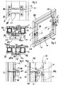
- FIG. 5 illustrates in side view the insertion of a laterally protruding bearing 40, which can be a bolt. It is directed laterally outwards and runs parallel to the plane of the wing.
- the pivot axis 100 which can also be a turning axis in a vertical arrangement, is fixed on each side of the casement.
- the extension of the bolts does not go beyond the lateral extension of the flap U1 of the wing in FIG. 1 , they are rather designed to extend so far in this direction that they can be accommodated in a receiving groove 31 within the elongated bearing piece receptacle 30, which can be received by the Frame part 10 protrudes laterally and also reaches over the sash flap.
- the wing can thus be inserted from above with its laterally extending bearing bolts 40 into the receiving troughs 31, which can then be covered 32.
- the long oval bearing piece holder 30 (the lower bearing cover) forms with the Frame-side construction piece 10 has an L-shaped shape, the short leg the mounting piece and the longer leg the bearing receptacle for the bearing pin 40 of the wing.
- FIGS. 3 and 4 the course of the interchangeable profile WP0, WP1 is shown in two sectional views, one above and one below the bearing with the two attachment pieces 10, 20 and the intermediate flat oval bearing shell 30.
- the interchangeable profile WP1 is attached to wing F. It moves with the sash when opening inwards / downwards in Figure 1 .
- a guide groove N1 is formed which receives a drive rod; with it, locking via the operating handle G is possible.
- the drive rod runs in the groove N1 in the upper half of the wing under the interchangeable profile, that is, between the end face of the sash F and the interchangeable profile WP1.
- the seal D3 in Figures 3 and 4 is ineffective for the operational sequence (movement of the wing), instead the two sealing strips D2 and D1 seal the interchangeable profile with respect to the frame BR in the closed state.
- the groove N1 from FIG. 3 leads into the groove N1 of FIG. 4 , which receives the same drive rod without cranking and without an offset intermediate piece, in order to guide it on the lower half of the wing F and to connect it to the actuating handle G functionally.
- the interchangeable profile WP0 is arranged in a fixed manner in FIG. 4 on the frame side BR, so it does not move with the movement of the wing F and the seals in the course of operation take over the sealing strips D2 and D1 here, which seal against the sealing strips D2 / in FIG. D1 laterally offset, but equally spaced in the direction perpendicular to the wing plane.
- the groove N0 that points away from the frame in FIG. 4 and points towards the frame in FIG. 3 does not accommodate a connecting rod in those areas that are drawn vertically in FIG. 1, that is to say those spars of the frame and wings that originate from the storage area.
- the drive rod guided in N1 breaks through the exchangeable profile through suitable openings, and with a deflection the linkage is then placed in the upper area in the groove N0 (not shown) pointing outwards there according to FIG. 3 and guided there in order to be able to provide locking lugs.
- the groove N0 pointing to the wing F is suitable as a continuation from FIG. 4 after the corner region, e.g. B. record locking plates in order to offer locking possibilities with respect to the drive rod which is still guided in the groove N1 of the wing if the locking plates are juxtaposed with certain projections which are actuated via the drive rod.
- the blunt stop at the level of the axis 100 which is shown in FIGS. 5 and 6 at 101 as a plane which runs perpendicular to the plane of the window frame of FIG. 1, allows a simple change of the sealing plane and a simple adaptation of the change profile to the Casement or frame.
- the height of the construction pieces 10, 20 is of the same height on both sides of the wing, which can be seen from FIG. 6 , which shows the opened state of the wing F relative to the frame BR.
- the blunt ends of the alternating profile of the sash and frame meet and can be sealed by a damping layer 25 in the closed state.
- the distance d of the axis 100 from the surface of the window frame or sash in the closed state is most clearly visible in FIG. 3 in section. This distance d is chosen so that the axis 100 is just next to the wing flap so that the long oval receptacle 30 still fits halfway between the axis and the surface of the flap U1.
- the flat oval bearing shell 30 in FIG. 2 consists of a jacket which protrudes from the mounting piece 10 projecting from the frame BR in the direction parallel to the plane of the frame.
- the flat oval shape is visually appealing, but not absolutely necessary for the function. When installed, it lies freely visible above the flap and hides the blunt separation area of the interchangeable profile. When assembled, each bearing acts as if it overlaps the interchangeable profile with a rollover and is fixedly arranged on both sides in the rollover, once on the frame and once on the casement. The entire area of the interchangeable profile visible from the handle side is thus bridged.
- Figure 7 illustrates a partial section through the U-shaped bearing frame, which is shown in supervision in Figure 2 and perspective in Figure 1 (left bearing).
- the former is the axis of rotation which runs through the bearing pin 40, which is fixed with its hat-shaped end 40a in the Construction piece 20 is arranged on the frame and rests on the bottom of a receptacle 31 which is open from above and can be rotated there, in accordance with the pivoting movement or the turning movement of the wing F.
- the rotational movement is denoted by w.
- the receiving region 31 which is matched in length to the length of the bearing pin 40 is covered by a cover 32 which is matched to the upper end of the central part 30 of the bearing.
- a collar 41 is provided approximately in the middle of the bearing pin 40, which can be seen better in FIG. 9 in a view in the direction of the axis 100.
- the collar 41 engages in the cover 32 and through the bottom of the Receiving area 31 into an elongated bore 51 which through the Middle part 30 of the camp runs. It stands slightly in this hole and points spaced locking recesses 42a, 42b, 42c circumferentially, into which the collar 53 one Pin 50 can grip when it is by a spring 52 which is in the blind hole End of the bore 51 is biased so that the collar 41 just from that Collar 53 is blocked in its pivoting movement.
- the collar 53 of the long, however thin pin 50 is very small compared to the collar 41 on the much stronger Bolt 40, preferably less than a third of the diameter.
- FIG. 8 an alternative locking option is shown, in which the pin 50 runs continuously in the bore 51 and does not block the collar 41 on the bearing pin 40, instead it has a front locking lug 49, which can engage in the flat side of the wing mounting piece 20 and can interlock there in circular locking recesses 48a or depressions, as the enlarged detail AV shows.
- the pin 50 is resiliently biased in the other direction, and pulling the pin 51 out releases the wing, while in FIG. 7 pushing the pin 50 in releases the wing pivoting movement.
- the two movements are called axial movements ⁇ P to fix the swivel position.
- the control from the frame side is advantageous because it is independent of the Rotational position of the wing is always possible in the same place.
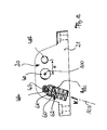
- FIG. 10 illustrates a perspective illustration of a wing-side structural part 21, 20, as can largely be seen from FIG. 2.
- FIG. 10 shows the construction piece 10, 11 on the frame side and a cover or receptacle 30 arranged therebetween, which is essentially long oval, here with a more clearly defined round area and a short rectangular area adjoining it and one to the wing and Frame flattened area, as can be seen in the sectional view of Figure 11 .
- This essentially flat oval design enables the insertion of the bearing axle piece 40, which is fixedly (non-rotatably) arranged in the mounting piece 20 on the frame side and engages in a corresponding pivot bearing of the receptacle 30, which in turn is fixedly arranged on the frame piece 10.
- FIG. 10 The internal structure of the bearing according to FIG. 10 is from the sectional views of FIG. 11 and 8 can also be seen, as seen from the inside of the wing Building piece 20, which side is hidden in Figure 10.
- a cross bolt 49 is pin-shaped, which has a handle portion 50a at its actuating end, corresponding to the protruding pin 50 from FIG. 7, only here as an elongated web with an orientation like the construction piece 10, visible in its two axial positions in the enlarged detail AV.
- the crossbar is offset in relation to the axis 100 in the respective bearing and allows the turning or swinging movement of the wing to be blocked, which can be released by means of aids or by hand via the handle section 50a.
- the cross bar 49 is pretensioned in the form of a pin and spring-loaded for engagement in one or more recesses 48b, 48a which are arranged on the wing side 20 around the bearing pin 40.
- the grip section 50a is to be grasped and actuated (to the right / back in FIG. 10) so that the locking is released, that is to say the engagement of the pin 49 in the locking recess 48a.
- a further locking position can be provided with the locking recess 48b, which has such a position that it is offset somewhat less than 180 ° with respect to the first locking recess.
- This locking trough defines the complete open position of the reversible sash, while the first locking trough 48a is arranged such that it defines a first rotational position of the wing at a slight angle of 15 ° to 20 ° with respect to the open position.
- the aforementioned first rotational position can be spring-loaded to Applying a compensation torque to the wing by its shifted axis of rotation 40, which is outside the profile of the frame or Wing spar runs, experiences a closing torque leading to the closed position.
- This caused the offset of the axis of rotation by the weight of the wing Closing torque is compensated for by the spring force of a spring 60 on the described locking bolt 49, which in the recess 48a on the wing side Construction piece engages. If he is released from it, there is no transfer of one Force component more instead, the wing can then be operated freely and in the order Snap the 180 ° swiveled position into the bolt recess 48b again.
- a longitudinal recess slightly inclined in its orientation 103 accommodates a spring 60 which is biased in the space 48c via a coupling piece 61 located at the top.
- the space 48c merges directly into the locking recess 48a described, but is somewhat wider, so that the coupling piece 61 experiences a stop and, despite pretensioning the spring 60, the locking bolt can engage in the extension of the spring receiving space 48c.
- the coupling thus created via the intermediate piece 61 now leads to an additional compression of the spring 60, which is able to apply a torque with respect to the axis 100 of the bearing axle piece 40, when the wing-side mounting piece 20 rotates relative to the frame part 10.
- the entire spring chamber 62 which consists of the lower region 48c and the upper Area 48a forms, is designed to be wider at the bottom than at the top and approximately has one at the top cylindrical shape, for receiving the locking bolt 49.
- the compensation force can be determined by the distance of the axis 103 from the axis 100 can also be set by selecting the Spring constants of the cylinder spring 60. This spring is advantageously interchangeable to different wing weights can be set.
- This first rotary position of the wing can be a security position or a ventilation position, which can additionally be secured by locking the transversely oriented locking bolt 49 or 50 with its actuating section 50a by means of a screw 50b which is difficult to access or a hexagon socket screw which is not used by unauthorized persons or is difficult to solve.
- the hard-to-access screw 50b is in the detail enlargement AV of the in Figure 10 right assembly piece 10 shown.
- This construction piece is in his Handle side of the wing of Figure 1 showing the upper surface area with a provided approximately square recess 50c, which deep into the web portion 10th reaches in.
- the hexagon socket screw difficult-to-access screw 50b shown is partially from the Handle section 50a of the bolt is covered with its locking nose 49.
- the handle 50a is shown in two axial positions, the locking position (left) and the unlocked position (dashed). In the latch position, the overlaps approximately rectangular handle portion 50a, guided in the aforementioned recess 50c Partially screw 50b.
- the angular position according to FIG. 11 can also be oriented such that it achieves a balancing of the wing.
- This balance position results from the fact that the opening torque and the torque tending to close are both essentially the same size, so that the first rotational position at an angle ⁇ only by locking the locking bolt 49 or the front nose of the locking bolt with the rear handle 50a leads to a determination, but is not energetically loaded in either direction.
- an approximately equilibrium of the torques is thus achieved, from which the locking on the handle 50a can be released without the risk of immediate pivoting, in order to either completely close the wing from the first rotational position ⁇ or to open it further.
- each wing-side construction piece 21, 20 This bearing receptacle is designed like an elongated hole, so that from above or diagonally above in the case of a horizontal Axis of rotation of a swing wing of the wing with the protruding bearing bolts in the Bearing is used in the receptacle 30 when the cover 32 is removed.
- a tongue protruding obliquely upwards or a finger provided slot-like at least in the front section defines a receptacle for Insert the respective bearing bolt of the wing-side construction piece 20.
- the diagonally upwardly projecting Tongue is spaced, absorbs transverse forces and corresponds to one in the groove in the bearing pin. In this way there is a rotational movement possible with a bearing secured in the direction of the bolt.
- the invention has set itself the task of various types of profiles, in particular interchangeable profiles, and system designs of wings and A frame and a uniform swing bearing for various dimensions or to create a reversible bearing that is independent of its location can perform the intended function.
- Storage for is proposed each a spar of a wing (F), the pivot axis (100) near the middle
- the area of the wing spar runs for mounting on two opposite spars of the wing and a frame.
- two construction pieces (10, 11; 20, 21) one Distance (d) to the frame (BR) and the wing (F) specified so that the The axis of rotation (100) runs next to the plane of the wing (F).
- the Construction pieces (10, 11; 20, 21) are used to create the distance (d) from the axis of rotation (100) from the plane of the wing to the surface. Installation on the frame (BR) and on Adjusted wing (F).
Landscapes
- Engineering & Computer Science (AREA)
- Mechanical Engineering (AREA)
- Hinges (AREA)
- Closing And Opening Devices For Wings, And Checks For Wings (AREA)
- Wing Frames And Configurations (AREA)
- Support Of The Bearing (AREA)
Applications Claiming Priority (4)
| Application Number | Priority Date | Filing Date | Title |
|---|---|---|---|
| DE19756521 | 1997-12-18 | ||
| DE19756521 | 1997-12-18 | ||
| DE19846216 | 1998-10-07 | ||
| DE19846216 | 1998-10-07 |
Publications (3)
| Publication Number | Publication Date |
|---|---|
| EP0924376A2 true EP0924376A2 (fr) | 1999-06-23 |
| EP0924376A3 EP0924376A3 (fr) | 2002-07-17 |
| EP0924376B1 EP0924376B1 (fr) | 2005-11-23 |
Family
ID=26042609
Family Applications (1)
| Application Number | Title | Priority Date | Filing Date |
|---|---|---|---|
| EP98124141A Expired - Lifetime EP0924376B1 (fr) | 1997-12-18 | 1998-12-18 | Palier externe pour vantail basculant |
Country Status (3)
| Country | Link |
|---|---|
| EP (1) | EP0924376B1 (fr) |
| AT (1) | ATE310880T1 (fr) |
| DE (2) | DE19857650A1 (fr) |
Cited By (2)
| Publication number | Priority date | Publication date | Assignee | Title |
|---|---|---|---|---|
| CN109552602A (zh) * | 2018-12-24 | 2019-04-02 | 深圳市道通智能航空技术有限公司 | 一种无人飞行器 |
| EP3045648B1 (fr) * | 2015-01-15 | 2021-05-05 | SCHÜCO International KG | Plein de fenetre basculante dote d'un systeme d'etancheification |
Family Cites Families (8)
| Publication number | Priority date | Publication date | Assignee | Title |
|---|---|---|---|---|
| US1364312A (en) * | 1916-11-02 | 1921-01-04 | Francis J Plym | Interlocking molding for pivoted or swinging frames |
| GB1086948A (en) * | 1963-09-10 | 1967-10-11 | Automatic Pressings Ltd | Improvements in and relating to hinges |
| GB1079354A (en) * | 1965-05-06 | 1967-08-16 | Crompton Nettlefold Stenman | Limited movement safety hinge for windows and the like |
| DE2448226A1 (de) * | 1974-10-09 | 1976-04-22 | Hoeganaes Ab | Rauchabzug-verschlussklappe |
| FR2372948A1 (fr) * | 1976-12-03 | 1978-06-30 | Salvado Cugat Jose | Perfectionnements apportes aux baies pivotantes |
| GB8803571D0 (en) * | 1988-02-16 | 1988-03-16 | Magnet Plc | Emergency window system |
| DE3935521A1 (de) * | 1989-10-25 | 1991-05-02 | Hautau Gmbh W | Schwingfluegellager-baureihe |
| DE29813095U1 (de) * | 1998-07-23 | 1998-11-26 | Gretsch-Unitas GmbH Baubeschläge, 71254 Ditzingen | Schwing- oder Wendeflügel eines Fensters |
-
1998
- 1998-12-14 DE DE19857650A patent/DE19857650A1/de not_active Withdrawn
- 1998-12-18 DE DE59813217T patent/DE59813217D1/de not_active Expired - Lifetime
- 1998-12-18 AT AT98124141T patent/ATE310880T1/de not_active IP Right Cessation
- 1998-12-18 EP EP98124141A patent/EP0924376B1/fr not_active Expired - Lifetime
Non-Patent Citations (1)
| Title |
|---|
| None |
Cited By (2)
| Publication number | Priority date | Publication date | Assignee | Title |
|---|---|---|---|---|
| EP3045648B1 (fr) * | 2015-01-15 | 2021-05-05 | SCHÜCO International KG | Plein de fenetre basculante dote d'un systeme d'etancheification |
| CN109552602A (zh) * | 2018-12-24 | 2019-04-02 | 深圳市道通智能航空技术有限公司 | 一种无人飞行器 |
Also Published As
| Publication number | Publication date |
|---|---|
| EP0924376B1 (fr) | 2005-11-23 |
| DE19857650A1 (de) | 1999-06-24 |
| ATE310880T1 (de) | 2005-12-15 |
| EP0924376A3 (fr) | 2002-07-17 |
| DE59813217D1 (de) | 2005-12-29 |
Similar Documents
| Publication | Publication Date | Title |
|---|---|---|
| DE2920581C3 (de) | Zusatzverriegelung, insbesondere Mittelverriegelung, für Fenster, Türen od.dgl. | |
| EP0356728B1 (fr) | Dispositif de commande de la séquence de fermeture de portes à doubles battants | |
| EP0460620B1 (fr) | Charnière pour porte | |
| EP0977930B1 (fr) | Armature avec bras de suspension ou bras de projection pour le placement d'un chassis tournant ou d'un chassis oscillant-basculant de fenetre | |
| CH624729A5 (fr) | ||
| EP0936332A2 (fr) | Serrure de porte pour véhicule | |
| DE2803346A1 (de) | Verriegelungsvorrichtung fuer eine tuere | |
| EP0330192A2 (fr) | Store à rouleau pour la fermeture d'ouvertures | |
| EP0119434A2 (fr) | Panneau de fenêtre, de porte ou similaire pouvant se déplacer hors de son plan, au moins dans sa partie inférieure | |
| DE4201070A1 (de) | Getriebe fuer ein tuerschloss, insbesondere ein panik- oder rauchschutztuerschloss | |
| DE3844627A1 (de) | Mit verschlussmitteln ausgeruestetes fenster, tuer oder dergleichen | |
| EP0844348B1 (fr) | Penture pour portes ou fenêtres | |
| EP1223287B1 (fr) | Dispositif de retenue à montage simple avec fonctions additionnelles | |
| DE29601966U1 (de) | Zusatzschloß für Flügel von Türen, Fenstern o.dgl. | |
| EP0924376B1 (fr) | Palier externe pour vantail basculant | |
| EP0980951B1 (fr) | Ferrure pour fenêtres, portes ou analogues pouvant être déplacés selon un plan parallèle et par la suite être coulissés. | |
| DE69402465T2 (de) | Fensterrahmen mit Betätigungsvorrichtung für Riegelstangenverschlüsse | |
| EP3613929B1 (fr) | Ferrure destinée à être installée entre un battant et un cadre fixe de fenêtre, porte ou analogue ainsi que fenêtre, porte ou analogue dotée d'une telle ferrure | |
| DE19718325C1 (de) | Selbsttätig wirkende Justiervorrichtung | |
| AT394607B (de) | Mehrfachverriegelung | |
| DE3901998A1 (de) | Eckverriegelungseinrichtung fuer fenster oder tueren | |
| DE4403524A1 (de) | Anordnung eines Ecklagers an einem Fenster oder einer Tür sowie für diese Anordnung bestimmtes Ecklager | |
| DE2443036A1 (de) | Ausstellvorrichtung | |
| EP4335997B1 (fr) | Module de fermeture pour une porte et porte dotée d'un module de fermeture | |
| EP0982456A2 (fr) | Porte basculante à panneau unique avec dispositif d'équilibrage utilisant un mécanisme de levier |
Legal Events
| Date | Code | Title | Description |
|---|---|---|---|
| PUAI | Public reference made under article 153(3) epc to a published international application that has entered the european phase |
Free format text: ORIGINAL CODE: 0009012 |
|
| AK | Designated contracting states |
Kind code of ref document: A2 Designated state(s): AT BE CH CY DE DK ES FI FR GB GR IE IT LI LU MC NL PT SE |
|
| AX | Request for extension of the european patent |
Free format text: AL;LT;LV;MK;RO;SI |
|
| PUAL | Search report despatched |
Free format text: ORIGINAL CODE: 0009013 |
|
| AK | Designated contracting states |
Kind code of ref document: A3 Designated state(s): AT BE CH CY DE DK ES FI FR GB GR IE IT LI LU MC NL PT SE |
|
| AX | Request for extension of the european patent |
Free format text: AL;LT;LV;MK;RO;SI |
|
| 17P | Request for examination filed |
Effective date: 20021218 |
|
| AKX | Designation fees paid |
Designated state(s): AT BE CH DE FR GB IT LI |
|
| 17Q | First examination report despatched |
Effective date: 20030703 |
|
| GRAP | Despatch of communication of intention to grant a patent |
Free format text: ORIGINAL CODE: EPIDOSNIGR1 |
|
| RIN1 | Information on inventor provided before grant (corrected) |
Inventor name: LAHMANN, ERNST |
|
| GRAS | Grant fee paid |
Free format text: ORIGINAL CODE: EPIDOSNIGR3 |
|
| GRAA | (expected) grant |
Free format text: ORIGINAL CODE: 0009210 |
|
| AK | Designated contracting states |
Kind code of ref document: B1 Designated state(s): AT BE CH DE FR GB IT LI |
|
| PG25 | Lapsed in a contracting state [announced via postgrant information from national office to epo] |
Ref country code: IT Free format text: LAPSE BECAUSE OF FAILURE TO SUBMIT A TRANSLATION OF THE DESCRIPTION OR TO PAY THE FEE WITHIN THE PRESCRIBED TIME-LIMIT;WARNING: LAPSES OF ITALIAN PATENTS WITH EFFECTIVE DATE BEFORE 2007 MAY HAVE OCCURRED AT ANY TIME BEFORE 2007. THE CORRECT EFFECTIVE DATE MAY BE DIFFERENT FROM THE ONE RECORDED. Effective date: 20051123 Ref country code: GB Free format text: LAPSE BECAUSE OF FAILURE TO SUBMIT A TRANSLATION OF THE DESCRIPTION OR TO PAY THE FEE WITHIN THE PRESCRIBED TIME-LIMIT Effective date: 20051123 |
|
| REG | Reference to a national code |
Ref country code: GB Ref legal event code: FG4D Free format text: NOT ENGLISH |
|
| REG | Reference to a national code |
Ref country code: CH Ref legal event code: EP |
|
| PG25 | Lapsed in a contracting state [announced via postgrant information from national office to epo] |
Ref country code: AT Free format text: LAPSE BECAUSE OF NON-PAYMENT OF DUE FEES Effective date: 20051218 |
|
| REF | Corresponds to: |
Ref document number: 59813217 Country of ref document: DE Date of ref document: 20051229 Kind code of ref document: P |
|
| PG25 | Lapsed in a contracting state [announced via postgrant information from national office to epo] |
Ref country code: LI Free format text: LAPSE BECAUSE OF NON-PAYMENT OF DUE FEES Effective date: 20051231 Ref country code: CH Free format text: LAPSE BECAUSE OF NON-PAYMENT OF DUE FEES Effective date: 20051231 Ref country code: BE Free format text: LAPSE BECAUSE OF NON-PAYMENT OF DUE FEES Effective date: 20051231 |
|
| RAP2 | Party data changed (patent owner data changed or rights of a patent transferred) |
Owner name: HAUTAU GMBH |
|
| GBV | Gb: ep patent (uk) treated as always having been void in accordance with gb section 77(7)/1977 [no translation filed] |
Effective date: 20051123 |
|
| REG | Reference to a national code |
Ref country code: CH Ref legal event code: PL |
|
| PLBE | No opposition filed within time limit |
Free format text: ORIGINAL CODE: 0009261 |
|
| STAA | Information on the status of an ep patent application or granted ep patent |
Free format text: STATUS: NO OPPOSITION FILED WITHIN TIME LIMIT |
|
| PG25 | Lapsed in a contracting state [announced via postgrant information from national office to epo] |
Ref country code: FR Free format text: LAPSE BECAUSE OF FAILURE TO SUBMIT A TRANSLATION OF THE DESCRIPTION OR TO PAY THE FEE WITHIN THE PRESCRIBED TIME-LIMIT Effective date: 20061020 |
|
| 26N | No opposition filed |
Effective date: 20060824 |
|
| EN | Fr: translation not filed | ||
| BERE | Be: lapsed |
Owner name: W. HAUTAU G.M.B.H. Effective date: 20051231 |
|
| PG25 | Lapsed in a contracting state [announced via postgrant information from national office to epo] |
Ref country code: FR Free format text: LAPSE BECAUSE OF FAILURE TO SUBMIT A TRANSLATION OF THE DESCRIPTION OR TO PAY THE FEE WITHIN THE PRESCRIBED TIME-LIMIT Effective date: 20051231 |
|
| PG25 | Lapsed in a contracting state [announced via postgrant information from national office to epo] |
Ref country code: FR Free format text: LAPSE BECAUSE OF FAILURE TO SUBMIT A TRANSLATION OF THE DESCRIPTION OR TO PAY THE FEE WITHIN THE PRESCRIBED TIME-LIMIT Effective date: 20051123 |
|
| PGFP | Annual fee paid to national office [announced via postgrant information from national office to epo] |
Ref country code: DE Payment date: 20120228 Year of fee payment: 14 |
|
| REG | Reference to a national code |
Ref country code: DE Ref legal event code: R119 Ref document number: 59813217 Country of ref document: DE Effective date: 20130702 |
|
| PG25 | Lapsed in a contracting state [announced via postgrant information from national office to epo] |
Ref country code: DE Free format text: LAPSE BECAUSE OF NON-PAYMENT OF DUE FEES Effective date: 20130702 |