EP0405604B1 - Appareil d'enregistrement/reproduction magnéto-optique - Google Patents
Appareil d'enregistrement/reproduction magnéto-optique Download PDFInfo
- Publication number
- EP0405604B1 EP0405604B1 EP90112502A EP90112502A EP0405604B1 EP 0405604 B1 EP0405604 B1 EP 0405604B1 EP 90112502 A EP90112502 A EP 90112502A EP 90112502 A EP90112502 A EP 90112502A EP 0405604 B1 EP0405604 B1 EP 0405604B1
- Authority
- EP
- European Patent Office
- Prior art keywords
- seek
- adjusting member
- optical recording
- focus adjusting
- magnetic
- Prior art date
- Legal status (The legal status is an assumption and is not a legal conclusion. Google has not performed a legal analysis and makes no representation as to the accuracy of the status listed.)
- Expired - Lifetime
Links
- 230000005291 magnetic effect Effects 0.000 title claims description 243
- 230000003287 optical effect Effects 0.000 title claims description 110
- 239000004020 conductor Substances 0.000 claims description 49
- 230000008878 coupling Effects 0.000 claims description 9
- 238000010168 coupling process Methods 0.000 claims description 9
- 238000005859 coupling reaction Methods 0.000 claims description 9
- 238000010292 electrical insulation Methods 0.000 claims description 2
- 239000007788 liquid Substances 0.000 description 16
- 239000011553 magnetic fluid Substances 0.000 description 16
- 238000010586 diagram Methods 0.000 description 14
- 229910052751 metal Inorganic materials 0.000 description 11
- 239000002184 metal Substances 0.000 description 11
- 238000006243 chemical reaction Methods 0.000 description 10
- 230000009471 action Effects 0.000 description 9
- 230000010363 phase shift Effects 0.000 description 9
- 230000000694 effects Effects 0.000 description 8
- 230000005294 ferromagnetic effect Effects 0.000 description 6
- RYGMFSIKBFXOCR-UHFFFAOYSA-N Copper Chemical compound [Cu] RYGMFSIKBFXOCR-UHFFFAOYSA-N 0.000 description 4
- 229910052802 copper Inorganic materials 0.000 description 4
- 239000010949 copper Substances 0.000 description 4
- 238000006073 displacement reaction Methods 0.000 description 4
- SZVJSHCCFOBDDC-UHFFFAOYSA-N ferrosoferric oxide Chemical compound O=[Fe]O[Fe]O[Fe]=O SZVJSHCCFOBDDC-UHFFFAOYSA-N 0.000 description 4
- -1 ester hydrocarbon Chemical class 0.000 description 3
- 238000000034 method Methods 0.000 description 3
- 229910045601 alloy Inorganic materials 0.000 description 2
- 239000000956 alloy Substances 0.000 description 2
- 230000005674 electromagnetic induction Effects 0.000 description 2
- 239000012530 fluid Substances 0.000 description 2
- 239000006249 magnetic particle Substances 0.000 description 2
- UFWIBTONFRDIAS-UHFFFAOYSA-N naphthalene-acid Natural products C1=CC=CC2=CC=CC=C21 UFWIBTONFRDIAS-UHFFFAOYSA-N 0.000 description 2
- 239000003921 oil Substances 0.000 description 2
- 239000012188 paraffin wax Substances 0.000 description 2
- 230000010287 polarization Effects 0.000 description 2
- 230000009467 reduction Effects 0.000 description 2
- 239000002904 solvent Substances 0.000 description 2
- 229910000838 Al alloy Inorganic materials 0.000 description 1
- 239000004215 Carbon black (E152) Substances 0.000 description 1
- 229910000881 Cu alloy Inorganic materials 0.000 description 1
- 229910000640 Fe alloy Inorganic materials 0.000 description 1
- IHWJXGQYRBHUIF-UHFFFAOYSA-N [Ag].[Pt] Chemical compound [Ag].[Pt] IHWJXGQYRBHUIF-UHFFFAOYSA-N 0.000 description 1
- 230000008859 change Effects 0.000 description 1
- 239000000084 colloidal system Substances 0.000 description 1
- 238000010276 construction Methods 0.000 description 1
- 238000000151 deposition Methods 0.000 description 1
- 238000009792 diffusion process Methods 0.000 description 1
- 229930195733 hydrocarbon Natural products 0.000 description 1
- 230000006872 improvement Effects 0.000 description 1
- WABPQHHGFIMREM-UHFFFAOYSA-N lead(0) Chemical compound [Pb] WABPQHHGFIMREM-UHFFFAOYSA-N 0.000 description 1
- 239000000696 magnetic material Substances 0.000 description 1
- 230000007246 mechanism Effects 0.000 description 1
- 150000002739 metals Chemical class 0.000 description 1
- 230000002265 prevention Effects 0.000 description 1
- 238000002407 reforming Methods 0.000 description 1
- 230000004044 response Effects 0.000 description 1
- 239000004065 semiconductor Substances 0.000 description 1
- 238000007493 shaping process Methods 0.000 description 1
- 238000005549 size reduction Methods 0.000 description 1
- 239000004094 surface-active agent Substances 0.000 description 1
- TXEYQDLBPFQVAA-UHFFFAOYSA-N tetrafluoromethane Chemical compound FC(F)(F)F TXEYQDLBPFQVAA-UHFFFAOYSA-N 0.000 description 1
- 230000001131 transforming effect Effects 0.000 description 1
- XLYOFNOQVPJJNP-UHFFFAOYSA-N water Substances O XLYOFNOQVPJJNP-UHFFFAOYSA-N 0.000 description 1
Images









Classifications
-
- G—PHYSICS
- G11—INFORMATION STORAGE
- G11B—INFORMATION STORAGE BASED ON RELATIVE MOVEMENT BETWEEN RECORD CARRIER AND TRANSDUCER
- G11B11/00—Recording on or reproducing from the same record carrier wherein for these two operations the methods are covered by different main groups of groups G11B3/00 - G11B7/00 or by different subgroups of group G11B9/00; Record carriers therefor
- G11B11/10—Recording on or reproducing from the same record carrier wherein for these two operations the methods are covered by different main groups of groups G11B3/00 - G11B7/00 or by different subgroups of group G11B9/00; Record carriers therefor using recording by magnetic means or other means for magnetisation or demagnetisation of a record carrier, e.g. light induced spin magnetisation; Demagnetisation by thermal or stress means in the presence or not of an orienting magnetic field
- G11B11/105—Recording on or reproducing from the same record carrier wherein for these two operations the methods are covered by different main groups of groups G11B3/00 - G11B7/00 or by different subgroups of group G11B9/00; Record carriers therefor using recording by magnetic means or other means for magnetisation or demagnetisation of a record carrier, e.g. light induced spin magnetisation; Demagnetisation by thermal or stress means in the presence or not of an orienting magnetic field using a beam of light or a magnetic field for recording by change of magnetisation and a beam of light for reproducing, i.e. magneto-optical, e.g. light-induced thermomagnetic recording, spin magnetisation recording, Kerr or Faraday effect reproducing
- G11B11/1055—Disposition or mounting of transducers relative to record carriers
- G11B11/10576—Disposition or mounting of transducers relative to record carriers with provision for moving the transducers for maintaining alignment or spacing relative to the carrier
-
- G—PHYSICS
- G11—INFORMATION STORAGE
- G11B—INFORMATION STORAGE BASED ON RELATIVE MOVEMENT BETWEEN RECORD CARRIER AND TRANSDUCER
- G11B11/00—Recording on or reproducing from the same record carrier wherein for these two operations the methods are covered by different main groups of groups G11B3/00 - G11B7/00 or by different subgroups of group G11B9/00; Record carriers therefor
- G11B11/10—Recording on or reproducing from the same record carrier wherein for these two operations the methods are covered by different main groups of groups G11B3/00 - G11B7/00 or by different subgroups of group G11B9/00; Record carriers therefor using recording by magnetic means or other means for magnetisation or demagnetisation of a record carrier, e.g. light induced spin magnetisation; Demagnetisation by thermal or stress means in the presence or not of an orienting magnetic field
- G11B11/105—Recording on or reproducing from the same record carrier wherein for these two operations the methods are covered by different main groups of groups G11B3/00 - G11B7/00 or by different subgroups of group G11B9/00; Record carriers therefor using recording by magnetic means or other means for magnetisation or demagnetisation of a record carrier, e.g. light induced spin magnetisation; Demagnetisation by thermal or stress means in the presence or not of an orienting magnetic field using a beam of light or a magnetic field for recording by change of magnetisation and a beam of light for reproducing, i.e. magneto-optical, e.g. light-induced thermomagnetic recording, spin magnetisation recording, Kerr or Faraday effect reproducing
- G11B11/10532—Heads
-
- G—PHYSICS
- G11—INFORMATION STORAGE
- G11B—INFORMATION STORAGE BASED ON RELATIVE MOVEMENT BETWEEN RECORD CARRIER AND TRANSDUCER
- G11B11/00—Recording on or reproducing from the same record carrier wherein for these two operations the methods are covered by different main groups of groups G11B3/00 - G11B7/00 or by different subgroups of group G11B9/00; Record carriers therefor
- G11B11/10—Recording on or reproducing from the same record carrier wherein for these two operations the methods are covered by different main groups of groups G11B3/00 - G11B7/00 or by different subgroups of group G11B9/00; Record carriers therefor using recording by magnetic means or other means for magnetisation or demagnetisation of a record carrier, e.g. light induced spin magnetisation; Demagnetisation by thermal or stress means in the presence or not of an orienting magnetic field
- G11B11/105—Recording on or reproducing from the same record carrier wherein for these two operations the methods are covered by different main groups of groups G11B3/00 - G11B7/00 or by different subgroups of group G11B9/00; Record carriers therefor using recording by magnetic means or other means for magnetisation or demagnetisation of a record carrier, e.g. light induced spin magnetisation; Demagnetisation by thermal or stress means in the presence or not of an orienting magnetic field using a beam of light or a magnetic field for recording by change of magnetisation and a beam of light for reproducing, i.e. magneto-optical, e.g. light-induced thermomagnetic recording, spin magnetisation recording, Kerr or Faraday effect reproducing
- G11B11/1055—Disposition or mounting of transducers relative to record carriers
- G11B11/10556—Disposition or mounting of transducers relative to record carriers with provision for moving or switching or masking the transducers in or out of their operative position
- G11B11/10567—Mechanically moving the transducers
- G11B11/10571—Sled type positioners
-
- G—PHYSICS
- G11—INFORMATION STORAGE
- G11B—INFORMATION STORAGE BASED ON RELATIVE MOVEMENT BETWEEN RECORD CARRIER AND TRANSDUCER
- G11B7/00—Recording or reproducing by optical means, e.g. recording using a thermal beam of optical radiation by modifying optical properties or the physical structure, reproducing using an optical beam at lower power by sensing optical properties; Record carriers therefor
- G11B7/08—Disposition or mounting of heads or light sources relatively to record carriers
- G11B7/085—Disposition or mounting of heads or light sources relatively to record carriers with provision for moving the light beam into, or out of, its operative position or across tracks, otherwise than during the transducing operation, e.g. for adjustment or preliminary positioning or track change or selection
- G11B7/0857—Arrangements for mechanically moving the whole head
- G11B7/08582—Sled-type positioners
-
- G—PHYSICS
- G11—INFORMATION STORAGE
- G11B—INFORMATION STORAGE BASED ON RELATIVE MOVEMENT BETWEEN RECORD CARRIER AND TRANSDUCER
- G11B7/00—Recording or reproducing by optical means, e.g. recording using a thermal beam of optical radiation by modifying optical properties or the physical structure, reproducing using an optical beam at lower power by sensing optical properties; Record carriers therefor
- G11B7/08—Disposition or mounting of heads or light sources relatively to record carriers
- G11B7/09—Disposition or mounting of heads or light sources relatively to record carriers with provision for moving the light beam or focus plane for the purpose of maintaining alignment of the light beam relative to the record carrier during transducing operation, e.g. to compensate for surface irregularities of the latter or for track following
- G11B7/0925—Electromechanical actuators for lens positioning
- G11B7/0927—Electromechanical actuators for lens positioning for focusing only
Definitions
- the present invention relates to an optical recording/reproducing apparatus for recording and reproducing or recording, reproducing and erasing data by using optical recording medium, such as an optical disk and optical/magnetic disk. More particularly, the present invention relates to an optical recording/reproducing apparatus in which seek and tracking controls are exact and reliable.
- the recording/reproducing apparatus is composed of a semiconductor laser (a) as a light source, a collimator (b) for converting diffusion laser beams emitted from the laser (a) into parallel laser beams, a beam shape prism (c) for reforming a spot shape of a laser beam from an elliptical shape into a substantially circular shape, a beam splitter (e) for splitting an incident laser beam incident on an optical recording medium (d) and a reflecting laser beam reflected from the recording medium (d) one from the other, a 1/4 wavelength plate (f) for converting a laser beam of linear polarization as transmitted through the beam splitter (e) into a laser beam of circular polarization, an objective lens (g) for focusing laser beams transmitted through the 1/4 wavelength plate (f) on a focal plane of the recording medium (d), and a cylindrical lens (j) for guiding a reflected laser beam emitted form
- a semiconductor laser as a light source
- a collimator for converting diffusion laser beams emitted
- the tracking and focus controls are performed by using a tracking error signal and a focus error signal as derived from the quartered PIN photo diode.
- a seek control is required to move an optical head from a track to another.
- a drive system as described in Japanese Patent Unexamined Publication No. Sho. 63-50927 is assembled into the recording/reproducing apparatus.
- the drive system is composed of a bobbin (m), a focus adjust movable member (p), a carriage member (s), and a plate spring (t).
- a yoke (k) is inserted into the tube of the bobbin (m).
- a focus coil (fc) and a seek coil (sc) are wound around the bobbin (m).
- the movable focus adjusting member (p) includes an objective lens (g) mounted on the bobbin (m) by a support member (n).
- the carriage member (s) carrying the movable focus adjusting member (p) is movable along a rail (q), which is disposed in the radial direction of the recording medium (d), with the aid of a bearing (r).
- the plate spring (t) is fastened at one end to the movable focus adjusting member (p) and at the other end to the carriage member (s).
- the plate spring supports the movable focus adjusting member (p), while allowing it to move in the direction substantially vertical to the surface of the recording medium (d).
- an electromagnetic force, or a seek drive force acts on the seek coil (sc).
- the seek drive force is transferred through the plate spring (t) to the carriage member (s). By the drive force, the carriage member (s) is moved in the radial direction of the recording medium (d), thereby to effect the seek control and the tracking control.
- Reference character (u) designates a permanent magnet for developing magnetic lines of force directed to the seek coil (sc) and the focus coil (fc).
- Fig. 4 shows an equivalent mechanism of the drive system in the optical recording/reproducing apparatus as shown in Figs. 2 and 3.
- (f s ) indicates a seek drive force acting on the movable focus adjusting member (p).
- (f f ) indicates a focus drive force acting on the movable focus adjusting member (p).
- the electromagnetic force acting on the focus adjust movable member (p) is transferred through the plate spring (t) to the carriage member (s).
- the movable focus adjusting member (p), together with the carriage member (s), is moved in the radial direction of the recording medium d), thereby to effect both the seek control and the tracking control.
- the movable focus adjusting member (p) and the carriage member (s) are slightly vibrated for the tracking control purposes. Where the frequency of the current fed to the seek coil is increased to be higher than a predetermined frequency, the electromagnetic force, which acts on the seek coil (sc) through the plate spring (t), is sometimes not transmitted to the carriage portion (s).
- Figs. 5 and 6 are graphs for explaining the occurrence of resonance at specific frequencies (several hundreds Hz to several kHz).
- the amplitude of the vibration of the movable focus adjusting member (p) in the focus direction varies versus frequency, as shown in Fig. 5 and the phase of the vibration of the movable focus adjusting member (p) varies versus the frequency, as shown in Fig. 6.
- an optical recording/reproducing apparatus comprising:
- said magnetic force generating means includes a focus adjustment magnet disposed in a tube portion of a bobbin on which said seek coil means is wound, end portions of said adjust magnet being mounted at said carriage means.
- the optical recording/reproducing apparatus comprises resonance absorbing means in a gap between said focus adjusting member and said carriage means for absorbing a resonance of said focus adjusting member and said carriage means; and holding means disposed on at least one of said movable focus adjusting member and said carriage member for holding said resonance absorbing means.
- an optical recording/reproducing apparatus comprising a focus adjusting member including means for converging light onto a focal plane of an optical recording medium; focus coil means, responsive to a focus coil current, for driving the converging means in a direction substantially vertical to the focal plane by electromagnetic force; a first seek coil means, responsive to a current for driving the converging means in a radial direction in the optical recording medium by electromagnetic force; carriage means for driving in a radial direction by electromagnetic force; spring means, having a first portion coupled to the focus adjusting member and a second portion coupled to the carriage means, for supporting the focus adjusting member; wherein the apparatus further comprises a second seek coil means, so that the first and second seek coil means are responsive to at least one current for driving the converging means in a radial direction of the optical recording medium by electromagnetic force; wherein the ratio of a first drive force f1 and the second drive force f2, when current is fed to said first and second seek coil means meets the following condition: f 1 /
- the optical recording/reproducing apparatus further comprises resonance absorbing means in a gap between said focus adjusting member and said carriage means for absorbing a resonance of said focus adjusting member and said carriage means; and holding means disposed on at least one of said focus adjusting member and said carriage means for holding said resonance absorbing means.
- the optical recording/reproducing apparatus further comprises magnetic means for generating a line of magnetic force.
- the optical recording/reproducing apparatus further comprises distribution reducing means for reducing a distribution of a magnetic field developped from said magnetic means.
- the magnetic means are endless magnetic generating means forming an endless magnetic yoke to reduce a distribution of a magnetic field developped from said magnetic means.
- the optical recording/reproducing apparatus further comprises electric magnetic field reducing means for reducing a magnetic field when a current is applied to said first and second seek coil means.
- said electric magnetic field reducing means includes center magnetic yoke in said first and second supporting means and disposed along said radial direction of said optical recording medium, back magnetic yoke disposed along said center magnetic yoke, a first magnetic yoke coupling an end of the center magnetic yoke to an end of the back magnetic yoke, and a second side magnetic yoke coupling the end of said center magnetic yoke to another end of said back magnetic yoke.
- said reducing means includes an electric conducting material covered on outer portion of said center magnetic yoke in a longitudinal direction of said center magnetic yoke.
- said electric magnetic field reducing means includes an electrical insulating member covered on an outer surface of said center magnetic yoke, and an electric conductive member uniformly wound on said electrical insulation member.
- optical recording/reproducing apparatus comprises adjustable magnetic field driving circuit means for applying a current whose direction is opposite to the direction of said first and second seek coil means to said electric magnetic field reducing means.
- said electric magnetic field reducing means includes an electrical insulating member covered on an outer surface of said center magnetic yoke, and a plurality of wire conductors independently wound at a predetermined interval around said insulating member in said longitudinal direction of said center magnetic yoke.
- the optical recording/reproducing apparatus comprises adjustable magnetic field driving circuits for applying a current whose direction is opposite to a direction of said first and second seek coil means to said conductors correspondingly.
- JP-A-1-90838 (the same inventorship and assignee as those of the present invention.) which is herein incorporated by reference and which relevant to the present invention has proposed an internal force generating an action force and a reaction force whose directions are opposite to each other in the radial direction of an optical recording medium in said carriage member and said movable focus adjusting member, and the action or reaction force is used for driving the carriage member( s), thereby to eliminate the resonance problem.
- An object of the embodiment of the invention is to provide an optical recording/reproducing apparatus which can exactly control a tracking operation irrespective of a frequency value of the current fed to the seek coil.
- an optical recording/reproducing apparatus comprising:
- the internal force generating means provided between the carriage member and the movable focus adjusting member may have a structure that an action force as one of an internal force acts on the carriage member, while a reaction force as the other acts on the movable focus adjusting member or a structure that the action force acts on the movable focus adjusting member, while the reaction force acts on the carriage member.
- the internal force generating means may be constructed with the focus adjust magnet that is disposed within the tube of the bobbin, and mounted at both ends to the carriage member, and generates magnetic lines of force directed toward the focus coil, and the seek coil wound around the bobbin.
- the action force acts on the movable focus adjusting member with the seek coil, while the reaction force acts on the carriage member.
- the action or reaction force must have such a value as to satisfy the requirements as described hereinafter.
- f f s ⁇ M / (m + M) can be satisfied by properly selecting the number of turns of the seek coil wound around the bobbin, and the magnetic force of each of the focus adjust magnet and the seek adjust magnet.
- the resonance can be reliable prevented by properly selecting those parameters.
- the magnetic liquid fills the gap between the carriage member and the movable focus adjusting member, thereby to enhance the resonance prevention.
- limits of configuring the focus adjust movable part and the carriage member, and limit of working accuracy sometimes cause a non-uniform gap between the movable focus adjusting member and the carriage member.
- a resonance sometimes occur due to the non-uniform gap.
- the magnetic fluid absorbs the resonance of the carriage member and the focus adjust portion to couple them into a unit and hence to reliable remove the resonance.
- This magnetic fluid as colloid liquid may be composed of a solvent, such as ester hydrocarbon, oil, carbon fluoride oil, of water and of a magnetic material, such as ferromagnetic oxide and ferromagnetic metal, that is dispersed into the solvent by using a surface active agent.
- a solvent such as ester hydrocarbon, oil, carbon fluoride oil
- a magnetic material such as ferromagnetic oxide and ferromagnetic metal
- the permanent magnet mounted on the carriage member or the movable focus adjusting member is available as means for holding the magnet liquid.
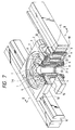
- an optical recording/reproducing apparatus is composed of a movable focus adjusting member (p), a carriage member (s) carrying the movable portion (p), a plate spring (t) coupling the carriage member (s) with the movable portion (p), and magnetic fluid (Lq) filling a gap between the carriage member (s) and the movable focus adjusting member (p).
- the movable focus adjusting member (p) is made up of an objective lens 1, a tubular lens holder 2 which is substantially rectangular in cross section and holds the objective lens 1, a pair of bobbins fit around the outer surface of the lens holder 2, a focus coil 4 wound around the lens holder 2, and a seek coil 5 wound around the bobbin 3. Those components are assembled into a unit.
- the lens holder 2 holds the objective lens 1 in the upper portion, and the central portion of the lens holder includes a tubular inner housing 21 whose inner diameter is smaller than that of the remaining portion, and a tubular outer housing 22 which is disposed around the inner housing by means of coupling plates 6 and 6'.
- a focus coil 4 is wound around the outer surface of the outer housing 22.
- a gap 8 is formed between the inner and outer housings 21 and 22.
- a rail 9 is disposed in the radial direction of an optical recording medium (not shown).
- a permanent magnet 10 is disposed along each rail 9, while the N pole of the permanent magnet is directed toward the bobbin 3.
- the permanent magnets 10 and 10' for seek adjust purposes are for forming magnetic forces directed toward the seek coils 5 and 5 wound around the bobbins 3.
- the carriage member (s) includes a carriage body 7 whose top and bottom faces are opened in the center portion, and a pair of focus adjust permanent magnets 30 mounted on the carriage body 7.
- a center portion of the carriage body 7 constitutes a tubular portion 31.
- This tubular portion 31 is inserted into the gap 8 between the inner and outer housings 21 and 22 of the lens holder 2.
- the inner wall of the tubular portion 31 slidably contacts the outer wall of the inner housing 21.
- each permanent magnet 30 is disposed such that its N pole faces the focus coil 4.
- the top and bottom ends of the permanent magnet 30 are mounted on the carriage body 7.
- Bearings 32 and 32' are mounted at the four corners of the carriage body 7. These bearings engage the rails 9 and 9' to allow the carriage member (s) to move in the radial direction of the optical recording medium.
- the plate spring (t) is constructed with a spiral metal member.
- the inner side of the plate spring (t) is mounted to the lens holder 2 in the movable focus adjusting member (p), while the outer sides of the plate springs are fastened to the top and bottom portions of the carriage body 7 in the carriage member (s).
- Use of the plate spring (t) allows the movable focus adjusting member (p) to vertically move.
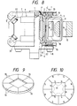
- a group of permanent magnets 70 which are arranged in a ring fashion as shown in Figs. 9 and 10, is fitted in each of the top and bottom opening portions of the carriage body 7.
- a magnetic liquid (Lq) is attracted and held by the permanent magnet group 70, which are disposed alternately in terms of polarity.
- the magnetic liquid (Lq) is held along the magnetic lines of force as formed among the permanent magnets 70 as shown in Fig. 10, while filling the gap between the lens holder 2 and the carriage body 7.
- "Marpomagna" may be used for the magnetic fluid (Lq).
- a convergent beam of light emitted from a light source (not shown) located outside a main body of the apparatus is incident on the objective 1 through a reflecting prism (not shown).
- the light beam converges on a focal plane of an optical recording medium (not shown) by the objective lens 1, thereby to effect the recording, reproducing and erasing of data in connection with the recording medium.
- a seek drive force (f s ) acts on the movable focus adjusting member (p), to effect the seek control and the tracking control.
- the magnetic lines of force emanating from the focus adjust permanent magnet 30 act on the focus coil 4.
- a focus drive force (f f ) acts on the movable focus adjusting member (p), to effect the focus control.
- the magnetic lines of force emanating from the focus adjust permanent magnet 30 act on the bobbin 3, namely on that part of seek coil 5 which is close to the lens holder 2. Further, the direction on the current flowing through the part of seek coil 5 close to the lens holder 2 is opposite to that of the current flowing through the seek coil 5 outside the bobbin.
- This seek coil 5 generates an action force (-f) that is opposite to the seek drive force (f s ).
- the force (-f) is an internal force, therefore a reaction force (f) responsive to the force (-f) is generated in the carriage member (s).
- the carriage (s) is driven by the force (-f) or the reaction force (f) directly acting on the carriage member (s) without the seek drive force acting on the seek coil. Therefore, a resonance phenomenon can be prevented that may occur in the seek control and the tracking control.
- the lens holder 2 and the carriage body 7 are coupled into a unit by filling the gap therebetween with the magnetic fluid (Lq) absorbing resonance of the lens holder 2 and the carriage body 7. Accordingly, the resonance phenomenon can reliable be absorbed.
- the movable focus adjusting member (p) and the carriage member (s) can be moved as a unit irrespective of a frequency of the current fed to the seek coil 5. Additionally, this ensures exact and reliable controls of seek and tracking operations.
- Fig. 12 is a graph showing the amplitude versus the frequency of a vibration of the movable focus adjusting member (p) in the seek direction when the movable focus adjusting member (p) and the carriage member (s) are vibrating.
- Fig. 13 is a graph showing the phase versus the frequency of a vibration of the movable focus adjusting member (p) when the movable focus adjusting member (p) and the carriage member (s) are vibrating. Those graphs show that no resonance phenomenon occurs.
- this first embodiment has the internal force generating means provided between the carriage member and the movable focus adjusting member.
- the carriage member is driven by utilizing an action force or a reaction force as an internal force, not the seek drive force acting on the movable focus adjusting member. Therefore, the resonance can be prevented irrespective of a frequency value of the current fed to the seek coil.
- the lens holder and the carriage body are coupled into a unit by filling the gap therebetween with the magnetic fluid absorbing resonance of the lens holder and the carriage body. Accordingly, the resonance phenomenon can reliably be absorbed.
- the movable focus adjusting member and the carriage member can be moved as a unit irrespective of the frequency of the current fed to the seek coil. Additionally, this ensures exact and reliable control of seek and tracking operations.
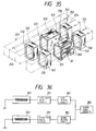
- first and second seek coils are assembled into the movable focus adjusting member (p) and the carriage member (s), respectively, as shown in Figs. 14 and 15.
- a first seek drive force (f s1 ) directly acts son the movable focus adjusting member (p), while a second seek drive force (f s2 ) directly acts on the carriage member (s). Therefore, there is no need for transferring the seek drive force to the carriage member (s) through the plate spring (t). Accordingly, the resonance phenomenon can be prevented irrespective of a frequency of the current fed to the first seek coil (s1) and the second seek coil (s2).
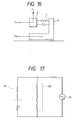
- the first and second seek coils (s1, s2) are connected in parallel, and the single drive circuit feeds current to those seek coils, as shown in Fig. 17, the phases Uc) of the currents flowing through the first and second seek coils (s1, s2) tend to shift one from other. This possibly cause the resonance phenomenon.
- first and second seek coils form a closed circuit
- the first and second seek coils form a closed circuit
- counter electromotive forces are generated in the seek coils due to self-induction. Since the resistance values of those coils are different, the counter electromotive forces are also different, to cause the phase shift of the currents of those coils.
- a third embodiment of the present invention provides certain advantages over the second embodiment.
- the first drive circuit for feeding current to the first seek coil and the second drive circuit for feeding current to the second seek coil are provided, to prohibit a closed circuit including those seek coils from being formed. Therefore, no phase shift will occur in the currents flowing through the seek coils, and the first and second seek coils are connected in series and to the single drive circuit. The currents flowing through those coils are equal, thus eliminating the phase shift.
- a ratio ((f s1 )/(f s2 )) of a first drive force (f s1 ), and a second drive force (f s2 ), which respectively act on the movable focus adjusting member and the carriage member when current is fed to the first and second seek coils, must be equal to a weight ratio (m/M) of the movable focus adjusting member (whose weight is "m”) and the carriage member (whose weight is "M”).
- m/M weight ratio
- a focus adjust magnet and a seek adjust magnet must be disposed for generating magnetic lines of force directed to those coils-. Those magnetic lines of force may be generated by a single magnet. This reduces the number of required parts, and hence reduces size reduction of the resultant apparatus, and magnetic fluid fills a gap between the movable focus adjusting member and the carriage member.
- This magnetic fluid may be composed of fluid, such as alkyl naphthalene, synthetic oil, and paraffin and magnetic particles, such as Fe3O4, ferromagnetic metal, and ferromagnetic alloy. "Marpomagna" may be used for the magnetic liquid.
- the permanent magnet mounted on the carriage member or the movable focus adjusting member is available for means for holding the magnet liquid.
- the magnetic fluid absorbs the resonance of the carriage member and the focus adjust portion to couple them into a unit and hence to reliable eliminate the resonance.
- an optical recording/reproducing apparatus is composed of a movable focus adjusting member (p), a carriage member (s) carrying the movable portion (p), a plate spring (t) coupling the carriage member (s) with the movable portion (p).
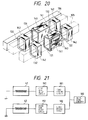
- the movable focus adjusting member (p) is made up of an objective lens 101, a tubular lens holder 102 holding the objective lens 101, a pair of bobbins fit around in the circumferential surface of the lens holder 102, a first seek coil 131 wound around the paired bobbins 131, and a focus coil 140 bonded on the first seek coil 141. These components are assembled into a unit. Within each bobbin 131, a center yoke 105 is disposed in the radial direction of an optical recording medium (not shown). The first seek coil 141 is wound around the outer surface of each bobbin 131. A permanent magnet 106, which generates magnetic lines of force directed toward the focus coils 140, is disposed along each center yoke 105.
- the carriage member (s) is composed of a carriage body 107 whose top and bottom faces are opened, bobbins 132 mounted to the front and rear end portions of the carriage 107, and second seek coils 142 around the bobbins 132.
- the center yoke 105 is inserted into the tubes of the bobbins 132.
- Bearings 171 are mounted to the four corners of the carriage body 107. The bearings engage rails 150 disposed in parallel to the center yokes 105, to allow the carriage member (s) to move in the radial direction of an optical recording medium.
- the plate spring (t) is constructed with a spiral metal member.
- the plate spring (t) is mounted at the inner side on the lens holder 2 in the movable focus adjusting member (p), while it is mounted at the outer side on the top and bottom opening portions of the carriage body 7 in the carriage member (s). With the aid of the plate spring (t), the movable focus adjusting member (p) is vertically movable.
- a first drive circuit 181 is coupled with the first seek coil 141 in the focus adjust portion (p).
- a second drive circuit 182 is coupled with the second seek coil 142 in the carriage member (s).
- the first and second drive circuits 181 and 182 are.connected together to a control signal generator 180, which is for generating a tracking error signal and a seek control signal.
- a first gain adjust circuit 191 is connected between the first drive circuit 181 and the first seek coil 141.
- a second gain adjust circuit 192 likewise is connected between the second drive circuit 182 and the second seek coil 142.
- the gain adjust circuits 191 and 192 are used for adjusting amplitude value of currents fed from the first and second drive circuits 181 and 182, respectively.
- a first drive force (f s1 ) and a second drive force (f s2 ), which act on the movable focus adjusting member (p) and the carriage member (s) respectively, are adjusted by the first and second gain adjust circuits 191 and 192 respectively.
- convergent bundle of light beams emitted from a light source (not shown) located outside the main body of the apparatus is incident on an objective lens 101 through a reflecting prism 172, and is focused on a focusing plane of an optical recording medium (not shown), thereby to effect the recording, reproducing and erasing of data in connection with the recording medium.
- a magnetic force generated by the permanent magnet 106 acts on the first and second seek coils 141 and 142, which are wound around the bobbins 131 and 132.
- a first drive force (f T1 ) acts on the movable focus adjusting portion (p)
- a second drive force (f T2 ) acts on the carriage member (s).
- the seek control and the tracking control are exercised.
- the magnetic force by the permanent magnet 106 acts on the focus coil 140.
- a focus driven force (f g ) acts on the movable focus adjusting member (p), as shown in Fig. 22.
- the focus control is exercised by the focus drive force.
- the apparatus In the seek control mode and in the tracking control mode, the first drive force (f T1 ) acts on the movable focus adjusting member (p), while the second drive force (f T2 ) acts on the carriage member (s).
- the resonance phenomenon can be prevented without transferring a seek drive force through the plate spring (t) to the carriage member, because the movable focus adjusting member (p) and the carriage member (s) are moved in a unit fashion.
- first drive circuit 181 for feeding current to the first seek coil 141 and the second drive circuit 182 for feeding current to the second seek coil 142 are provided. No closed circuit is formed between the first and second seek coils 141 and 142. No phase shift occurs in the current fed to each of the seek coils 141 and 142. This feature additionally contributes to prevent the resonance phenomenon of the movable focus adjusting member (p) and the carriage member (s).
- the movable focus adjusting member (p) and the carriage member (s) can be simultaneously moved irrespective of a frequency of the current fed to each of the seek coils 141 and 142. Reliable seek and tracking controls are ensured.
- Fig. 23 is a graph showing a relationship between an amplitude and frequency of an vibration of the movable focus adjusting member (p) when the movable focus adjusting member (p) and the carriage member (s) are vibrating.
- Fig. 24 is a graph showing a relationship between phase and frequency of an vibration of the movable focus adjusting member (p) when the movable focus adjusting member (p) and the carriage member (s) are vibrating. As seen from those graphs, no resonance phenomenon occurs.
- the magnetic lines of force directed toward the focus coils 140 and the first seek coils 141 in the movable focus adjusting member (p), and the magnetic lines of force toward the second seek coils 142 in the carriage member (s) are generated by a pair of permanent magnets 106. This leads to reduction of the number of required parts, and hence reduction of the apparatus size.
- a fourth embodiment according to the present invention is different from the third embodiment in that magnetic fluid is used to fill a gap between the movable focus adjusting member (p) and carriage member (s), and in a current feed system for feeding current to the first and second seek coils mounted on the movable focus adjusting member (p) and the carriage member (s).
- an optical recording/reproducing apparatus is composed of a movable focus adjusting member (p), a carriage member (s) carrying the movable member (p), a plate spring (t) coupling the carriage member (s) with the movable member (p), and magnetic liquid (Lq) filling a gap between the carriage member (s) and the movable focus adjusting member (p).
- the magnetic liquid (Lq) is attracted and held by the permanent magnet groups 175 to 175. As shown, those permanent magnets are disposed alternately in terms of polarity.
- the magnetic liquid (Lq) is held along the magnetic lines of force as formed among the permanent magnets 175, while filling the gap between the lens holder 102 in the movable focus adjusting member (p) and the carriage body 107.
- "Marpomagna" may be used for the magnetic liquid (Lq).
- the first and second seek coils 141 and 142 mounted on the movable focus adjusting member (p) and the carriage member (s), as shown in Fig. 28, are connected to a single drive circuit 185 in series, which is for feeding current to those seek coils 141 and 142.
- reference numeral 180 designates a control circuit for producing a tacking error signal and a seek control signal.
- the first drive force (f T1 ) acts on the movable focus adjusting member (p), while the second drive force (f T2 ) directly acts on the carriage member (s).
- the resonance phenomenon can be prevented without transferring a seek drive force through the plate spring (t) to the carriage member, because the movable focus adjusting member (p) and the carriage member (s) are moved in a unit fashion.
- the first and second seek coils 141 and 142 are connected in series to the single drive circuit 85. Accordingly, the same current flow through those seek coils, with no shift of phase. Therefore, the fourth embodiment can reliably prevent the resonance of the movable focus adjusting member (p) and the carriage member (s).
- the magnetic liquid (Lq) which fills the gap between the lens holder 102 and the carriage body 107, absorbs resonance in those components, and unify them. This feature also contributes to prevent the resonance.
- the movable focus adjusting member (p) and the carriage member (s) can be moved in a unit fashion irrespective of a frequency value of the current fed to the first and second seek coils 141 and 142. Consequently, an exact tracking control is ensured.
- the first drive circuit for feeding current to the first seek coil and the second drive circuit for feeding current to the second seek coil are provided, to prohibit a closed circuit including those seek coils from being formed. Therefore, no phase shift will occur in the currents flowing through the seek coils.
- first and second seek coils are connected in series and to the single drive circuit. The currents flowing through those coils are equal, eliminating the phase shift.
- a ratio of a first drive force and a second drive force, which respectively act on the movable focus adjusting member and the carriage member when current is fed to the first and second seek coils, is equal to a weight ratio of the movable focus adjusting member and the carriage member. This feature prevents a resonance of the movable focus adjusting member and the carriage member.
- magnetic liquid fills a gap between the movable focus adjusting member and the carriage member.
- the magnetic fluid absorbs the resonance of the carriage member and the focus adjust portion to couple them into a unit and hence to reliable eliminate the resonance.
- a first seek drive force (f s1 ) directly acts on the movable focus adjusting member (p), while a second seek drive force (f s2 ) directly acts on the carriage member (s). Therefore, there is no need for transferring the seek drive force to the carriage member (s) through the plate spring (t). Accordingly, the resonance phenomenon can be prevented irrespective of a frequency of the current fed to the first seek coil (s1) and the second seek coil (s2).
- a permanent magnets (u) are disposed along a center magnetic yokes (kc) as respectively inserted into a hollows (m3, m4) of first coil support (m1) and second coil support (m2) of the first seek coil (s1) and second seek coil (s2). In this way, a uniform magnetic filed is developed toward each of the first seek coil (s1) and the second seek coil (s2).
- An endless magnetic yoke is formed by the center magnetic yoke (kc), a back magnetic yoke (kb) disposed along the center magnetic yoke (kc), and a pair of side magnetic yokes (ks, ks) which connect the center magnetic yoke (kc) and the back magnetic yoke (kb) at both ends of the center magnetic yoke (kc) the back magnetic yoke (kb).
- the endless magnetic yoke (k) prevents a magnetic filed from being dispersed, thereby to improve the efficiency of shaping a magnetic field developed from the permanent magnet (u).
- each center magnetic yoke (kc) forms a magnetic circuit ( ⁇ ) as shown in Fig. 32.
- a region where each magnetic circuit ( ⁇ ) is closer to the side magnetic yoke (ks) magnetic lines of force pass through the side magnetic yoke (ks), and therefore little influence the uniform magnetic field of the permanent magnet.
- the magnetic lines of force pass through a gap between the center magnetic yoke (kc) and the back magnetic yoke (kb), so as to greatly influence the magnetic filed from the permanent magnet.
- a sixth embodiment of the present invention provides certain advantages over the second embodiment.
- a phase of the current flowing through each seek coil is shift, motion timings of the movable focus adjusting member and the carriage member tend to stagger. In an extreme case, a resonance occurs between the movable focus adjusting member and the carriage member.
- a first drive circuit for feeding current to the first seek coil and a second drive circuit for feeding current to the second seek coil are provided, so as not form a closed circuit between the first and second seek coils.
- a single drive circuit for feeding current to the first and second seek coils is provided. Those seek coils are connected in series, thereby to prevent a phase shift of the current.
- the above relation can be satisfied by adjusting the number of turns of each seek coil, amplitude of the current fed to each seek coil, a magnetic force of each seek adjust magnet, and the like.
- the apparatus using a single drive circuit it is impossible to individually adjust the amplitudes of the currents fed to the coils and the like. Accordingly, in this type of the apparatus, the number of turns of each seek coil, and the magnetic force of the seek adjust magnet are adjusted for satisfying the relation.
- the focus adjust magnet and the seek adjust magnet must be provided for generating magnetic lines of force toward the focus coil and the first seek coil, which are provided in movable focus adjusting member, and the second seek coil provided in the carriage member.
- the magnet may be replaced by a single magnet. Use of the single magnet reduces the number of necessary parts, and consequently the size of the resultant apparatus.
- limits of configuring the movable focus adjusting member and the carriage member, and limit of working accuracy sometimes cause a non-uniform gap between the movable focus adjusting member and the carriage member. Even if the first and second seek coils are respectively installed in the movable focus adjusting member and the carriage member, a resonance sometimes occur due to the non-uniform gap.
- This magnetic fluid may be composed of fluid, such as alkyl naphthalene, synthetic oil, and paraffin, and magnetic particles, such as Fe3O4, ferromagnetic metal, and ferromagnetic alloy. "Marpomagna" may be used for the magnetic liquid.
- the permanent magnet mounted on the carriage member or the movable focus adjusting member is available for means for holding the magnetic liquid.
- an optical recording/reproducing apparatus is composed of a movable focus adjusting member (p), a carriage member (s) carrying the movable focus adjusting member (p), a plate spring (t) coupling the carriage member (s) with the movable focus adjusting member (p), a pair of endless magnetic yokes 205, and a permanent magnet 206.
- the movable focus adjusting member (p) is made up of an objective lens 201, a tubular lens holder 202 holding the objective lens 201, a pair of bobbins fit around in the circumferential surface of the lens holder 202, a first seek coil 231 wound around the paired bobbing 231, and a focus coil 240 bonded on the first seek coil 241. Those components are assembled into a unit.
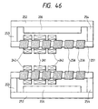
- Each endless magnetic yoke 205 is made up of a center magnetic yoke 251 inserted in the tube of the bobbin 231 with a gap therebetween to allow a focus movement, a back magnetic yoke 252 disposed along the center magnetic yoke 251, and a pair of side magnetic yokes 253 and 254 respectively bridging both ends of the center magnetic yokes 251 and the back magnetic yokes 252.
- a permanent magnet 206 is disposed on the side of the back magnetic yoke 252, which faces the center magnetic yoke 251, and develops a uniform magnetic filed toward the first and second seek coils 241 and 242.
- a tubular short ring 266 is fit around the center magnetic yoke 251.
- the short ring 266 is made of metal, such as copper, and serves as a means for reducing the magnetic field developed when the current is fed.
- the carriage member (s) is composed of a carriage body 207 whose top and bottom faces are opened, bobbins 232 mounted to the front and rear end portions of the carriage body 207, and second seek coils 242 around the bobbins 232.
- the center magnetic yoke 251 is inserted into the tubes of the bobbins 232.
- Bearings 271 are mounted to the four corners of the carriage body 207. The bearings engage rails 250 disposed in parallel to the center yokes 251, to allow the carriage member (s) to move in the radial direction of an optical recording medium.
- the plate spring (t) is constructed with a spiral metal member.
- the plate spring (t) is mounted at the inner side on the lens holder 202 in the movable focus adjusting member (p), while it is mounted at the outer side on the top and bottom opening portions of the carriage body 207 in the carriage member (s). With the aid of the plate spring (t), the movable focus adjusting member (p) is vertically movable.
- a first drive circuit 281 is coupled with the first seek coil 241 in the focus adjust portion (p).
- a second drive circuit 282 is coupled with the second seek coil 242 in the carriage member (s).
- the first and second drive circuits 281 and 282 are connected to a control signal generator 280 in parallel, which is for generating a tracking error signal and a seek control signal.
- a first gain adjust circuit 291 is connected between the first drive circuit 281 and the first seek coil 241.
- a second gain adjust circuit 292 likewise is connected between the second drive circuit 282 and the second seek coil 242.
- the gain adjust circuits 291 and 292 are used for adjusting amplitude value of currents fed from the first and second drive circuits 281 and 282, respectively.
- a first drive force (f R1 ) and a second drive force (f R2 ), which act on the movable focus adjusting member (p) and the carriage member (s), are respectively adjusted by the first and second gain adjust circuits 291 and 292.
- convergent beam of light emitted from a light source (not shown) located outside the main body of the apparatus is incident on art objective lens 201 through a reflecting prism 272, and is focused on a focusing lend plane of an optical recording medium (not shown), thereby to effect the recording, reproducing and erasing of data in connection with the recording medium.
- a magnetic force generated by the permanent magnet 6 acts on the first and second seek coils 241 and 242, which are wound around the bobbins 231 and 232.
- a first drive force (f R1 ) acts on the movable focus adjusting portion (p)
- a second drive force (f R 1) acts on the carriage member (s).
- the seek control and the tracking control are exercised.
- the magnetic force by the permanent magnet 6 acts on the focus coil 240.
- a focus drive force (f n ) acts on the movable focus adjusting member (p), as shown in Fig. 39.
- the focus control is exercised by the focus drive force.
- the short ring 255 as the means for reducing the magnetic fields developed by the current feeding is mounted on the circumference surface of each center magnetic yoke 251. Therefore, it is possible to prevent the uniform magnetic field by the permanent magnet 206 being deformed when the apparatus is in a seek control mode or in a tracking control mode.
- the seek control mode or the tracking control mode when current is fed to the first and second seek coils 242 from the first and second drive circuits 281 and 282, magnetic fields are developed from these seek coils 241 and 242. Then, the magnetic fields magnetize the center magnetic yokes 251, which develop additional magnetic fields. Those magnetic fields developed from the center magnetic yokes tend to disturb the uniform magnetic field by the permanent magnet 206.
- the short rings 255 are mounted on the center magnetic yokes 251. Accordingly, when the carriage member (s) carrying the first and second seek coils 241 and 242 are moved when the magnetic fields by the seek coils exist, currents whose direction is opposite to that of the current fed to the coils are caused in the surfaces of the short rings 255 by the electromagnetic induction caused by the movement of the carriage member (s). As shown in Fig. 37, the currents caused by the electromagnetic induction cause the short rings 255 to develop magnetic fields whose direction is opposite to that of the magnetic fields as developed by the current as fed. The magnetic fields by the short rings 255 cancel the magnetic fields by the center magnetic yokes 251 yokes. For this reason, as shown in Fig. 38, a magnetic field developed by the permanent magnet 206, which act on the first and second seek coils 241 and 242, can be maintained constantly regardless the fact that wherether feeding current in applied to the seek coils 241 and 242.
- first drive circuit 281 for feeding current to the first seek coil 241 and second drive circuit 282 for feeding current to the second seek coil 242 are provided. No closed circuit is formed between the first and second seek coils 241 and 242. No phase shift occurs in the current fed to each of the seek coils 241 and 242. This feature additionally contributes to prevent the resonance phenomenon of the movable focus adjusting member (p) and the carriage member (s).
- the movable focus adjusting member (p) and the carriage member (s) can be simultaneously moved irrespective of a frequency of the current fed to each of the seek coils 241 and 242. Reliable seek and tracking controls are ensured.
- Fig. 40 is a graph showing a relationship between amplitude and frequency of an vibration of the movable focus adjusting member (p) when the movable focus adjusting member (p) and the carriage member (s) are vibrating.
- Fig. 41 is a graph showing a relationship between phase and frequency of an vibration of the movable focus adjusting member (p) when the movable focus adjusting member (p) and the carriage member (s) are vibrating. As seen from those graphs, no resonance phenomenon occurs.
- An optical recording/reproducing apparatus is different from the apparatus according to the fifth embodiment in the following points.
- a wire conductor in place of the short ring 255 as the magnetic field reducing means, is wound around each center magnetic yoke 251.
- a magnetic field adjust drive circuit 285 for feeding current to the wire conductor 256 is provided.
- the remaining arrangement of the instant embodiment is substantially the same as that of the fifth embodiment.
- the wire conductor 256 is made of a wire metal, such as copper.
- the center magnetic yoke 251 is covered with an insulating layer (not shown).
- the conductor 256 is uniformly wound on the insulating layer.
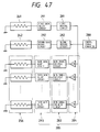
- the magnetic filed adjust drive circuit 285 is connected in parallel with the control signal generator 280, and the first and second drive circuits 281 and 282 are connected to the control signal generator 280 in parallel.
- the circuit 285 consists of a signal inverting circuit 284 for inverting an output signal of the control signal generator 280, a wire conductor drive circuit 283 for feeding the wire conductor 256 on a current whose direction is opposite to that of the currents fed to the first and second seek coils 241 and 242, and a third gain adjust circuit 293 for adjusting an amplitude of the current fed from the wire conductor drive circuit 283.
- the optical recording/reproducing apparatus is uniquely provided with the wire conductor 256 wound around each center magnetic yoke 251, and the conductor drive circuit 283 for feeding the wire conductor 256 on a current whose direction is opposite to that of the currents fed to the first and second seek coils 241 and 242.
- the seventh embodiment like the fifth embodiment, can effectively prevent the uniform magnetic field by the permanent magnet 206 from being disturbed or deformed when the apparatus is in the seek control mode or the tracking mode.
- the current is fed to the first and second seek coils 241 and 241 with the center magnetic yoke 251 being magnetized. Therefore, the magnetic field is developed from the center magnetic yoke 251.
- current whose direction is opposite to that of the current to the seek coils is fed to the wire conductor 256, from the magnetic field adjust drive circuit 285. Accordingly, the wire conductor 256 develops a magnetic field in which a direction of the magnetic field is opposite to the direction of the magnetic field developed by the center magnetic yoke 251.
- each seek coil is canceled by the magnetic field of the wire conductor 256 so that, a distribution of the magnetic field developed by the permanent magnet 206 is reduced, and the magnetic field developed by the permanent magnet 206 to the first and second seek coils is constantly maintained regardless the fact that the whether the current flows to the first and second seek coils or not.
- the magnetic fields applied by the yokes by could be minimized by adjusting the current applied to the wire conductor 256.
- the magnetic field which is developed by the permanent magnet 206 and acts on both the first and second seek coils 241 and 242, can be applied more uniform in distribution.
- the optical recording/reproducing apparatus is different from the apparatus according to the fifth embodiment in the following points.
- a plurality of wire conductors 256 in place of the short ring 255 as the magnetic field reducing means, are wound around each center magnetic yoke 251.
- a plurality of magnetic field adjust drive circuits 285 for feeding current to the wire conductors 256 are provided.
- the remaining arrangement of the seventh embodiment is substantially the same as that of the fifth embodiment.
- Each wire conductor 256 is of a wire metal, such as copper.
- the center magnetic yoke 251 is covered with an insulating layer (not shown)
- the conductors 256 are disposed along the wire conductor and separately at predetermined intervals, and uniformly wound around the insulating layer at the predetermined locations.
- the magnetic field adjust drive circuits 285 are connected in parallel to each other, and for reception with the control signal generator 280, and are connected also in parallel with the first and second drive circuits 281 and 282.
- Each circuit 285 consists of signal inverting circuit 284 for inverting an output signal of the control signal generator 280, a wire conductor drive circuit 283 for feeding to the wire conductor 256 a current whose direction is opposite to that of the currents fed to the first and second seek coils 241 and 242, and a third gain adjust circuit 293 for adjusting an amplitude of the current fed from the wire conductor drive circuit 283.
- the optical recording/reproducing apparatus is uniquely provided with the wire conductors 256 which are disposed along the wire conductor and separately at predetermined intervals and wound around each center magnetic yoke 251, and the conductor drive circuit 283 for feeding the wire conductor 256 to a current whose direction is opposite to that of the current fed to the first and second seek coils 241 and 242.
- the seventh embodiment like the fifth and sixth embodiments, can effectively prevent the uniform magnetic field by the permanent magnet 206 from being disturbed or deformed when the apparatus is in the seek control mode or the tracking mode. Accordingly, the mechanical vibration characteristics required for tracking and seek controls can readily be obtained.
- a plurality of wire conductors 256 are provided.
- a plurality of magnetic field drive circuits 285 for feeding current to the wire conductors are provided in association with the wire conductors. Current may be selectively fed to only the wire conductors as required. In this respect, electric power is saved.
- the electromagnetic forces acting on the first and second seek coils can be controlled to be desired values. This ensures exact controls of seek and tracking operations.
- each of the magnetic field reducing means is conductive means, the conductive means being disposed extending in the longitudinal direction of each center magnetic yoke and covering the center magnetic yoke.
- each of the magnetic field reducing means includes:
- the above arrangement further reduces the influence by the yoke developed magnetic field, and contributes to making the seek and tracking controls more exact.
- each of the magnetic field reducing means includes:
- an intensity of the magnetic field whose direction is opposite to that of the current fed to each yoke can be controlled to be a desired value by adjusting the current fed to each wire conductor. Therefore, the arrangement according to those fifth to seventh embodiment further reduces the influence by the yoke developed magnetic field, and contributes to making the seek and tracking controls more exact.
- only desired drive circuits may be selectively driven. This feature saves the electric power consumed by the apparatus.
- the conductive covering means and the wire conductor provided on the outer surface of each center magnetic yoke may be any of copper, silver platinum, copper alloy, iron alloy, aluminum alloy, and the like.
- the covering means may directly be formed on the outer surface of each center yoke by a film forming method, such as a vapor depositing method. Any of the metals as mentioned above is formed to be tubular. The center magnetic yoke is inserted into the tubular metal member. Any suitable method may be used for forming the converging means.
Landscapes
- Optical Recording Or Reproduction (AREA)
Claims (15)
- Appareil d'enregistrement/reproduction optique qui comprend :- un élément (p) de réglage de la focalisation incluant :- un moyen (1) pour faire converger la lumière sur le plan focal d'un support d'enregistrement optique,- un moyen (4) formant bobine de concentration qui réagit à un premier courant pour entraîner, par une force électromagnétique, le moyen de convergence (1) dans une direction sensiblement verticale par rapport au plan focal,- un moyen (5) formant bobine de recherche, activé par un second courant pour entraîner, par une force électromagnétique, le moyen de convergence (1) dans une direction radiale du support d'enregistrement optique,- un moyen formant chariot (s) comprenant un dispositif d'entraînement dans la direction radiale,- un moyen formant ressort (t), dont une première partie est couplée à l'élément (p) de réglage de la focalisation et dont une seconde partie est couplée au moyen formant chariot (s), qui sert à soutenir l'élément (p) de réglage de la focalisation,caractérisé en ce que l'appareil comprend en outre :- un moyen (30) de production d'une force magnétique entre l'élément (p) de réglage de la focalisation et le moyen formant chariot (s), servant à produire une force magnétique qui maintient l'élément (p) de réglage de la focalisation sensiblement immobile dans la direction radiale par rapport au moyen formant chariot (s), et- un moyen pour fournir le second courant de telle sorte que :

- Appareil d'enregistrement/reproduction optique selon la revendication 1, dans lequel ledit moyen (30) de production d'une force magnétique comprend un aimant (30) de réglage de la focalisation placé dans la partie tubulaire d'un corps de bobine (3) sur lequel est enroulé ledit moyen (5) formant bobine de recherche, les parties d'extrémité dudit aimant de réglage (30) étant fixées audit moyen formant chariot (s).
- Appareil d'enregistrement/reproduction optique selon la revendication 1 ou 2, comprenant en outre :- un moyen (Lq) d'absorption de la résonance, placé dans un interstice entre ledit élément (p) de réglage de la focalisation et ledit moyen formant chariot (s) pour absorber une résonance dudit élément (p) de réglage de la focalisation et dudit moyen formant chariot (s), et- un moyen de maintien (70) placé sur l'un au moins dudit élément mobile (p) de réglage de la focalisation et dudit moyen formant chariot (s) pour retenir ledit moyen (Lq) d'absorption de la résonance.
- Appareil d'enregistrement/reproduction optique qui comprend :- un élément (p) de réglage de la focalisation incluant :- un moyen (1, 101, 201) pour faire converger la lumière sur le plan focal d'un support d'enregistrement optique,- un moyen (140, 240) formant bobine de concentration qui réagit à un courant de bobine de concentration pour entraîner, par une force électromagnétique, le moyen de convergence (1, 101, 201) dans une direction sensiblement verticale par rapport au plan focal,- un premier moyen (s₁) formant bobine de recherche, réagissant à un courant pour entraîner, par une force électromagnétique, le moyen de convergence (1, 101, 201) dans une direction radiale du support d'enregistrement optique,- un moyen (s) formant chariot pour procéder à un entraînement dans la direction radiale par une force électromagnétique,- un moyen formant ressort (t), dont une première partie est couplée à l'élément (p) de réglage de la focalisation et dont une seconde partie est couplée au moyen formant chariot (s), qui sert à soutenir l'élément (p) de réglage de la focalisation,caractérisé en ce que l'appareil comprend en outre un second moyen (s₂) formant bobine de recherche, de sorte que les premier et second moyens (s₁, s₂) formant bobines de recherche réagissent à au moins un courant pour entraîner le moyen de convergence (1, 101, 201) dans la direction radiale du support d'enregistrement optique grâce à une force électromagnétique,
sachant que le rapport entre la première force d'entraînement f₁ et la seconde force d'entraînement f₂, quand un courant est envoyé auxdits premier et second moyens (s₁, s₂) formant bobines de recherche, satisfait à la condition :
- Appareil d'enregistrement/reproduction optique selon la revendication 4, comprenant en outre :- un moyen (Lq) d'absorption de la résonance, placé dans un interstice entre ledit élément (p) de réglage de la focalisation et ledit moyen formant chariot (s) pour absorber une résonance dudit élément (p) de réglage de la focalisation et dudit moyen formant chariot (s), et- un moyen de maintien (175) placé sur l'un au moins dudit élément de réglage de la focalisation et dudit moyen formant chariot pour retenir ledit moyen d'absorption de la résonance.
- Appareil d'enregistrement/reproduction optique selon la revendication 5, comprenant en outre des éléments magnétiques (106, 206) pour créer une ligne de force magnétique.
- Appareil d'enregistrement/reproduction optique selon la revendication 6, comprenant en outre un moyen de réduction de la distribution pour réduire la distribution du champ magnétique produit par lesdits éléments magnétiques (106, 206).
- Appareil d'enregistrement/reproduction optique selon la revendication 7, dans lequel le moyen de réduction de la distribution est formé par un moyen (kc, kb, ks, ks, 251, 252, 253, 254) de production magnétique sans fin qui forme une culasse magnétique sans fin (205).
- Appareil d'enregistrement/reproduction optique selon l'une quelconque des revendications 4 à 8, comprenant en outre un moyen électrique (255, 266) de réduction du champ magnétique pour réduire le champ magnétique quand un courant est appliqué auxdits premier et second moyens formant bobines de recherche (s₁, s₂, 241, 242).
- Appareil d'enregistrement/reproduction optique selon la revendication 9, dans lequel ledit moyen (k) de production
magnétique sans fin comprend une culasse magnétique centrale (kc, 251) disposée dans lesdits premier et second moyens de support (m1, m2), suivant ladite direction radiale dudit support d'enregistrement optique, une culasse magnétique arrière (kb, 252) placée le long de ladite culasse magnétique centrale (kc), une première culasse magnétique latérale (ks, 253) couplant une extrémité de la culasse magnétique centrale (kc) à une extrémité de la culasse magnétique arrière (kb, 252) et une seconde culasse magnétique latérale (ks, 254) couplant l'extrémité de la culasse magnétique centrale (kc, 251) à une autre extrémité de la culasse magnétique arrière (kb, 252). - Appareil d'enregistrement/reproduction optique selon la revendication 10, dans lequel ledit moyen électrique (255, 266) de réduction du champ magnétique comprend un matériau électroconducteur qui recouvre une partie extérieure de ladite culasse magnétique centrale (kc, 251) dans la direction longitudinale de ladite culasse magnétique centrale (kc, 251).
- Appareil d'enregistrement/reproduction optique selon la revendication 10, dans lequel ledit moyen électrique (255, 266) de réduction du champ magnétique comprend un élément isolant électrique qui recouvre une surface extérieure de ladite culasse magnétique centrale (kc, 251) et un élément électroconducteur (256) uniformément enroulé sur ledit élément isolant électrique.
- Appareil d'enregistrement/reproduction optique selon la revendication 12, comprenant en outre un moyen (285) formant circuit d'excitation réglable du champ magnétique, servant à appliquer audit moyen électrique (255, 266) de réduction du champ magnétique un courant dont la direction est opposée à la direction desdits premier et second moyens formant bobines de recherche (s₁, s₂, 241, 242).
- Appareil d'enregistrement/reproduction optique selon la revendication 10, dans lequel ledit moyen électrique (255, 266) de réduction du champ magnétique comprend un élément isolant électrique qui recouvre une surface extérieure de ladite culasse magnétique centrale (kc, 251) et une pluralité de fils conducteurs (256) enroulés indépendamment et à intervalles prédéterminés autour dudit élément isolant dans ladite direction longitudinale de ladite culasse magnétique centrale (kc, 251).
- Appareil d'enregistrement/reproduction optique selon la revendication 14, comprenant en outre des circuits (285) d'excitation réglable de champs magnétiques servant à appliquer auxdits fils conducteurs (256) un courant dont la direction est opposée à la direction desdits premier et second moyens formant bobines de recherche (s₁, s₂, 241, 242).
Applications Claiming Priority (6)
| Application Number | Priority Date | Filing Date | Title |
|---|---|---|---|
| JP166800/89 | 1989-06-30 | ||
| JP16680089A JPH0648539B2 (ja) | 1989-06-30 | 1989-06-30 | 光学的記録再生装置 |
| JP19057689A JPH0358328A (ja) | 1989-07-25 | 1989-07-25 | 光学的記録再生装置 |
| JP190576/89 | 1989-07-25 | ||
| JP4463490A JPH0622059B2 (ja) | 1990-02-27 | 1990-02-27 | 光学的記録再生装置 |
| JP44634/90 | 1990-02-27 |
Publications (3)
| Publication Number | Publication Date |
|---|---|
| EP0405604A2 EP0405604A2 (fr) | 1991-01-02 |
| EP0405604A3 EP0405604A3 (en) | 1992-05-20 |
| EP0405604B1 true EP0405604B1 (fr) | 1996-04-10 |
Family
ID=27291970
Family Applications (1)
| Application Number | Title | Priority Date | Filing Date |
|---|---|---|---|
| EP90112502A Expired - Lifetime EP0405604B1 (fr) | 1989-06-30 | 1990-06-29 | Appareil d'enregistrement/reproduction magnéto-optique |
Country Status (3)
| Country | Link |
|---|---|
| US (1) | US5218587A (fr) |
| EP (1) | EP0405604B1 (fr) |
| DE (1) | DE69026429T2 (fr) |
Families Citing this family (19)
| Publication number | Priority date | Publication date | Assignee | Title |
|---|---|---|---|---|
| US5265079A (en) * | 1991-02-15 | 1993-11-23 | Applied Magnetics Corporation | Seek actuator for optical recording |
| JPH0460929A (ja) * | 1990-06-25 | 1992-02-26 | Canon Inc | 光学ヘッド及び該光学ヘッドを備えた光学的情報記録再生装置 |
| DE69126688T2 (de) * | 1990-08-29 | 1997-12-18 | Toshiba Kawasaki Kk | Abspielgerät für optische Platten zur optischen Verarbeitung von Information |
| JPH0752511B2 (ja) * | 1991-01-22 | 1995-06-05 | 富士ゼロックス株式会社 | 光学的情報記録再生装置 |
| US5677899A (en) | 1991-02-15 | 1997-10-14 | Discovision Associates | Method for moving carriage assembly from initial position to target position relative to storage medium |
| DE69232757T2 (de) * | 1992-01-21 | 2003-02-06 | Fujitsu Ltd., Kawasaki | Optisches Plattengerät mit reduzierten Abmessungen |
| US5289442A (en) * | 1992-06-19 | 1994-02-22 | U.S. Philips Corporation | Optical scanner with a long fast access stroke |
| EP0574996B1 (fr) * | 1992-06-19 | 1997-09-03 | Koninklijke Philips Electronics N.V. | Dispositif destiné à l'exploration optique d'une surface |
| EP0574995B1 (fr) * | 1992-06-19 | 1998-01-21 | Koninklijke Philips Electronics N.V. | Dispositif destiné à l'exploration optique d'une surface |
| KR100200808B1 (ko) * | 1992-11-30 | 1999-06-15 | 윤종용 | 광픽업 구동장치 |
| US5598386A (en) * | 1995-01-23 | 1997-01-28 | Eastman Kodak Company | Optimized linear motors for focus/tracking actuators in optical disk drives |
| JPH10308083A (ja) * | 1997-05-01 | 1998-11-17 | Fujitsu Ltd | ヘッド駆動装置及び光ディスク装置 |
| JP3895471B2 (ja) * | 1998-07-17 | 2007-03-22 | 富士通株式会社 | レンズアクチュエータ |
| JP2000048374A (ja) * | 1998-07-30 | 2000-02-18 | Matsushita Electric Ind Co Ltd | ディスク記録再生装置 |
| US6865743B2 (en) * | 1999-02-24 | 2005-03-08 | Matsushita Electric Industrial Co., Ltd. | Optical head and method of manufacturing the same |
| US6097552A (en) * | 1999-05-27 | 2000-08-01 | Polaroid Corporation | Autofocus actuator device |
| JP2001273647A (ja) * | 2000-03-29 | 2001-10-05 | Sanyo Electric Co Ltd | 光ディスク装置 |
| US6721260B2 (en) * | 2001-09-04 | 2004-04-13 | Hewlett-Packard Development Company L.P. | Electromagnetically controlled drive system and method |
| US20040223423A1 (en) * | 2002-04-11 | 2004-11-11 | Shiro Tsuda | Optical pick-up actuator and method for assembling an optical pick-up actuator |
Family Cites Families (16)
| Publication number | Priority date | Publication date | Assignee | Title |
|---|---|---|---|---|
| GB2052829B (en) * | 1979-04-27 | 1983-01-12 | Olympus Optical Co | Apparatus for driving objective lens in tracking direction |
| JPS576444A (en) * | 1980-06-16 | 1982-01-13 | Olympus Optical Co Ltd | Objective lens driving device |
| JPS5720927A (en) * | 1980-07-09 | 1982-02-03 | Olympus Optical Co Ltd | Objective lens driver |
| US4482986A (en) * | 1981-01-30 | 1984-11-13 | Sony Corporation | Objective lens mount for optical disc player |
| JPS57147143A (en) * | 1981-03-07 | 1982-09-10 | Olympus Optical Co Ltd | Objective lens driving device |
| US4507764A (en) * | 1981-08-25 | 1985-03-26 | Olympus Optical Co., Ltd. | Objective lens drive device with tracking error correction with flux of opposite direction |
| FR2522860B1 (fr) * | 1982-03-02 | 1989-07-13 | Thomson Csf | Tete optique d'ecriture-lecture d'un disque optique et dispositif optique associe a une telle tete |
| US4583212A (en) * | 1982-08-13 | 1986-04-15 | Ricoh Company, Ltd. | Record/playback head positioning device for optical disc apparatus |
| US4660190A (en) * | 1983-01-25 | 1987-04-21 | Sharp Kabushiki Kaisha | Optical focus position control in optical disc apparatus |
| US4504935A (en) * | 1983-02-14 | 1985-03-12 | U.S. Philips Corporation | Electrodynamic focus and radial slide drive for an optical disc system |
| US4641296A (en) * | 1983-04-28 | 1987-02-03 | Nippon Kogaku K.K. | Optical head for information recording apparatus |
| JPS60239943A (ja) * | 1984-05-15 | 1985-11-28 | Matsushita Electric Ind Co Ltd | 光学ヘツド |
| US4782476A (en) * | 1986-06-24 | 1988-11-01 | Sharp Kabushiki Kaisha | Objective lens-driving unit |
| JPS6350927A (ja) * | 1986-08-20 | 1988-03-03 | Matsushita Electric Ind Co Ltd | 対物レンズ駆動装置 |
| JPS6490838A (en) * | 1987-09-30 | 1989-04-07 | Tokyo Keiki Kk | Obstacle detector for working vehicle |
| JP2595712B2 (ja) * | 1989-04-12 | 1997-04-02 | 富士ゼロックス株式会社 | 光学的記録再生装置 |
-
1990
- 1990-06-29 DE DE69026429T patent/DE69026429T2/de not_active Expired - Lifetime
- 1990-06-29 US US07/545,521 patent/US5218587A/en not_active Expired - Lifetime
- 1990-06-29 EP EP90112502A patent/EP0405604B1/fr not_active Expired - Lifetime
Also Published As
| Publication number | Publication date |
|---|---|
| EP0405604A2 (fr) | 1991-01-02 |
| US5218587A (en) | 1993-06-08 |
| DE69026429T2 (de) | 1996-11-14 |
| EP0405604A3 (en) | 1992-05-20 |
| DE69026429D1 (de) | 1996-05-15 |
Similar Documents
| Publication | Publication Date | Title |
|---|---|---|
| US5218587A (en) | Magnetic optical recording/reproducing apparatus | |
| US4321701A (en) | Device for displacing the reading head of a video disc in radial and vertical directions | |
| US4568142A (en) | Objective lens drive apparatus | |
| EP0371799B1 (fr) | Appareil entraînant une lentille d'objectif utilisant une substance viscoélastique | |
| US4479051A (en) | Apparatus for driving objective lens in tracking direction | |
| EP0287285B1 (fr) | Dispositif d'entraînement de parties optiques d'une tête d'enregistrement optique | |
| EP0251561B1 (fr) | Générateur de champ magnétique | |
| US4750164A (en) | Optical system driving device | |
| JP2765633B2 (ja) | 光学系支持装置 | |
| US3889139A (en) | Linear motor actuator | |
| US5177383A (en) | Voice coil motor | |
| EP0376699A1 (fr) | Dispositif de déplacement d'un transmetteur | |
| US4823219A (en) | Carriage recording head sandwiched by electromagnetic coil sections | |
| US3743794A (en) | Translational motion apparatus for the magnetic transducers of a disc memory | |
| EP1394784B1 (fr) | Appareil d'entraînement pour une lentille d'objectif dans une tête de lecture optique | |
| US6097552A (en) | Autofocus actuator device | |
| US3745386A (en) | Moving coil motor | |
| US5022022A (en) | Support structure for an optical pickup electrically adjustable in two directions | |
| KR100252121B1 (ko) | 광픽업용 대물렌즈 구동장치 | |
| US6654185B1 (en) | Electromagnetic actuator having specific coil arrangement for improving utilization rate of magnetic circuit thereof | |
| JP4124899B2 (ja) | 対物レンズ駆動装置 | |
| JP2595712B2 (ja) | 光学的記録再生装置 | |
| JP3110854B2 (ja) | 光学系駆動装置 | |
| JPH05303759A (ja) | 対物レンズ駆動装置 | |
| JP3713742B2 (ja) | 対物レンズ駆動装置 |
Legal Events
| Date | Code | Title | Description |
|---|---|---|---|
| PUAI | Public reference made under article 153(3) epc to a published international application that has entered the european phase |
Free format text: ORIGINAL CODE: 0009012 |
|
| AK | Designated contracting states |
Kind code of ref document: A2 Designated state(s): DE GB NL |
|
| 17P | Request for examination filed |
Effective date: 19901213 |
|
| PUAL | Search report despatched |
Free format text: ORIGINAL CODE: 0009013 |
|
| AK | Designated contracting states |
Kind code of ref document: A3 Designated state(s): DE GB NL |
|
| 17Q | First examination report despatched |
Effective date: 19931103 |
|
| GRAH | Despatch of communication of intention to grant a patent |
Free format text: ORIGINAL CODE: EPIDOS IGRA |
|
| GRAA | (expected) grant |
Free format text: ORIGINAL CODE: 0009210 |
|
| AK | Designated contracting states |
Kind code of ref document: B1 Designated state(s): DE GB NL |
|
| REF | Corresponds to: |
Ref document number: 69026429 Country of ref document: DE Date of ref document: 19960515 |
|
| GRAH | Despatch of communication of intention to grant a patent |
Free format text: ORIGINAL CODE: EPIDOS IGRA |
|
| PLBE | No opposition filed within time limit |
Free format text: ORIGINAL CODE: 0009261 |
|
| STAA | Information on the status of an ep patent application or granted ep patent |
Free format text: STATUS: NO OPPOSITION FILED WITHIN TIME LIMIT |
|
| 26N | No opposition filed | ||
| PGFP | Annual fee paid to national office [announced via postgrant information from national office to epo] |
Ref country code: GB Payment date: 19990623 Year of fee payment: 10 |
|
| PGFP | Annual fee paid to national office [announced via postgrant information from national office to epo] |
Ref country code: NL Payment date: 19990628 Year of fee payment: 10 |
|
| PGFP | Annual fee paid to national office [announced via postgrant information from national office to epo] |
Ref country code: DE Payment date: 19990706 Year of fee payment: 10 |
|
| PG25 | Lapsed in a contracting state [announced via postgrant information from national office to epo] |
Ref country code: GB Free format text: LAPSE BECAUSE OF NON-PAYMENT OF DUE FEES Effective date: 20000629 |
|
| PG25 | Lapsed in a contracting state [announced via postgrant information from national office to epo] |
Ref country code: DE Free format text: LAPSE BECAUSE OF THE APPLICANT RENOUNCES Effective date: 20000720 |
|
| PG25 | Lapsed in a contracting state [announced via postgrant information from national office to epo] |
Ref country code: NL Free format text: LAPSE BECAUSE OF NON-PAYMENT OF DUE FEES Effective date: 20010101 |
|
| GBPC | Gb: european patent ceased through non-payment of renewal fee |
Effective date: 20000629 |
|
| NLV4 | Nl: lapsed or anulled due to non-payment of the annual fee |
Effective date: 20010101 |