EP0405679A1 - Einrichtung zur autoadaptiven Entzerrung von duobinär kodierten digitalen Signalmustern - Google Patents
Einrichtung zur autoadaptiven Entzerrung von duobinär kodierten digitalen Signalmustern Download PDFInfo
- Publication number
- EP0405679A1 EP0405679A1 EP90201663A EP90201663A EP0405679A1 EP 0405679 A1 EP0405679 A1 EP 0405679A1 EP 90201663 A EP90201663 A EP 90201663A EP 90201663 A EP90201663 A EP 90201663A EP 0405679 A1 EP0405679 A1 EP 0405679A1
- Authority
- EP
- European Patent Office
- Prior art keywords
- filter
- coefficients
- self
- signal
- adaptation
- Prior art date
- Legal status (The legal status is an assumption and is not a legal conclusion. Google has not performed a legal analysis and makes no representation as to the accuracy of the status listed.)
- Ceased
Links
- 238000000034 method Methods 0.000 claims abstract description 23
- 238000012545 processing Methods 0.000 claims abstract description 4
- 238000001914 filtration Methods 0.000 claims description 10
- 238000009432 framing Methods 0.000 claims description 9
- 230000003213 activating effect Effects 0.000 claims description 2
- 230000000694 effects Effects 0.000 claims description 2
- 238000010586 diagram Methods 0.000 description 9
- 230000006978 adaptation Effects 0.000 description 7
- 230000005540 biological transmission Effects 0.000 description 4
- 238000013139 quantization Methods 0.000 description 4
- 230000003044 adaptive effect Effects 0.000 description 3
- 238000007792 addition Methods 0.000 description 3
- 238000012986 modification Methods 0.000 description 3
- 230000004048 modification Effects 0.000 description 3
- ORILYTVJVMAKLC-UHFFFAOYSA-N Adamantane Natural products C1C(C2)CC3CC1CC2C3 ORILYTVJVMAKLC-UHFFFAOYSA-N 0.000 description 2
- 238000004364 calculation method Methods 0.000 description 2
- 238000004891 communication Methods 0.000 description 2
- 230000003111 delayed effect Effects 0.000 description 2
- 210000000056 organ Anatomy 0.000 description 2
- 238000011002 quantification Methods 0.000 description 2
- 238000012935 Averaging Methods 0.000 description 1
- MHABMANUFPZXEB-UHFFFAOYSA-N O-demethyl-aloesaponarin I Natural products O=C1C2=CC=CC(O)=C2C(=O)C2=C1C=C(O)C(C(O)=O)=C2C MHABMANUFPZXEB-UHFFFAOYSA-N 0.000 description 1
- 210000001015 abdomen Anatomy 0.000 description 1
- 238000013459 approach Methods 0.000 description 1
- 238000013475 authorization Methods 0.000 description 1
- 230000000295 complement effect Effects 0.000 description 1
- 230000001010 compromised effect Effects 0.000 description 1
- 238000012937 correction Methods 0.000 description 1
- 230000007423 decrease Effects 0.000 description 1
- 230000001934 delay Effects 0.000 description 1
- 230000003292 diminished effect Effects 0.000 description 1
- 238000002592 echocardiography Methods 0.000 description 1
- 229940082150 encore Drugs 0.000 description 1
- 238000005516 engineering process Methods 0.000 description 1
- 235000021183 entrée Nutrition 0.000 description 1
- 239000011159 matrix material Substances 0.000 description 1
- 238000005457 optimization Methods 0.000 description 1
- 230000003252 repetitive effect Effects 0.000 description 1
- 238000005070 sampling Methods 0.000 description 1
- 230000005236 sound signal Effects 0.000 description 1
- 238000012360 testing method Methods 0.000 description 1
- 238000012546 transfer Methods 0.000 description 1
- 238000011144 upstream manufacturing Methods 0.000 description 1
Images
Classifications
-
- H—ELECTRICITY
- H04—ELECTRIC COMMUNICATION TECHNIQUE
- H04N—PICTORIAL COMMUNICATION, e.g. TELEVISION
- H04N5/00—Details of television systems
- H04N5/14—Picture signal circuitry for video frequency region
- H04N5/21—Circuitry for suppressing or minimising disturbance, e.g. moiré or halo
- H04N5/211—Ghost signal cancellation
-
- H—ELECTRICITY
- H04—ELECTRIC COMMUNICATION TECHNIQUE
- H04N—PICTORIAL COMMUNICATION, e.g. TELEVISION
- H04N7/00—Television systems
- H04N7/025—Systems for the transmission of digital non-picture data, e.g. of text during the active part of a television frame
- H04N7/035—Circuits for the digital non-picture data signal, e.g. for slicing of the data signal, for regeneration of the data-clock signal, for error detection or correction of the data signal
-
- H—ELECTRICITY
- H04—ELECTRIC COMMUNICATION TECHNIQUE
- H04N—PICTORIAL COMMUNICATION, e.g. TELEVISION
- H04N7/00—Television systems
- H04N7/08—Systems for the simultaneous or sequential transmission of more than one television signal, e.g. additional information signals, the signals occupying wholly or partially the same frequency band, e.g. by time division
- H04N7/083—Systems for the simultaneous or sequential transmission of more than one television signal, e.g. additional information signals, the signals occupying wholly or partially the same frequency band, e.g. by time division with signal insertion during the vertical and the horizontal blanking interval, e.g. MAC data signals
Definitions
- the present invention relates to a self-adaptive equalization device for processing digital samples coded for example in duobinary and transmitted by a quasi-stationary channel, device comprising a transverse digital filter, a circuit for estimating the error at the output of the filter, and an automaton to perform a process of self-adaptation of the coefficients of the digital filter.
- Such a device is used in digital communications systems.
- Viterbi decoder is less sensitive to intersymbol interference than a threshold decoder, but its performance is however not entirely sufficient.
- the invention is based on the idea of using a self-adjusting equalizer in a television decoder according to the D2-MAC standard and the observation that, with certain specific provisions concerning the initialization and the stopping of the self-adaptation process, it it is possible to reduce the number of quantization bits of the coefficients of the filter without causing convergence faults.
- the device comprises a decision element for stopping the process of repetitive adjustment of the coefficients when the value of the samples at the output of the device is included in a windows of a set of predetermined windows, and each of the coefficients of the filter is defined by a number of bits limited to eight or nine.
- the set of windows advantageously consists of three windows, one framing the normal level of a zero sample, another framing the normal level of a high sample, and the third framing the normal level of a low sample.
- the device comprises means for activating the self-adaptation process only during the periods of digital signal present at the start of each image line, and for short-circuiting the filter during the periods of time multiplex which follow the periods of duobinary signal.
- the filter is advantageously a filter with eight coefficients, asymmetrical, and whose main coefficient is the third.
- the device is provided with means for, during initialization, putting the main coefficient of the filter to one, and the others to zero.
- the automaton adds or subtracts from each of the filter coefficients an amount equal to a negative power of two. This can be done in a particularly simple way when this automaton has for this purpose, for each of the coefficients to be adapted, a counter whose capacity expressed in bits is equal to the number of bits for quantizing the coefficients of the filter, and in that the additions / subtractions are carried out by incrementing / decrementing the counting digits of the counter.
- the above decision element is constituted from a read-only memory called PROM to which the digital filtered signal is supplied as an address, and each of the possible addresses contains a digital value expressing the corresponding decision.
- the complete equalization device can be produced in an integrated form.
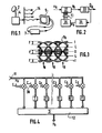
- the system of Figure 1 is described using digital signals encoded in duobinary, but it is obvious that the invention is applicable also with any signal encoded on several levels.
- the D2-MAC / packet signal received on an antenna 2 is retransmitted in amplitude modulation (modulation carried out in a distribution center 4) by a cable distribution network 14, to one or more televisions, one of which is shown in 5.
- Amplitude modulation with reduced sideband is used, which offers the advantage of occupying less space, for the same bandwidth of the modulating signal, than amplitude modulation with double band. Unfortunately, it can give rise to intersymbol interference if certain parameters of the transmission chain and of the demodulation do not respect the theoretical principles.
- the D2-MAC / packet signal is recovered in baseband on the scart socket of amplitude modulation receiver 5 and with reduced sideband (so-called videocomposite output).
- the signals are processed, in order to be decoded there, in element 7 and the image signals decoded, with the sound signals and the synchronization signals are returned to the terminals of the aforesaid SCART socket.
- the signal to be corrected by the equalizer of the invention is the duobinary part of the time multiplex of the D2-MAC / packet signal.
- the equalizer is therefore located in element 7 upstream of the duobinary data decoding circuit; it is preceded by an analog / digital converter.
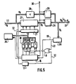
- the input signal Xk (k is the time index of the sample) is brought to a transverse digital filter 27.
- the filtered signal y k which leaves it is brought to a threshold comparator 33 in which the signal y k is compared with two thresholds L placed at mid-amplitude of each of the polarities of the "eye diagram" of the received signal (FIG. 3), and the result of the comparison makes it possible to decide on the normalized value (low, zero, high) to assign to the signal.
- the "decided" signal â k is the useful signal. It is brought to an element 34 which calculates the error, called e k , for each sample.
- This error is the difference between the "decided" signal which has a normalized amplitude, and the filtered signal y k .
- the error e k is supplied to an automaton 35.
- the latter adapts the coefficients of the filter in order to reduce the mean square error. It provides the filter with the N coefficients c; adapted.
- the sequence of symbols is known and the receiver has the sequence, which is compared with the decided signal: there is no estimation to be made on the received signal.
- This device works on strong distortions, but synchronization is difficult to achieve.
- the received signal is estimated. This estimate serves as a reference signal. This device works on any information. There is no sequence memorization. Usually, the corresponding algorithms provide for a learning phase.
- the disruptor is unknown; the third case is therefore excluded.
- the first case requires permanent storage of the sequence information in the receiver. It is therefore self-adaptive filtering that is most appropriate here. Furthermore, the present transmission system does not introduce large distortions, and the learning phase is not even necessary.
- two main optimization criteria can be used, namely: either obtain the minimum of the maximum distortion, or obtain the minimum of the mean square error.
- the duobinary signal is brought in digital form on an eight-wire bus 11.
- the signal x k is expressed, not in natural binary, but in signed binary (two's complement): the bus 11 therefore has seven value wires and a sign wire.
- the signal x k is brought to the digital filter 27 which is constituted according to the diagram in FIG. 4. Its output signal y k passes through an element 26 which is a switch register.
- the input signal x k is also supplied to a delay element 28 intended to supply a signal identical to the input signal but delayed by the number R of clock periods desired to be in synchronism with the signal from the filter 27. This delayed signal ( Xk . R ) is supplied to a register 29.
- the output signal 31 is taken as desired from the register 29 (x k . R not filtered) or from the register 26 (y k filtered). This signal is brought to an element 36 which directly determines the sign of the error sgn (e k ). It does not use a threshold comparator strictly speaking (the comparator 33 was mentioned above to simplify the explanations), but contains a read only memory (PROM) whose role will be explained now. For a determined value of the signal y k , it is easy to determine both â k and e k . To illustrate this, a value y k is indicated by way of example in FIG. 3. Its value is greater than the highest threshold L: therefore â k is 1.
- the sign of the error is positive.
- the value of y k is entered into the PROM memory as an address, and for each address has been written in advance the corresponding value sgn (e k ).
- This value is delivered on a wire 22.
- This wire 22 as well as the sign wire 32 carrying the sign of x k (and which is taken from the bus 11) are connected to the inputs of an exclusive OR gate 9.
- the wire 32 further passes through a delay element 17, so that the sign brought to the door 9 becomes that of the sample x k . ,, instead of that of the sample x k .
- the counters which correspond to the coefficients to be adjusted count in signed binary with a capacity of ⁇ 2 7 , ie +128, that is to say their capacity expressed in bits is equal to the number of bits for quantizing the coefficients of the filter.
- the increment or decrement of a unit represents a variation of one hundred and twenty-eighth of the maximum value, which therefore amounts to adding or subtracting a.
- D2-MAC / packet signal decoders work with a sample rate of 20.25 Mhz while the bit rate of the duobinary period in D2-MAC / packet is 10.125 Mhz: when using a signal supplied by such a decoder, only one out of two samples is processed in this device.
- a clock signal H at 10.125 Mhz in phase with the bellies of the eye diagram (FIG. 3), which is generated from the above-mentioned decoder, is supplied to all the elements of this device and in particular to element 36 to trigger the reading of sgn- (e k ). It is also brought to a management unit 16 which is connected to the counters and to the register 21.
- This body is used in particular to designate the counter which must operate at a given instant, by means of the authorization input ("enable") of the last.
- the counters each operate in turn at the rate of the clock, so that the value of i in x k . ; be the right one every time.
- the management unit 16 still waits eight periods d 'clock, so that the effect of the modification of the coefficients is complete at the output of the filter then at the output of element 36 (the total transit time is approximately eight clock periods), and it then triggers a new self-adjustment cycle of coefficients, if applicable.
- All the elements or organs 16, 38-45, 21 thus constitute an automaton for carrying out the process of self-adaptation of the coefficients of the filter.
- windows F which constitute a set composed of three windows F, one framing the normal level of a zero sample, another framing the normal level of a high sample (1), and the third framing the normal level of a low sample (-1). It is clear that for each value of y k , whether or not it is included in one of the windows F depends only on said value of y k .
- element 36 contains in a PROM memory, for each address corresponding to a value of y k , the sign of e k : in addition, a code is recorded at each address indicating whether the value of y k is included in one of the windows of the set of windows F.
- the element 36 is thus a decision element which supplies said code via a wire 19 to the member 16, so that the latter stops the incrementation counters, ie the self-adaptation of the coefficients, when a value of y k has been found in one of the windows.
- a single value of y k found in one of the windows is enough to cause the process to stop, which is then kept stopped until a value of y k is again found outside the windows.
- the main filter coefficient is excluded from the self-adaptation process and kept at ONE permanently.
- the auto-adaptive filter must behave at the start, and at least until the clock synchronization has been established by the D2-MAC / packet signal decoder, like an all-pass filter. After this synchronization has been established, a signal corresponding to the duration of the duobinary burst (10.5 / JS) is introduced on an input 30, to be supplied to the registers 29, 26 and to the management unit 16. A From this signal, the organ 16 activates the self-adaptation process during this period (10.5 / JS), then stops it during the rest of the television line (53.5 us).
- the signal 30 is also brought to registers 26 and 29, to put the output of one in a high impedance state while using the output of the other and vice versa, so as to choose the signal filtered during the duobinary signal period and the unfiltered signal during the rest of the TV line.
- an unfiltered signal is used, because the sampling is done there at 20.25 MHz, while the operation of the filter is provided at 10.125 MHz, for theoretical reasons; with a few modifications, it could nevertheless be envisaged to filter a sample from two of the MAC components during this rest of the line, leaving the filter therefore still in service.
- the equalizer When the equalizer is initialized, all the coefficients have a value of zero in the counters. Although the main filter coefficient is kept at ONE permanently, with certain types of digital filters it is nevertheless necessary to initialize it. To this end, the management member 16 is connected to an element 20 which, during initialization, transfers the value UN from a register to the counter which corresponds to the main coefficient. With other types of filter, the main coefficient could be permanently wired to ONE.
- the present device could also be used with DMAC or high definition signals, however with some modifications.
Landscapes
- Engineering & Computer Science (AREA)
- Multimedia (AREA)
- Signal Processing (AREA)
- Power Engineering (AREA)
- Filters That Use Time-Delay Elements (AREA)
- Cable Transmission Systems, Equalization Of Radio And Reduction Of Echo (AREA)
- Compression Or Coding Systems Of Tv Signals (AREA)
- Picture Signal Circuits (AREA)
Applications Claiming Priority (2)
| Application Number | Priority Date | Filing Date | Title |
|---|---|---|---|
| FR8908797 | 1989-06-30 | ||
| FR8908797A FR2649273B1 (fr) | 1989-06-30 | 1989-06-30 | Dispositif d'egalisation autoadaptative pour des echantillons numeriques codes en duobinaire |
Publications (1)
| Publication Number | Publication Date |
|---|---|
| EP0405679A1 true EP0405679A1 (de) | 1991-01-02 |
Family
ID=9383326
Family Applications (1)
| Application Number | Title | Priority Date | Filing Date |
|---|---|---|---|
| EP90201663A Ceased EP0405679A1 (de) | 1989-06-30 | 1990-06-25 | Einrichtung zur autoadaptiven Entzerrung von duobinär kodierten digitalen Signalmustern |
Country Status (3)
| Country | Link |
|---|---|
| EP (1) | EP0405679A1 (de) |
| JP (1) | JPH03101515A (de) |
| FR (1) | FR2649273B1 (de) |
Cited By (1)
| Publication number | Priority date | Publication date | Assignee | Title |
|---|---|---|---|---|
| EP0923204A3 (de) * | 1997-12-11 | 2000-12-06 | Alcatel | Optischer Empfänger für den empfang von digital übertragenen Daten |
Families Citing this family (1)
| Publication number | Priority date | Publication date | Assignee | Title |
|---|---|---|---|---|
| US4985254A (en) * | 1987-11-06 | 1991-01-15 | Nippon Zoki Pharmaceutical Co., Ltd. | Method of treating ischemic diseases |
Citations (2)
| Publication number | Priority date | Publication date | Assignee | Title |
|---|---|---|---|---|
| EP0169093A1 (de) * | 1984-06-04 | 1986-01-22 | ETAT FRANCAIS repr. par le Secrétaire d'Etat aux Postes et Télécomm. et à la Télédiffusion (CENT. NAT. D'ETUDES DES TELECOMM.) | Empfänger für Fernsehzeitmultiplexübertragung mit einem Frequenzdemodulator |
| EP0308776A2 (de) * | 1987-09-25 | 1989-03-29 | Nippon Hoso Kyokai | Dekodierender Entzerrer |
-
1989
- 1989-06-30 FR FR8908797A patent/FR2649273B1/fr not_active Expired - Fee Related
-
1990
- 1990-06-25 EP EP90201663A patent/EP0405679A1/de not_active Ceased
- 1990-06-30 JP JP2171386A patent/JPH03101515A/ja active Pending
Patent Citations (2)
| Publication number | Priority date | Publication date | Assignee | Title |
|---|---|---|---|---|
| EP0169093A1 (de) * | 1984-06-04 | 1986-01-22 | ETAT FRANCAIS repr. par le Secrétaire d'Etat aux Postes et Télécomm. et à la Télédiffusion (CENT. NAT. D'ETUDES DES TELECOMM.) | Empfänger für Fernsehzeitmultiplexübertragung mit einem Frequenzdemodulator |
| EP0308776A2 (de) * | 1987-09-25 | 1989-03-29 | Nippon Hoso Kyokai | Dekodierender Entzerrer |
Non-Patent Citations (1)
| Title |
|---|
| IEEE TRANSACTIONS ON COMMUNICATION TECHNOLOGY * |
Cited By (2)
| Publication number | Priority date | Publication date | Assignee | Title |
|---|---|---|---|---|
| EP0923204A3 (de) * | 1997-12-11 | 2000-12-06 | Alcatel | Optischer Empfänger für den empfang von digital übertragenen Daten |
| US6295152B1 (en) | 1997-12-11 | 2001-09-25 | Alcatel | Optical receiver for receiving digitally transmitted data |
Also Published As
| Publication number | Publication date |
|---|---|
| FR2649273B1 (fr) | 1991-09-13 |
| JPH03101515A (ja) | 1991-04-26 |
| FR2649273A1 (fr) | 1991-01-04 |
Similar Documents
| Publication | Publication Date | Title |
|---|---|---|
| FR2623669A1 (fr) | Appareil et procede d'egalisation pour la transmission de donnees | |
| CA1173965A (fr) | Procede et dispositif de detection de la sequence d'apprentissage d'un egaliseur autoadaptatif | |
| FR2602944A1 (fr) | Ensemble d'abonne pour telephonie numerique sans fil; modem et dispositifs divers (synthetiseur de frequence...) pour cet ensemble | |
| FR2615675A1 (fr) | Procede de demodulation de signaux modules numeriquement et dispositif de mise en oeuvre d'un tel procede | |
| FR2566604A1 (fr) | Recepteur de donnees enregistrees | |
| EP0576359B1 (de) | Verfahren und Einrichtung zur entscheidungsrückgekoppelten Entzerrung für die blockweise Übertragung von Informationssymbolen | |
| EP3506174B1 (de) | System zur demodulation oder blindsuche der eigenschaften von digitalen telekommunikationssignalen | |
| FR2524742A1 (fr) | Procede de transmission de donnees en duplex sur un circuit telephonique commute et modem correspondant | |
| EP0409756B1 (de) | Datenempfangsanlage mit verzögerter Entzerrung und retroaktiver Taktwiedergewinnung | |
| FR2468258A1 (fr) | Circuit de correction des bruits de phase pour un systeme de transmission | |
| EP0524597B1 (de) | Iteratives Verfahren zur Verminderung von Nachbarsymbolstörungen, sowie entsprechende Empfangsvorrichtung und Anwendung | |
| CA1137177A (fr) | Procede de reduction des bruits de phase a la reception d'une transmission de donnees | |
| EP0405679A1 (de) | Einrichtung zur autoadaptiven Entzerrung von duobinär kodierten digitalen Signalmustern | |
| EP0169093A1 (de) | Empfänger für Fernsehzeitmultiplexübertragung mit einem Frequenzdemodulator | |
| EP0127544B1 (de) | Echokompensator mit einem adaptiven digitalen Filter für ein Übertragungssystem | |
| EP0098198A2 (de) | Verfahren und Einrichtung zur Kompression der Datenrate von Daten, welche zwischen mindestens einem Sender und einem Empfänger von Fernsehbildern übertragen werden | |
| EP0411526B1 (de) | Einrichtung zur Korrektur der Übertragungsverzerrungen eines Datensignals in Abhängigkeit von Übertragungskodeverletzungen | |
| FR3067541A1 (fr) | Emission et reception d'un flux de donnees | |
| EP0434584B1 (de) | Vorrichtung zur Entzerrung von linearen und nichtlinearen Störungen eines durch einen verzerrten Kanal empfangenen Signals | |
| EP0348322B1 (de) | Verfahren zur Auswertung des Gleichstrompegels eines Signals nach der DMAC-Paket-Norm, entsprechende Vorrichtung und Benutzung | |
| EP0328461B1 (de) | Verfahren zur Sendung eines Fernsehprogramms mit hoher Auflösung und Empfänger mit Entzerrer, um ein solches Programm zu empfangen | |
| EP1438815B1 (de) | Zwischensymbolstörungslöscher | |
| EP0368417B1 (de) | Anordnung mit einer verbesserten Gleichstrompegelauswertungsvorrichtung | |
| FR2710219A1 (fr) | Dispositif de récupération du rythme d'horloge et modem comportant un tel dispositif. | |
| EP1107528A1 (de) | Verfahren der Erkennung von Blöcken für einen Schwindendenkanal |
Legal Events
| Date | Code | Title | Description |
|---|---|---|---|
| PUAI | Public reference made under article 153(3) epc to a published international application that has entered the european phase |
Free format text: ORIGINAL CODE: 0009012 |
|
| AK | Designated contracting states |
Kind code of ref document: A1 Designated state(s): DE FR GB IT |
|
| RAP1 | Party data changed (applicant data changed or rights of an application transferred) |
Owner name: N.V. PHILIPS' GLOEILAMPENFABRIEKEN Owner name: PHILIPS ELECTRONIQUE GRAND PUBLIC |
|
| 17P | Request for examination filed |
Effective date: 19910627 |
|
| 17Q | First examination report despatched |
Effective date: 19930609 |
|
| STAA | Information on the status of an ep patent application or granted ep patent |
Free format text: STATUS: THE APPLICATION HAS BEEN REFUSED |
|
| 18R | Application refused |
Effective date: 19941023 |