EP0406078A1 - Zweiaktmotor mit Drehschiebern und Betrieb dieses Motors - Google Patents
Zweiaktmotor mit Drehschiebern und Betrieb dieses Motors Download PDFInfo
- Publication number
- EP0406078A1 EP0406078A1 EP90401785A EP90401785A EP0406078A1 EP 0406078 A1 EP0406078 A1 EP 0406078A1 EP 90401785 A EP90401785 A EP 90401785A EP 90401785 A EP90401785 A EP 90401785A EP 0406078 A1 EP0406078 A1 EP 0406078A1
- Authority
- EP
- European Patent Office
- Prior art keywords
- combustion chamber
- engine
- cylinder
- circuit
- plug
- Prior art date
- Legal status (The legal status is an assumption and is not a legal conclusion. Google has not performed a legal analysis and makes no representation as to the accuracy of the status listed.)
- Granted
Links
- 238000002485 combustion reaction Methods 0.000 claims abstract description 28
- 230000006835 compression Effects 0.000 claims abstract description 13
- 238000007906 compression Methods 0.000 claims abstract description 13
- 239000012530 fluid Substances 0.000 claims abstract description 6
- 239000000446 fuel Substances 0.000 claims description 22
- 239000007789 gas Substances 0.000 claims description 18
- 238000002347 injection Methods 0.000 claims description 12
- 239000007924 injection Substances 0.000 claims description 12
- 239000007788 liquid Substances 0.000 claims description 4
- 239000000203 mixture Substances 0.000 description 9
- 238000010408 sweeping Methods 0.000 description 3
- 230000009466 transformation Effects 0.000 description 3
- 230000007423 decrease Effects 0.000 description 2
- 238000010586 diagram Methods 0.000 description 2
- 238000009826 distribution Methods 0.000 description 2
- 238000001816 cooling Methods 0.000 description 1
- 125000004122 cyclic group Chemical group 0.000 description 1
- 230000003111 delayed effect Effects 0.000 description 1
- 238000007789 sealing Methods 0.000 description 1
- 239000000243 solution Substances 0.000 description 1
- 238000011144 upstream manufacturing Methods 0.000 description 1
Images

Classifications
-
- F—MECHANICAL ENGINEERING; LIGHTING; HEATING; WEAPONS; BLASTING
- F02—COMBUSTION ENGINES; HOT-GAS OR COMBUSTION-PRODUCT ENGINE PLANTS
- F02B—INTERNAL-COMBUSTION PISTON ENGINES; COMBUSTION ENGINES IN GENERAL
- F02B33/00—Engines characterised by provision of pumps for charging or scavenging
- F02B33/32—Engines with pumps other than of reciprocating-piston type
- F02B33/34—Engines with pumps other than of reciprocating-piston type with rotary pumps
-
- F—MECHANICAL ENGINEERING; LIGHTING; HEATING; WEAPONS; BLASTING
- F01—MACHINES OR ENGINES IN GENERAL; ENGINE PLANTS IN GENERAL; STEAM ENGINES
- F01L—CYCLICALLY OPERATING VALVES FOR MACHINES OR ENGINES
- F01L7/00—Rotary or oscillatory slide valve-gear or valve arrangements
- F01L7/02—Rotary or oscillatory slide valve-gear or valve arrangements with cylindrical, sleeve, or part-annularly shaped valves
- F01L7/026—Rotary or oscillatory slide valve-gear or valve arrangements with cylindrical, sleeve, or part-annularly shaped valves with two or more rotary valves, their rotational axes being parallel, e.g. 4-stroke
-
- F—MECHANICAL ENGINEERING; LIGHTING; HEATING; WEAPONS; BLASTING
- F01—MACHINES OR ENGINES IN GENERAL; ENGINE PLANTS IN GENERAL; STEAM ENGINES
- F01L—CYCLICALLY OPERATING VALVES FOR MACHINES OR ENGINES
- F01L7/00—Rotary or oscillatory slide valve-gear or valve arrangements
- F01L7/12—Rotary or oscillatory slide valve-gear or valve arrangements specially for two-stroke engines
-
- F—MECHANICAL ENGINEERING; LIGHTING; HEATING; WEAPONS; BLASTING
- F02—COMBUSTION ENGINES; HOT-GAS OR COMBUSTION-PRODUCT ENGINE PLANTS
- F02B—INTERNAL-COMBUSTION PISTON ENGINES; COMBUSTION ENGINES IN GENERAL
- F02B25/00—Engines characterised by using fresh charge for scavenging cylinders
- F02B25/14—Engines characterised by using fresh charge for scavenging cylinders using reverse-flow scavenging, e.g. with both outlet and inlet ports arranged near bottom of piston stroke
- F02B25/145—Engines characterised by using fresh charge for scavenging cylinders using reverse-flow scavenging, e.g. with both outlet and inlet ports arranged near bottom of piston stroke with intake and exhaust valves exclusively in the cylinder head
-
- F—MECHANICAL ENGINEERING; LIGHTING; HEATING; WEAPONS; BLASTING
- F02—COMBUSTION ENGINES; HOT-GAS OR COMBUSTION-PRODUCT ENGINE PLANTS
- F02B—INTERNAL-COMBUSTION PISTON ENGINES; COMBUSTION ENGINES IN GENERAL
- F02B1/00—Engines characterised by fuel-air mixture compression
- F02B1/02—Engines characterised by fuel-air mixture compression with positive ignition
- F02B1/04—Engines characterised by fuel-air mixture compression with positive ignition with fuel-air mixture admission into cylinder
-
- F—MECHANICAL ENGINEERING; LIGHTING; HEATING; WEAPONS; BLASTING
- F02—COMBUSTION ENGINES; HOT-GAS OR COMBUSTION-PRODUCT ENGINE PLANTS
- F02B—INTERNAL-COMBUSTION PISTON ENGINES; COMBUSTION ENGINES IN GENERAL
- F02B75/00—Other engines
- F02B75/02—Engines characterised by their cycles, e.g. six-stroke
- F02B2075/022—Engines characterised by their cycles, e.g. six-stroke having less than six strokes per cycle
- F02B2075/025—Engines characterised by their cycles, e.g. six-stroke having less than six strokes per cycle two
-
- F—MECHANICAL ENGINEERING; LIGHTING; HEATING; WEAPONS; BLASTING
- F02—COMBUSTION ENGINES; HOT-GAS OR COMBUSTION-PRODUCT ENGINE PLANTS
- F02B—INTERNAL-COMBUSTION PISTON ENGINES; COMBUSTION ENGINES IN GENERAL
- F02B75/00—Other engines
- F02B75/02—Engines characterised by their cycles, e.g. six-stroke
- F02B2075/022—Engines characterised by their cycles, e.g. six-stroke having less than six strokes per cycle
- F02B2075/027—Engines characterised by their cycles, e.g. six-stroke having less than six strokes per cycle four
-
- F—MECHANICAL ENGINEERING; LIGHTING; HEATING; WEAPONS; BLASTING
- F02—COMBUSTION ENGINES; HOT-GAS OR COMBUSTION-PRODUCT ENGINE PLANTS
- F02B—INTERNAL-COMBUSTION PISTON ENGINES; COMBUSTION ENGINES IN GENERAL
- F02B75/00—Other engines
- F02B75/12—Other methods of operation
- F02B2075/125—Direct injection in the combustion chamber for spark ignition engines, i.e. not in pre-combustion chamber
-
- F—MECHANICAL ENGINEERING; LIGHTING; HEATING; WEAPONS; BLASTING
- F02—COMBUSTION ENGINES; HOT-GAS OR COMBUSTION-PRODUCT ENGINE PLANTS
- F02B—INTERNAL-COMBUSTION PISTON ENGINES; COMBUSTION ENGINES IN GENERAL
- F02B3/00—Engines characterised by air compression and subsequent fuel addition
- F02B3/06—Engines characterised by air compression and subsequent fuel addition with compression ignition
-
- Y—GENERAL TAGGING OF NEW TECHNOLOGICAL DEVELOPMENTS; GENERAL TAGGING OF CROSS-SECTIONAL TECHNOLOGIES SPANNING OVER SEVERAL SECTIONS OF THE IPC; TECHNICAL SUBJECTS COVERED BY FORMER USPC CROSS-REFERENCE ART COLLECTIONS [XRACs] AND DIGESTS
- Y02—TECHNOLOGIES OR APPLICATIONS FOR MITIGATION OR ADAPTATION AGAINST CLIMATE CHANGE
- Y02T—CLIMATE CHANGE MITIGATION TECHNOLOGIES RELATED TO TRANSPORTATION
- Y02T10/00—Road transport of goods or passengers
- Y02T10/10—Internal combustion engine [ICE] based vehicles
- Y02T10/12—Improving ICE efficiencies
Definitions
- the present invention relates to a two-stroke engine, the distribution of which is ensured in particular by rotary or rotary plugs.
- Fuel can be supplied by direct injection into the cylinder, by pneumatic or liquid injection.
- the engine can be gasoline or diesel and can be used to motorize motor vehicles.
- the device according to the invention is applicable for the transformation of a four-stroke engine into a two-stroke engine.
- One of the problems encountered in particular in such a transformation is the limitation in speed of the valve distributions for which the critical speed is quickly reached, since, for such a transformation, at equal engine speed (crankshaft), the valves are subjected in a two-stroke engine, to operating frequencies double those to which they are subjected in a four-stroke engine.
- certain embodiments according to the present invention make it possible to reduce the losses through the fuel mixture exhaust pipe during the sweeping phase.
- the present invention relates to a two-stroke engine comprising at least one cylinder having a combustion chamber, an exhaust duct connected to said combustion chamber, at least one inlet duct for a fresh compressed gas and means to supply said compressed fresh gas.
- this engine comprises in combination at least a first rotary valve for the opening and closing of said exhaust duct and at least a second rotary valve for the introduction of fluid into said combustion chamber.
- the second bushel can be connected to the compression means and the fluid can correspond to the compressed fresh gases.
- the engine may include a high pressure liquid injector.
- the engine may include a pneumatic injection device, possibly controlled by a solenoid.
- the engine according to the invention may include fuel injection or metering means and the second bushel may have two passages, the first of which may be connected to the compression means through a first circuit and the second of which is connected to the means compression by a second circuit comprising the fuel injection or metering means.
- the opening of the second passage in the combustion chamber may take place later than that of the first passage.
- the second bushel may be connected to the compression means by a first circuit comprising fuel supply means, and the engine may further comprise a second circuit for supplying the cylinder with non-fueled fresh gas.
- This second circuit can connect the compression means to a light provided on the walls of the cylinder at the bottom of the combustion chamber.
- the second circuit may include a means of winnowing.
- At least one of the bushels may be housed in the upper part of the combustion chamber, in particular in the cylinder head.
- the first bushel may have two passages.
- the engine according to the invention can be a petrol or diesel engine, that is to say, powered by gas oil.
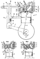
- FIG. 1 represents a cylinder 1 of an engine according to the invention.
- This engine comprises a cylinder head 2, a piston 3 and a connecting rod-crank system 4.
- Reference 5 designates the exhaust pipe.
- the reference 6 designates a rotating bushel placed at the exhaust of the cylinder 1.
- This bushel has a passage 7 which periodically relates the combustion chamber 8 and the exhaust pipe 5 when it is necessary to evacuate the burnt gases from the chamber combustion 8.
- This engine comprises an external mechanical compressor 9 driven from the crankshaft 10 by drive means 11, such as a belt.
- This compressor is supplied with air by the line 12 through an air filter 13.
- the line 14 is used to supply the combustion chamber 8 with fresh gas, this line may include means 15 for cooling the fresh gases after compression.
- the supply of fresh air to the combustion chamber 8 is done by a rotary plug 16 connected to the pipe 14.
- This plug has a passage 17.
- This passage 17 can be profiled to facilitate fluid flow and avoid sudden changes in direction of flow.
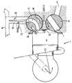
- the intake valve 16 can have a shape designed to introduce air by orienting it first towards the wall 22, then more and more towards the middle of the combustion chamber 18 and thus create a loop as shown in Figure 2 by arrows 23.
- the rotary or rotary plugs 6 and 16 are housed in the cylinder head 2.
- the rotary plugs are rotated from the crankshaft 10, for example, by a timing chain or a toothed belt.
- the pipes 12 and 14 can be connected by a bypass 18 controlled by a flap 19.
- This pipe is shown in dotted lines.
- FIG. 1 represents the instant of the cycle corresponding to the start of the opening of the exhaust valve 6 which is done in advance with respect to the opening of the intake valve 16.
- the arrows 20 indicate the direction of rotation of the rotary plugs and the arrow 21 the direction of rotation of the crankshaft.
- the arrows 24 represent the exhaust gases which leave the combustion chamber 8.
- Figure 2 shows the same engine as Figure 1, while the piston is in bottom dead center. This corresponds to the scanning phase of the combustion chamber. The scanning is illustrated by the arrows 23.
- FIG. 3 represents the cylinder 1, exhaust closed and at the end of the intake phase.
- two fuel supply systems have been shown, but it should be noted that one of these systems excludes the other.
- the first system performs direct injection into the combustion chamber 8 by a high pressure injector 24.
- this injector and its feed pump deliver a jet at a pressure of between 50 and 100 bars for a gasoline engine and a few hundred bars for a diesel engine.
- a pneumatic injection can also be carried out directly in the combustion chamber, in particular with an introduction pressure under a pressure typically between 2 and 10 bars.
- the fuel is delivered by an injector or metering means upstream of the combustion chamber 8 and of the plug 16. This injection can be done in the line 14, or better in an auxiliary line 25.
- the plug 16 has a double passage and comprises, in addition to passage 17, a passage 26.
- the passage 26 performs a delayed admission with respect to the passage 17.
- a double introduction is made by the plug 16 (Fig. 3), one being produced by the passage 17, shortly after the start of the exhaust, with compressed air alone for sweeping and filling the cylinder 8 while the other introduction which is carried out by passage 26 is offset in the cycle for introduction of the pneumatic fuel mixture.
- a valve 28 (Fig. 3A) may be provided to adjust the flow of pure air to the fuel mixture and for example preferably reduce it when the engine load decreases.
- the exhaust valve can comprise two passages providing exhaust openings offset in the cycle.
- the passages of these bushels may be connected at the outlet to two conduits, one of which could be opened or closed by a valve-making device not shown. This would result in the simple possibility of having two different exhaust opening diagrams to choose according to the load and speed conditions.
- the exhaust passages are preferably calibrated asymmetrically relative to the bottom dead center (PMB) and the angular amplitude of their opening is greater before the PMB than after.
- FIG. 4 shows another embodiment.
- the embodiment of Figure 4 differs from that of Figure 1 in that the cylinder 1 has at least one light 29 controlled by the piston 3 and connected by a pipe 30 to the inlet duct 14 of compressed air.
- This pipe 30 allows the cylinder 1 to be swept and filled.
- the inlet valve 16 serves to control the introduction of the air / fuel mixture obtained by pneumatic injection. This injection is obtained by an injector or fuel metering means 31 which delivers the fuel into the auxiliary duct 32.
- the intake of pure air or fresh gas through the light 29 can be controlled by a valve 33 when the load decreases and can even be completely closed.
- the cylinder is then supplied only with the fuel mixture passing through the plug 16 (Fig. 4).
- Figure 5 shows the cylinder while the lumen 29 is open and the plug 16 does not yet allow the passage of the fuel mixture.
- the arrows 34 represent the sweeping and filling of the cylinder or combustion chamber 8.
- the exhaust 5 opens first (Fig. 1).
- the piston continues its downward stroke. Admission by bushel of fresh gas only (non-fuel) then occurs.
- This gas is introduced under pressure through a valve 16 (Fig. 1) or a light 29 (Fig. 4).
- a valve 16 Fig. 1
- a light 29 Fig. 4
- the opening diagram will be almost symmetrical. The introduction of this air makes it possible to sweep the cylinder by expelling the burnt gases towards the exhaust, as shown in FIGS. 2 and 5. Then, this air participates in the filling of the cylinder particularly after closing the exhaust.
- the fuel is preferably introduced after the exhaust has been closed (which can possibly start at vicinity thereof).
- the pneumatic mixture introduction is formed by compressed air supplied by the compressor and fuel metered by a cyclic metering device, - through a pneumatic injector comprising a small valve controlled by solenoid, or by another mechanically controlled means (Figs 1 to 3), - through a high pressure liquid injector (Figs 1 to 3).
- a pneumatic injector comprising a small valve controlled by solenoid, or by another mechanically controlled means (Figs 1 to 3)
- Figs 1 to 3 a high pressure liquid injector
- the plugs according to the invention may be fitted with a sealing system with respect to the combustion chamber.
- This system could be such as those described in patents FR-2,531,174 or FR-2,123,968.
Landscapes
- Engineering & Computer Science (AREA)
- Mechanical Engineering (AREA)
- General Engineering & Computer Science (AREA)
- Chemical & Material Sciences (AREA)
- Combustion & Propulsion (AREA)
- Output Control And Ontrol Of Special Type Engine (AREA)
- Combustion Methods Of Internal-Combustion Engines (AREA)
- Transmission Devices (AREA)
- Fuel-Injection Apparatus (AREA)
Priority Applications (1)
| Application Number | Priority Date | Filing Date | Title |
|---|---|---|---|
| AT90401785T ATE97993T1 (de) | 1989-06-30 | 1990-06-22 | Zweiaktmotor mit drehschiebern und betrieb dieses motors. |
Applications Claiming Priority (2)
| Application Number | Priority Date | Filing Date | Title |
|---|---|---|---|
| FR8908853A FR2649156B1 (fr) | 1989-06-30 | 1989-06-30 | Moteur deux temps a boisseaux tournants et utilisations d'un tel moteur |
| FR8908853 | 1989-06-30 |
Publications (2)
| Publication Number | Publication Date |
|---|---|
| EP0406078A1 true EP0406078A1 (de) | 1991-01-02 |
| EP0406078B1 EP0406078B1 (de) | 1993-12-01 |
Family
ID=9383367
Family Applications (1)
| Application Number | Title | Priority Date | Filing Date |
|---|---|---|---|
| EP90401785A Expired - Lifetime EP0406078B1 (de) | 1989-06-30 | 1990-06-22 | Zweiaktmotor mit Drehschiebern und Betrieb dieses Motors |
Country Status (5)
| Country | Link |
|---|---|
| EP (1) | EP0406078B1 (de) |
| JP (1) | JPH0347423A (de) |
| AT (1) | ATE97993T1 (de) |
| DE (1) | DE69004874T2 (de) |
| FR (1) | FR2649156B1 (de) |
Cited By (2)
| Publication number | Priority date | Publication date | Assignee | Title |
|---|---|---|---|---|
| FR2678319A1 (fr) * | 1991-06-25 | 1992-12-31 | Inst Francais Du Petrole | Systeme d'aide a la pulverisation d'un melange carbure dans une chambre de combustion et application du systeme a un moteur a combustion interne. |
| EP0577451A1 (de) * | 1992-07-02 | 1994-01-05 | Institut Français du Pétrole | Vorrichtung zum Kontrollieren der pneumatischen Einspritzung eines Gemisches für eine Zweitaktbrennkraftmaschine und ihre Verwendung |
Families Citing this family (2)
| Publication number | Priority date | Publication date | Assignee | Title |
|---|---|---|---|---|
| JPH07102918A (ja) * | 1993-10-01 | 1995-04-18 | Goro Urushiyama | エンジン用シリンダヘッド |
| JP2010091581A (ja) * | 2009-12-18 | 2010-04-22 | Yukifumi Nakamura | 低圧電気設備の漏電電流状態を測定する装置 |
Citations (3)
| Publication number | Priority date | Publication date | Assignee | Title |
|---|---|---|---|---|
| EP0099873A2 (de) * | 1982-07-19 | 1984-02-01 | Josef V. Illichmann | Zylindrischer Drehschieber mit Abdichtung für Kolbenmotoren |
| EP0100713A1 (de) * | 1982-07-27 | 1984-02-15 | Guy Negre | Dichtungselement für eine Gaszyklus-Regelvorrichtung einer Brennkammer |
| DE3515262A1 (de) * | 1984-06-20 | 1986-01-09 | Frank 4330 Mülheim Warzecha | Drehschieber |
Family Cites Families (3)
| Publication number | Priority date | Publication date | Assignee | Title |
|---|---|---|---|---|
| FR940278A (fr) * | 1947-01-21 | 1948-12-08 | Moteur à combustion interne fonctionnant selon le cycle à deux temps | |
| FR2496757B1 (fr) * | 1980-12-22 | 1985-07-19 | Inst Francais Du Petrole | Dispositif pour alimenter en melange carbure un moteur deux temps avec introduction d'air a travers le carter |
| US4732124A (en) * | 1986-06-12 | 1988-03-22 | Toyota Jidosha Kabushiki Kaisha | Two-cycle internal combustion engine |
-
1989
- 1989-06-30 FR FR8908853A patent/FR2649156B1/fr not_active Expired - Lifetime
-
1990
- 1990-06-22 EP EP90401785A patent/EP0406078B1/de not_active Expired - Lifetime
- 1990-06-22 AT AT90401785T patent/ATE97993T1/de active
- 1990-06-22 DE DE90401785T patent/DE69004874T2/de not_active Expired - Fee Related
- 1990-06-30 JP JP2172540A patent/JPH0347423A/ja active Pending
Patent Citations (3)
| Publication number | Priority date | Publication date | Assignee | Title |
|---|---|---|---|---|
| EP0099873A2 (de) * | 1982-07-19 | 1984-02-01 | Josef V. Illichmann | Zylindrischer Drehschieber mit Abdichtung für Kolbenmotoren |
| EP0100713A1 (de) * | 1982-07-27 | 1984-02-15 | Guy Negre | Dichtungselement für eine Gaszyklus-Regelvorrichtung einer Brennkammer |
| DE3515262A1 (de) * | 1984-06-20 | 1986-01-09 | Frank 4330 Mülheim Warzecha | Drehschieber |
Cited By (4)
| Publication number | Priority date | Publication date | Assignee | Title |
|---|---|---|---|---|
| FR2678319A1 (fr) * | 1991-06-25 | 1992-12-31 | Inst Francais Du Petrole | Systeme d'aide a la pulverisation d'un melange carbure dans une chambre de combustion et application du systeme a un moteur a combustion interne. |
| EP0577451A1 (de) * | 1992-07-02 | 1994-01-05 | Institut Français du Pétrole | Vorrichtung zum Kontrollieren der pneumatischen Einspritzung eines Gemisches für eine Zweitaktbrennkraftmaschine und ihre Verwendung |
| FR2693233A1 (fr) * | 1992-07-02 | 1994-01-07 | Inst Francais Du Petrole | Dispositif de contrôle de l'injection pneumatique d'un mélange carbure dans un moteur à combustion interne à deux temps et utilisation associée. |
| US5419289A (en) * | 1992-07-02 | 1995-05-30 | Institut Francais Du Petrole | Device for controlling the pneumatic injection of a carbureted mixture in a two-stroke internal-combustion engine and associated utilization |
Also Published As
| Publication number | Publication date |
|---|---|
| FR2649156B1 (fr) | 1994-04-01 |
| ATE97993T1 (de) | 1993-12-15 |
| EP0406078B1 (de) | 1993-12-01 |
| DE69004874T2 (de) | 1994-04-07 |
| JPH0347423A (ja) | 1991-02-28 |
| FR2649156A1 (fr) | 1991-01-04 |
| DE69004874D1 (de) | 1994-01-13 |
Similar Documents
| Publication | Publication Date | Title |
|---|---|---|
| EP0421481B1 (de) | Einrichtung zum Einlass von Druckgasen in eine Brennkammer einer Brennkraftmaschine | |
| EP0296969B1 (de) | Vorrichtung zum Zuführen unter Druck von einem Gemisch in den Zylinder eines Motors | |
| FR2725475A1 (fr) | Moteur deux temps a injection pneumatique de melange carbure | |
| EP0346188B1 (de) | Vorrichtung und Verfahren für die Zufuhr von Druckluft Kraftstoff-Gemisch in den Zylinder einer Brennkraftmaschine | |
| EP0406078B1 (de) | Zweiaktmotor mit Drehschiebern und Betrieb dieses Motors | |
| EP0648314B1 (de) | Überwachungsvorrichtung und -verfahren der Verbrennung einer Viertaktbrennkraftmaschine | |
| EP0406083B1 (de) | Vorrichtung zur Steuerung des Einlassanfangs des unter Druck stehenden Gemisches für eine Brennkraftmaschine und deren Verwendung bei der Zweitaktmaschine | |
| EP0577451B1 (de) | Vorrichtung zum Kontrollieren der pneumatischen Einspritzung eines Gemisches für eine Zweitaktbrennkraftmaschine und ihre Verwendung | |
| FR2909718A1 (fr) | Moteur a combustion interne suralimente | |
| FR2477223A1 (fr) | Moteur a combustion interne a piston a mouvement alternatif | |
| EP0458670B1 (de) | Verfahren zur pneumatischen Kraftstoffeinpritzung in einen Zweitaktmotor und ein solcher Zweitaktmotor | |
| FR2575522A1 (fr) | Dispositif pour controler le jet de melange carbure delivre par un systeme d'injection pneumatique | |
| EP0507648B1 (de) | Zweitaktmotor mit selektiver Steuerung für die in der Brennkammer eingeführte Ladung | |
| FR2776708A1 (fr) | Nouveau moteur a combustion interne a quatre temps, allumage commande et injection directe | |
| CA1170520A (fr) | Dispositif de pompage et d'injection pour moteur a combustion interne | |
| EP0189714A1 (de) | Vorrichtung zum Verbessern der Qualität des von einem pneumatischen Einspritzsystem gelieferten Gemisches | |
| FR2496757A1 (fr) | Dispositif pour alimenter en melange carbure un moteur deux temps avec introduction d'air a travers le carter | |
| FR2853354A1 (fr) | Moteur a combustion interne a injection directe d'essence et a allumage commande | |
| FR2531139A1 (fr) | Dispositif de controle d'un circuit de gaz d'une chambre de combustion | |
| EP1387057A2 (de) | Zweitaktbrennkraftmaschine ohne Kurbelgehäusespülpumpe | |
| WO2001051786A1 (fr) | Procede et dispositif pour ameliorer le fonctionnement a bas regime des moteurs thermiques suralimentes | |
| FR2693507A1 (fr) | Procédé et dispositif d'alimentation d'un cylindre de moteur à combustion interne à deux temps. | |
| FR2866388A1 (fr) | Systeme de recirculation des gaz d'echappement d'un moteur a combustion interne | |
| FR3154769A1 (fr) | Dispositif d'injection pour un moteur à combustion interne | |
| FR2678319A1 (fr) | Systeme d'aide a la pulverisation d'un melange carbure dans une chambre de combustion et application du systeme a un moteur a combustion interne. |
Legal Events
| Date | Code | Title | Description |
|---|---|---|---|
| PUAI | Public reference made under article 153(3) epc to a published international application that has entered the european phase |
Free format text: ORIGINAL CODE: 0009012 |
|
| 17P | Request for examination filed |
Effective date: 19900710 |
|
| AK | Designated contracting states |
Kind code of ref document: A1 Designated state(s): AT BE DE GB IT SE |
|
| 17Q | First examination report despatched |
Effective date: 19920403 |
|
| ITF | It: translation for a ep patent filed | ||
| GRAA | (expected) grant |
Free format text: ORIGINAL CODE: 0009210 |
|
| AK | Designated contracting states |
Kind code of ref document: B1 Designated state(s): AT BE DE GB IT SE |
|
| REF | Corresponds to: |
Ref document number: 97993 Country of ref document: AT Date of ref document: 19931215 Kind code of ref document: T |
|
| GBT | Gb: translation of ep patent filed (gb section 77(6)(a)/1977) |
Effective date: 19931209 |
|
| REF | Corresponds to: |
Ref document number: 69004874 Country of ref document: DE Date of ref document: 19940113 |
|
| PLBE | No opposition filed within time limit |
Free format text: ORIGINAL CODE: 0009261 |
|
| STAA | Information on the status of an ep patent application or granted ep patent |
Free format text: STATUS: NO OPPOSITION FILED WITHIN TIME LIMIT |
|
| 26N | No opposition filed | ||
| EAL | Se: european patent in force in sweden |
Ref document number: 90401785.2 |
|
| PGFP | Annual fee paid to national office [announced via postgrant information from national office to epo] |
Ref country code: SE Payment date: 19960402 Year of fee payment: 7 |
|
| PGFP | Annual fee paid to national office [announced via postgrant information from national office to epo] |
Ref country code: AT Payment date: 19960417 Year of fee payment: 7 |
|
| PGFP | Annual fee paid to national office [announced via postgrant information from national office to epo] |
Ref country code: GB Payment date: 19960520 Year of fee payment: 7 |
|
| PGFP | Annual fee paid to national office [announced via postgrant information from national office to epo] |
Ref country code: BE Payment date: 19960612 Year of fee payment: 7 |
|
| PGFP | Annual fee paid to national office [announced via postgrant information from national office to epo] |
Ref country code: DE Payment date: 19960718 Year of fee payment: 7 |
|
| PG25 | Lapsed in a contracting state [announced via postgrant information from national office to epo] |
Ref country code: GB Free format text: LAPSE BECAUSE OF NON-PAYMENT OF DUE FEES Effective date: 19970622 Ref country code: AT Effective date: 19970622 |
|
| PG25 | Lapsed in a contracting state [announced via postgrant information from national office to epo] |
Ref country code: SE Effective date: 19970623 |
|
| PG25 | Lapsed in a contracting state [announced via postgrant information from national office to epo] |
Ref country code: BE Effective date: 19970630 |
|
| BERE | Be: lapsed |
Owner name: INSTITUT FRANCAIS DU PETROLE Effective date: 19970630 |
|
| GBPC | Gb: european patent ceased through non-payment of renewal fee |
Effective date: 19970622 |
|
| EUG | Se: european patent has lapsed |
Ref document number: 90401785.2 |
|
| PG25 | Lapsed in a contracting state [announced via postgrant information from national office to epo] |
Ref country code: DE Free format text: LAPSE BECAUSE OF NON-PAYMENT OF DUE FEES Effective date: 19980303 |
|
| PG25 | Lapsed in a contracting state [announced via postgrant information from national office to epo] |
Ref country code: IT Free format text: LAPSE BECAUSE OF NON-PAYMENT OF DUE FEES;WARNING: LAPSES OF ITALIAN PATENTS WITH EFFECTIVE DATE BEFORE 2007 MAY HAVE OCCURRED AT ANY TIME BEFORE 2007. THE CORRECT EFFECTIVE DATE MAY BE DIFFERENT FROM THE ONE RECORDED. Effective date: 20050622 |