EP0406092B1 - Vorrichtung zum Füllen von Behältern mit abgewogenen Mengen - Google Patents
Vorrichtung zum Füllen von Behältern mit abgewogenen Mengen Download PDFInfo
- Publication number
- EP0406092B1 EP0406092B1 EP90401807A EP90401807A EP0406092B1 EP 0406092 B1 EP0406092 B1 EP 0406092B1 EP 90401807 A EP90401807 A EP 90401807A EP 90401807 A EP90401807 A EP 90401807A EP 0406092 B1 EP0406092 B1 EP 0406092B1
- Authority
- EP
- European Patent Office
- Prior art keywords
- filling
- flow
- time
- control member
- spout
- Prior art date
- Legal status (The legal status is an assumption and is not a legal conclusion. Google has not performed a legal analysis and makes no representation as to the accuracy of the status listed.)
- Expired - Lifetime
Links
Images

Classifications
-
- B—PERFORMING OPERATIONS; TRANSPORTING
- B67—OPENING, CLOSING OR CLEANING BOTTLES, JARS OR SIMILAR CONTAINERS; LIQUID HANDLING
- B67C—CLEANING, FILLING WITH LIQUIDS OR SEMILIQUIDS, OR EMPTYING, OF BOTTLES, JARS, CANS, CASKS, BARRELS, OR SIMILAR CONTAINERS, NOT OTHERWISE PROVIDED FOR; FUNNELS
- B67C3/00—Bottling liquids or semiliquids; Filling jars or cans with liquids or semiliquids using bottling or like apparatus; Filling casks or barrels with liquids or semiliquids
- B67C3/02—Bottling liquids or semiliquids; Filling jars or cans with liquids or semiliquids using bottling or like apparatus
- B67C3/20—Bottling liquids or semiliquids; Filling jars or cans with liquids or semiliquids using bottling or like apparatus with provision for metering the liquids to be introduced, e.g. when adding syrups
- B67C3/202—Bottling liquids or semiliquids; Filling jars or cans with liquids or semiliquids using bottling or like apparatus with provision for metering the liquids to be introduced, e.g. when adding syrups by weighing
-
- B—PERFORMING OPERATIONS; TRANSPORTING
- B65—CONVEYING; PACKING; STORING; HANDLING THIN OR FILAMENTARY MATERIAL
- B65B—MACHINES, APPARATUS OR DEVICES FOR, OR METHODS OF, PACKAGING ARTICLES OR MATERIALS; UNPACKING
- B65B3/00—Packaging plastic material, semiliquids, liquids or mixed solids and liquids, in individual containers or receptacles, e.g. bags, sacks, boxes, cartons, cans, or jars
- B65B3/26—Methods or devices for controlling the quantity of the material fed or filled
- B65B3/28—Methods or devices for controlling the quantity of the material fed or filled by weighing
-
- G—PHYSICS
- G01—MEASURING; TESTING
- G01G—WEIGHING
- G01G13/00—Weighing apparatus with automatic feed or discharge for weighing-out batches of material
- G01G13/24—Weighing mechanism control arrangements for automatic feed or discharge
- G01G13/28—Weighing mechanism control arrangements for automatic feed or discharge involving variation of an electrical variable which is used to control loading or discharge of the receptacle
- G01G13/285—Weighing mechanism control arrangements for automatic feed or discharge involving variation of an electrical variable which is used to control loading or discharge of the receptacle involving comparison with a reference value
- G01G13/2851—Weighing mechanism control arrangements for automatic feed or discharge involving variation of an electrical variable which is used to control loading or discharge of the receptacle involving comparison with a reference value for controlling automatic loading of weigh pans or other receptacles
Definitions
- the present invention relates to a device for filling containers with weight dosing.
- Document EP 221.367 discloses a container filling device according to the preamble of claim 1 comprising a flow control member connected to a weight processing unit comprising a time measurement member associated with a weighing member for measuring a weight of product flowing for a determined time. This measurement is used to determine the opening of the flow control member in the filling phases following the phase where the weight measurement is carried out.
- the opening of the flow control member is constant during each filling phase so that if the weight measurement of the initial phase is distorted, the openings of the following phases will be correspondingly distorted.
- An object of the invention is to propose a device for filling containers with weight dosing which compensates for at least some of the disturbances resulting from transient regimes.
- a container filling device comprising a feed member connected to at least one filling spout via a flow control member connected to an output of a weight processing unit having an input connected to a weighing member in order to send opening or closing signals to the flow control member according to a weight measured by the member weighing device and a time measuring member associated with the weight processing unit for carrying out by means of this a measurement of the weight of product flowing in a predetermined time, characterized in that the weight processing unit calculates the instant product flow through the flow controller, compares the calculated flow to a flow reference value, and continuously adjusts the product flow based on the result of comparison to keep it equal to the reference flow.
- a conventional weight measurement is carried out in parallel intended to stop the flow when the desired mass is reached, and also a regulation of the flow rate, either by regulating the opening of a regulating valve, or by regulating of the flow rate at the supply means so that the disturbances linked to the flow are minimized without affecting the measurement of the mass introduced into a container, and even generally improving this measurement.
- the flow control member comprises a control element associated with each filling spout and a common control element with several filling spouts.
- control element associated with each filling spout has an opening of variable section and the weight processing unit associated with each filling spout performs an individual comparison with a value of flow reference for each filling spout, and the device comprises a common management member for totaling the calculated flow rates of several filling spouts and acting on the common regulating element.
- the reference flow rate value of each filling spout is variable as a function of a degree of filling of the corresponding container. So we adapt the flow to the circumstances, for example a low flow at the start of filling for avoid foaming, a high flow in an intermediate phase for rapid filling of the central part of the container and a lower flow at the end of filling to improve the precision of the metering by weight.
- the time measuring member measures an effective filling time during which the filling valve is open and the filling device comprises means for comparing the effective filling time with a time setpoint, and means for acting as a function of a difference between the actual filling time and the setpoint time in order to maintain a substantially constant product flow rate through the flow control member. This minimizes the effects of variation in viscosity of the product to be packaged.
- the container filling device shown comprises a feed hopper 1 connected to three filling spouts 2 via three flow control members formed by valves 3 operating in all or nothing and each connected to an output of a weight processing unit 4 having an input connected to a weighing member 5, such as a balance, arranged below a filling spout 2 and comprising a receiving plate 6 on which a container 7 is arranged.
- the weight processing unit 4 is provided for customarily controlling the opening or closing of the filling valve 3 as a function of a weight measured by the balance 5 and of a set value introduced into the weight processing unit during its installation or sent to the weight processing unit by a weighing unit joint management 8 to which it is linked.
- the flow rate which passes through a filling valve 3 when the latter is open is regulated by the height of the product in the feed hopper 1 by means of a level detector 9 acting on a feed valve 10.
- the level detector 9 receives a constant level setpoint so that the pressure at the level of the filling spouts 2 is constant whatever the temperature of the product in the feed hopper 1.
- a filling device can be used under extremely variable temperature conditions.
- an oil conditioning installation is commonly used under temperature conditions varying from approximately 15 ° C to approximately 30 ° C. Under these conditions, the viscosity of the oil also varies very significantly so that we go from a very thick product to a liquid almost as fluid as water.
- the flow rate through the filling spouts 2 therefore varies enormously with the viscosity.
- each weight processing unit 4 with a clock 11 which measures the time effective filling during which the associated filling valve is open and sends this information to the management unit 8.
- the management unit 8 performs an average between the effective filling times of the different filling lines and compares this average with a set point entered in the management unit during its installation or its start-up in conjunction with the product to be packaged in question.
- the management unit 8 sends a signal modifying the set point of the level detector 9 in order to adapt the height of the product in the hopper. supply 1 so as to maintain the product flow through the filling valves at a substantially constant value.
- the measurement of an effective filling time which is carried out according to the invention in parallel with the measurement of a weight by the weight processing unit, can also be used to signal to the operator responsible for the installation an anomaly of one of the filling spouts.
- the effective filling time associated with this filling spout becomes abnormally high compared to the set time.
- the weighing members 5 include self-checking means 13 for detecting a faulty weighing member
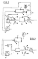
- FIG. 2 partially schematically illustrates another embodiment of the invention, more particularly intended for regulating the flow at the level of the filling spouts during the start and stop phases of the installation.
- the feed member 1 is this time a centrifugal pump disposed on a section of feed pipe 14 common to several filling spouts.
- the common feed pipe 14 is subdivided into individual feed pipes 15.
- the filling device comprises in the same way as previously a weighing member 5 associated with each filling spout 2, this weighing member being connected to a weight processing unit 4 comprising a time measuring member 11.
- the supply pressure exerted by the supply pump 1 in the individual pipes is higher when only one filling spout, or a small number of filling spouts, is in service only when all the filling spouts are in service.
- the filling spouts are adjusted for a dynamic supply pressure corresponding to the commissioning of all the filling spouts.
- the time measuring member 11 is used as before to measure an effective filling time and a common management unit 8 performs as before a comparison with a time setpoint and sends, if necessary, a signal to the control valve 16 in an opening or closing direction thereof.
- the time measuring member 11 In its application to the start-up of the machine, the time measuring member 11, in conjunction with the signals sent by the weighing member 5, is used to calculate an instantaneous flow rate of the filling spouts in service.
- the common management unit 8 then performs a comparison of the instantaneous flow rates recorded, or of the average of these instantaneous flow rates, with a set point value of instantaneous flow rates which acts on the regulating valve 16 as a function of this comparison.
- the valve 16 When the machine is started, the valve 16 is adjusted to a minimum opening ensuring sufficient flow for the operation of the first filling spout which will be put into service.
- the common management unit 8 is then used to gradually close the control valve 16 to ensure a constant flow to the level of each filling spout.
- the measurement of the instantaneous flow rate can be used to act on the regulating valve 16 not only during the start and stop phase of the machine, but also during the normal operation phase of the machine in order to ensure a regulation of the flow in the main pipe 14 during disturbances which may occur, for example variations in the viscosity of the product to be packaged.
- the instantaneous flow is used alone without calculating the effective filling time of the containers, it is no longer possible to switch to timed mode in the event of failure of a weighing member 5.
- the device according to the invention is therefore preferably produced by simultaneously providing an instantaneous flow calculation and an effective calculation time for filling the containers.
- FIG. 3 illustrates a third embodiment in which the filling device comprises, as in the case of FIG. 2, a centrifugal pump 1 supplying a common pipe 14. Immediately downstream of the centrifugal pump 1, the common pipe 14 is subdivided into individual pipes 15. On each of them is arranged a variable opening flow control member 17 for supplying a filling spout 2 which, in this embodiment, does not include a closing valve.
- the device furthermore comprises a weight processing unit 4 comprising a time measuring member 11 and connected at the input to the weighing member 5 and by self-checking 13, and at the output to the control member d flow 17 and alarm 12.
- This device operates either at a constant flow rate by measuring an effective filling time as in the case of the device in FIG. 1, or by using the time measurement member 11 to calculate an instantaneous flow rate and, if necessary, to vary the flow reference value based on parameters chosen in advance. For example, it has been found that it is often desirable to start filling a container at a very low flow rate to avoid foaming when the product hits the bottom of the container until a sufficient quantity of product has was introduced to form a mobile layer in the bottom of the container. A first flow reference value is therefore introduced into the memory of the weight processing unit 4 before the machine is started.
- the quantity of product to be introduced to form the mobile layer corresponds to a weight of product to be packaged which, when detected by the weighing member 5, triggers a change from the flow reference value to a second reference value higher than the first reference value, and also in memory, to allow rapid filling of the major part of the container until the mass of product introduced into the container reaches a second threshold, for example 10% below the mass of product to introduce.
- a second threshold for example 10% below the mass of product to introduce.
- the times of each filling phase can be memorized and serve for a timed filling in the event of failure of the weighing member detected by the self-checking means 13.
- the filling spout 2 is preferably at a sufficient distance from the flow control member 17 to allow stabilization of the flow in the pipe part downstream of the flow control member 17.
- the lower opening of the filling spout is preferably at a higher level than the flow control member 17.
- variable opening flow control member 17 with a regulating valve arranged on the common pipe 14 upstream of the division into individual supply pipes.
- the device according to the invention is particularly useful in the frequent case of a supply by a reservoir whose level varies in significant proportions during conditioning, thus varying the supply pressure in the same proportions.
- a regulating valve 16 or 17 In the case where a regulating valve 16 or 17 is used, and more particularly in the case where the supply member is a variable level tank, provision may be usefully made for adjusting the initial opening in the valve. regulation as a function of the static pressure measured upstream of this valve and sent to the weight processing unit 4 or to the management unit 8, or their equivalent in the machine concerned.
Landscapes
- Engineering & Computer Science (AREA)
- Mechanical Engineering (AREA)
- Physics & Mathematics (AREA)
- General Physics & Mathematics (AREA)
- Basic Packing Technique (AREA)
- Filling Of Jars Or Cans And Processes For Cleaning And Sealing Jars (AREA)
Claims (12)
- Vorrichtung zum Füllen von Behältern umfassend ein Zuführorgan (1), das mit mindestens einem Füllstutzen (2) über ein Ausflußsteuerorgan (3, 16, 17) verbunden ist, welches an einen Ausgang einer Einheit (4) zur Verarbeitung von Gewichtsinformation angeschlossen ist, die einen mit einem Wiegeorgan (5) verbundenen Eingang hat, um Öffnungs- oder Schließsignale an das Ausflußsteuerorgan in Abhängigkeit eines von dem Wiegeorgan gemessenen Gewichtes zu senden, und die ein mit der Einheit zur Verarbeitung von Gewichtsinformation verbundenes Zeitmeßglied (11) hat, um mittels derselben das Gewicht eines in einer vorgegebenen Zeit ausfließenden Produktes zu messen, dadurch gekennzeichnet, daß die Einheit zur Verarbeitung von Gewichtsinformation den momentanen Ausstoß des durch das Ausflußsteuerorgan fließenden Produktes berechnet, den berechneten momentanen Ausstoß mit einem Referenz - Ausstoß vergleicht und den Ausstoß des Produktes kontinuierlich in Abhängigkeit des Vergleichsergebnisses einstellt, um den Ausstoß gleich dem Referenzausstoß zu halten.
- Vorrichtung nach Anspruch 1, dadurch gekennzeichnet, daß das Ausflußsteuerorgan ein jedem Füllstutzen zugeordnetes Steuerelement (3) und ein Regelelement (16) umfaßt, welches mehreren Füllstutzen gemeinsam zugeordnet ist.
- Vorrichtung nach Anspruch 2, dadurch gekennzeichnet, daß das jedem Füllstutzen zugeordnete Steuerelement einen variablen Öffnungsquerschnitt hat, daß die jedem Füllstutzen zugeordnete Einheit (4) zur Verarbeitung von Gewichtsinformation einen individuellen Vergleich mit einem Referenzausstoßwert für jeden Füllstutzen ausführt und daß die Vorrichtung ein gemeinsames Steuerorgan (8) zur Aufsummierung der berechneten Ausstoßwerte mehrerer Füllstutzen und zur Beeinflussung des gemeinsamen Regelelementes (16) umfaßt.
- Vorrichtung nach Anspruch 1, dadurch gekennzeichnet, daß das jedem Füllstutzen zugeordnete Ausflußsteuerorgan (17) eine Öffnung variablen Querschnittes hat und daß der Ausstoß des Produktes für jeden Füllstutzen eingestellt wird, in dem man auf jedes zugeordnete Ausflußsteuerorgan einwirkt.
- Vorrichtung nach Anspruch 4, dadurch gekennzeichnet, daß das Ausflußsteuerorgan (17) von dem Füllstutzen durch einen Kanal ausreichender Länge getrennt ist, um eine Stabilisierung des Ausflusses vor dem Füllstzutzen (2) zu erreichen, und daß der Füllstutzen (2) eine untere Öffnung hat, die auf einem gegenüber dem Ausflußsteuerorgan (17) höheren Niveau angeordnet ist.
- Vorrichtung nach einem der Ansprüche 3, 4 oder 5 dadurch gekennzeichnet, daß der Referenzausstoßwert jedes Füllstutzens variabel ist in Abhängigkeit des Füllgrades des entsprechenden Behälters.
- Vorrichtung nach einem der Ansprüche 1 bis 5, dadurch gekennzeichnet, daß das Zeitmeßorgan (11) eine effektive Füllzeit mißt, während welcher das Ausflußsteuerorgan (3) geöffnet ist, und daß die Vorrichtung Mittel (8) zum Vergleichen der effektiven Füllzeit mit einer vorgegebenen Zeit sowie Mittel (9) umfaßt, um in Abhängigkeit einer Differenz zwischen der effektiven Füllzeit und der vorgegebenen Füllzeit Maßnahmen auszuführen, um den Ausstoß des Produktes durch das Ausflußsteuerorgan (3) im wesentlichen konstant zu halten.
- Vorrichtung nach Anspruch 7, dadurch gekennzeichnet, daß sie Mittel (8) zum Vergleichen der effektiven Füllzeit mit einer kritischen Füllzeit und Mittel zur Auslösung eines Alarmes (12) umfaßt, wenn die effektive Füllzeit die kritische Füllzeit erreicht.
- Vorrichtung nach Anspruch 7 oder 8, umfassend mehrere Füllstutzen (2), dadurch gekennzeichnet, daß sie ein gemeinsames Steuerorgan (8) hat, um einen Mittelwert der effektiven Füllzeiten für jeden Füllstutzen zu bilden und den Ausstoß durch die Ausflußsteuerorgane in Abhängigkeit einer Differenz zwischen dem Mittelwert der effektiven Füllzeiten und der vorgegebenen Zeit zu steuern.
- Vorrichtung nach einem der Ansprüche 7 bis 9, bei welcher das Zuführorgan eine Zuführwanne (1) mit Niveauregelung ist, dadurch gekennzeichnet, daß die Mittel zur Einhaltung eines im wesentlichen konstanten Produktausstoßes auf das Produktniveau in der Zuführwanne einwirken.
- Vorrichtung nach Anspruch 9 oder 10, bei welcher die Wiegeorgane (5) Selbstüberwachungsmittel (13) zum Erfassen eines fehlerhaften Wiegeorganes haben, dadurch gekennzeichnet, daß die Steuereinrichtung (8) mit den Selbstüberwachungsmittel (13) verbunden ist, um das einem fehlerhaften Wiegeorgan zugeordnete Ausflußsteuerorgan (3) entsprechend einer Zeitsteuerung unter Kurzschließen der entsprechenden Einheit (4) zur Verarbeitung von Gewichtsinformation zu steuern, wobei die Zeitsteuerung in Abhängigkeit des Mittelwertes der effektiven Füllzeiten an den anderen Füllstutzen erfolgt.
- Vorrichtung nach Anspruch 11, dadurch gekennzeichnet, daß das Steuerorgan (8) Mittel zur Speicherung der effektiven Füllzeiten an jedem Füllstutzen hat und daß die Zeitsteuerung für einen Füllstutzen in Abhängigkeit des Mittelwertes der effektiven Füllzeiten und mindestens einer effektiven Füllzeit an diesem Füllstutzen vor dem Übergang zur Zeitsteuerung erfolgt.
Applications Claiming Priority (4)
| Application Number | Priority Date | Filing Date | Title |
|---|---|---|---|
| FR8908529 | 1989-06-27 | ||
| FR9000852 | 1990-01-25 | ||
| FR9000852A FR2657325B1 (fr) | 1990-01-25 | 1990-01-25 | Dispositif de remplissage de recipients a dosage ponderal. |
| FR8908529 | 1990-01-25 |
Publications (2)
| Publication Number | Publication Date |
|---|---|
| EP0406092A1 EP0406092A1 (de) | 1991-01-02 |
| EP0406092B1 true EP0406092B1 (de) | 1993-01-13 |
Family
ID=26227430
Family Applications (1)
| Application Number | Title | Priority Date | Filing Date |
|---|---|---|---|
| EP90401807A Expired - Lifetime EP0406092B1 (de) | 1989-06-27 | 1990-06-25 | Vorrichtung zum Füllen von Behältern mit abgewogenen Mengen |
Country Status (6)
| Country | Link |
|---|---|
| US (1) | US5148841A (de) |
| EP (1) | EP0406092B1 (de) |
| JP (1) | JP2598834B2 (de) |
| BR (1) | BR9003143A (de) |
| DE (1) | DE69000764T2 (de) |
| ES (1) | ES2037532T3 (de) |
Families Citing this family (70)
| Publication number | Priority date | Publication date | Assignee | Title |
|---|---|---|---|---|
| FR2669616B1 (fr) * | 1990-11-23 | 1993-01-08 | Atochem | Procede de remplissage de futs par des liquides non miscibles et ses applications, notamment a l'enfutage du phosphore blanc. |
| DE4112091A1 (de) * | 1991-04-12 | 1992-10-15 | Heller Guenther | Verfahren zur kontrolle einer fluessigkeitsmenge und vorrichtung |
| FR2679516B1 (fr) * | 1991-07-23 | 1993-11-12 | Andre Graffin | Procede et dispositif de dosage ponderal pour remplissage de recipients. |
| FR2686415B1 (fr) * | 1992-01-20 | 1994-04-01 | Simon Freres | Dispositif de dosage ponderal de produit pateux et/ou visqueux ainsi que procede mis en óoeuvre par l'utilisation de ce dispositif. |
| SE9201037L (sv) * | 1992-04-02 | 1993-05-17 | Ivan Haakansson | Saett och apparat foer att fylla vaetskedoser i behaallare |
| FR2693549B1 (fr) * | 1992-07-07 | 1996-12-13 | Pack Realisations | Procede de correction de dosage et installation utilisant ce procede. |
| US5402834A (en) * | 1992-11-25 | 1995-04-04 | Merck & Co., Inc. | Solution preparation system |
| US5597094A (en) * | 1992-12-03 | 1997-01-28 | Solignac Industries S.A. | Device with peristaltic pump which makes it possible to draw, weight and mix liquids automatically |
| ES2124804T3 (es) * | 1993-03-14 | 1999-02-16 | Hedrich Vakuumanlagen Wilhelm | Procedimiento y dispositivo para llenar moldes de colada con resina de colada o fluidos colables similares. |
| IT1272103B (it) * | 1993-03-17 | 1997-06-11 | I A S Ind Automation Systems A | Apparecchiatura per l'erogazione di una sostanza fluida,in quantita' dosate |
| US5375634A (en) * | 1993-10-07 | 1994-12-27 | Graco Inc. | Variable mass flow rate fluid dispensing control |
| FR2711610B1 (fr) * | 1993-10-29 | 1996-02-02 | Andre J J Graffin | Procédé de remplissage d'un récipient avec un poids net de référence. |
| US5505233B1 (en) * | 1993-11-08 | 1999-05-11 | Newpak Inc | Mobile and flushable container filling unit |
| US5460209A (en) * | 1993-12-08 | 1995-10-24 | Massachusetts Institute Of Technology | Automatic dispenser for dry ingredients |
| DE4341934A1 (de) * | 1993-12-09 | 1995-06-14 | Bosch Gmbh Robert | Verfahren und Vorrichtung zum Dosieren und Abfüllen einer Flüssigkeit in Verpackungsbehälter |
| US5499656A (en) * | 1993-12-23 | 1996-03-19 | Hughes Aircraft Company | Integrated storage and transfer system and method for spacecraft propulsion systems |
| US5464047A (en) * | 1994-01-24 | 1995-11-07 | Benjamin Moore & Co. | Method and apparatus for dispensing paint into containers |
| EP0688649B1 (de) * | 1994-05-20 | 2001-07-11 | Vlt Corporation | Formenabfüllverfahren |
| US5490547A (en) * | 1994-08-12 | 1996-02-13 | Abadi; Meyer | System for providing a supply of chilled fluid |
| EP0700830A1 (de) * | 1994-09-12 | 1996-03-13 | Holger Ermes | Verfahren zum eichgenauen Abfüllen von hochviskosen Flüssigkeiten |
| US5615717A (en) * | 1994-12-22 | 1997-04-01 | Dreisbach Electromotive Inc. | Electrolyte distributing system and method |
| JP2633820B2 (ja) * | 1995-06-16 | 1997-07-23 | ボッシュ包装機株式会社 | 液体の圧力充填方法 |
| GB2307230A (en) * | 1995-11-20 | 1997-05-21 | Mfw Systems Ltd | Filling a pressurised container |
| WO1997021590A1 (en) * | 1995-12-12 | 1997-06-19 | Kao Corporation | Method and apparatus for filling bulk material |
| US6170540B1 (en) * | 1998-04-14 | 2001-01-09 | Stephen Gilbert Romero | High speed depositor with positive displacement pump and stepping motor |
| US6213174B1 (en) * | 1998-04-17 | 2001-04-10 | Blue Boy International Limited | Portioning of flowable products |
| FR2785598B1 (fr) * | 1998-11-09 | 2000-12-01 | Sidel Sa | Procede pour remplir avec precision un recipient avec un liquide et dispositif pour la mise en oeuvre |
| US6148877A (en) * | 1999-04-22 | 2000-11-21 | Bethke; Steven D. | Fluid filling system with fill time optimization |
| FR2797258B1 (fr) * | 1999-07-19 | 2001-10-05 | Andre Graffin | Procede de remplissage d'un recipient |
| DE19951555A1 (de) * | 1999-10-27 | 2001-05-03 | Bausch & Stroebel Maschf | Einrichtung zum dosierten Abfüllen einer Flüssigkeit in Behälter |
| US6541063B1 (en) | 1999-11-04 | 2003-04-01 | Speedline Technologies, Inc. | Calibration of a dispensing system |
| US6472615B1 (en) * | 2000-09-08 | 2002-10-29 | Gustafson, Llc | Bulk flow measurement system |
| ITBO20010108A1 (it) * | 2001-02-28 | 2002-08-28 | Azionaria Costruzioni Automati | Macchina per il riempimento di contenitori |
| ITBO20010109A1 (it) * | 2001-02-28 | 2002-08-28 | Azionaria Costruzioni Automati | Macchina per il riempimento di contenitori |
| ITBO20010161A1 (it) * | 2001-03-21 | 2002-09-21 | Azionaria Costruzioni Automati | Apparecchiatura per riempire contenitori con materiali, preferibilmente liquidi |
| US6985341B2 (en) * | 2001-04-24 | 2006-01-10 | Vlt, Inc. | Components having actively controlled circuit elements |
| US7443229B1 (en) | 2001-04-24 | 2008-10-28 | Picor Corporation | Active filtering |
| US6644344B2 (en) * | 2001-05-11 | 2003-11-11 | Ashland, Inc. | Method and apparatus for metering a flow rate of a fluid |
| DE10209435C1 (de) * | 2002-03-05 | 2003-08-14 | Feige Abfuelltechnik | Vorrichtung zum gleichzeitigen Befüllen mehrerer Behälter |
| US6811301B2 (en) | 2002-03-29 | 2004-11-02 | Hydreclaim, Inc. | Feeder control system for an automated blender system |
| JP4207543B2 (ja) * | 2002-11-21 | 2009-01-14 | 澁谷工業株式会社 | 回転式重量充填装置 |
| US20040148763A1 (en) * | 2002-12-11 | 2004-08-05 | Peacock David S. | Dispensing system and method |
| ES2526909T5 (es) | 2004-06-23 | 2020-06-19 | Ecolab Inc | Método para la dosificación múltiple de productos líquidos, aparato de dosificación y sistema de dosificación |
| DE102004055751A1 (de) * | 2004-11-18 | 2006-05-24 | Sig Technology Ag | Verfahren und Vorrichtung zur Steuerung des Füllvorganges beim Abfüllen flüssiger bzw. pastöser Produkte in einzelne Behälter |
| JP4578216B2 (ja) * | 2004-12-01 | 2010-11-10 | 大和製衡株式会社 | 重量充填装置の制御方法及び重量充填装置 |
| US20060255061A1 (en) * | 2005-05-16 | 2006-11-16 | Case Medical Inc. | Concentrated cleaner/disinfection system for biomatter contaminated materials |
| ES2332292T3 (es) * | 2005-11-21 | 2010-02-01 | Mannkind Corporation | Aparato y procedimientos de dispensacion y deteccion de polvo. |
| DE102006029490C5 (de) * | 2006-06-27 | 2015-07-02 | Khs Gmbh | Verfahren zur Steuerung einer Füllanlage |
| AU2007302610B2 (en) * | 2006-09-26 | 2014-04-10 | Autopour Pty Ltd | Dispensing apparatus and weighing process with control unit |
| DE102008016846A1 (de) * | 2008-04-01 | 2009-10-15 | Khs Ag | Verfahren und Vorrichtung zum Füllen von insbesondere großvolumigen Behältern |
| DE102008018089A1 (de) * | 2008-04-09 | 2009-10-15 | Endress & Hauser Meßtechnik GmbH & Co. KG | Verfahren zum Abfüllen eines Mediums |
| EP2372321B1 (de) * | 2010-02-24 | 2012-11-07 | Mettler-Toledo AG | Verfahren und Vorrichtung zum Füllen von Zielbehältern |
| US8534497B2 (en) | 2010-09-20 | 2013-09-17 | Prince Castle, LLC | Dispensing method and apparatus utilizing a sensor to determine a time that a dispensing valve is open |
| DE102010053201A1 (de) * | 2010-12-03 | 2012-06-06 | Krones Aktiengesellschaft | Vorrichtung und Verfahren zum Befüllen von Behältnissen |
| JP5751866B2 (ja) * | 2011-03-03 | 2015-07-22 | 三菱重工業株式会社 | 容器内充填物検査装置、及び充填物充填装置 |
| US20130248538A1 (en) | 2012-03-23 | 2013-09-26 | Prince Castle, LLC | Holding Tank With Internally Reinforced Sidewalls and Liquid Dispenser Using Same |
| DE102012102965A1 (de) * | 2012-04-04 | 2013-10-10 | Krones Ag | Verfahren zur Steuerung eines Füllers |
| DE102013106756A1 (de) * | 2013-06-27 | 2014-12-31 | Khs Gmbh | Verfahren sowie Füllsystem zum Füllen von Behältern |
| ES2447315B1 (es) * | 2013-07-30 | 2014-09-10 | Grifols Worldwide Operations Limited | Máquina y procedimiento para el llenado de contenedores de productos farmacéuticos |
| CN104369887A (zh) * | 2014-08-27 | 2015-02-25 | 梧州市旺捷机械制造有限公司 | 液体灌装机 |
| US10494200B2 (en) | 2016-04-25 | 2019-12-03 | Chevron Phillips Chemical Company Lp | Measurement of product pellets flow rate |
| DE102017207307A1 (de) | 2017-03-13 | 2018-09-13 | Bausch + Ströbel Maschinenfabrik Ilshofen GmbH + Co. KG | System mit alternierender Füllung von Behältern und Verfahren hierzu |
| EP3625133B1 (de) * | 2017-05-19 | 2021-10-06 | Cryovac, Inc. | Verpackung feedback-regelungssystem und zugehörige verfahren |
| JP7011882B2 (ja) * | 2018-01-24 | 2022-01-27 | 株式会社エー・アンド・デイ | 流量計機能を有する計量装置 |
| EP3527960B1 (de) * | 2018-02-14 | 2022-01-19 | MG Colors GmbH | Verfahren zur lackabfüllung |
| EP3765400B1 (de) * | 2018-03-12 | 2026-01-07 | Ebar Initiatives Ltd | Getränkespender mit gegendruck und verwendungsmethode |
| US10850964B2 (en) * | 2019-03-22 | 2020-12-01 | Accenture Global Solutions Limited | System and method for filling containers with a precise amount of fluid |
| CN111792604A (zh) * | 2020-07-22 | 2020-10-20 | 姜跃辉 | 一种可调灌装容量大小的化妆品灌装装置 |
| CN116568602A (zh) | 2020-12-17 | 2023-08-08 | 利乐拉瓦尔集团及财务有限公司 | 基于强化学习增强食物包装系统中包装的形成 |
| CN116101958B (zh) * | 2023-03-22 | 2024-07-23 | 德玛克(嘉兴)智能装备有限公司 | 大桶饮用水智能化灌装方法及其系统 |
Family Cites Families (25)
| Publication number | Priority date | Publication date | Assignee | Title |
|---|---|---|---|---|
| US1153307A (en) * | 1914-06-05 | 1915-09-14 | Charlie J Hunter | Portable soda-fountain. |
| US2901209A (en) * | 1956-01-30 | 1959-08-25 | Armour Res Found | Container filling machine |
| US2925835A (en) * | 1958-03-31 | 1960-02-23 | Kartridg Pak Machine Co | Automatic filling and weight checking machine |
| US3484813A (en) * | 1967-11-07 | 1969-12-16 | Nat Biscuit Co | Container filling apparatus with automatic checkweigher |
| US3786844A (en) * | 1971-08-12 | 1974-01-22 | Procter & Gamble | Filling containers with friable particles |
| AT366179B (de) * | 1974-04-08 | 1982-03-25 | Ife Gmbh | Anordnung fuer die chargenverwiegung von fluessigkeiten und schuettguetern |
| US3985266A (en) * | 1975-08-13 | 1976-10-12 | K-Tron Corporation | Apparatus for controlling the feed rate and batch size of a material feeder |
| SE442350B (sv) * | 1977-10-17 | 1985-12-16 | Alfa Laval Ab | Process-styrningssystem |
| JPS6055398B2 (ja) * | 1977-11-24 | 1985-12-04 | 花王株式会社 | 充填機の速度制御方法 |
| US4211263A (en) * | 1978-10-16 | 1980-07-08 | Velasco Scale Company | Dual fill rate liquid filler apparatus having a single control valve |
| WO1980001797A1 (en) * | 1979-02-22 | 1980-09-04 | D Haig | Precision material filling systems |
| GB2077434B (en) * | 1980-05-30 | 1984-04-26 | Millar John | Ascertaining flow rate through valves or pumps |
| FR2493800A1 (fr) * | 1980-11-13 | 1982-05-14 | Serac Sa | Procede et dispositif de controle de materiaux de remplissage dans une machine de remplissage a dosage ponderal |
| JPS5864996A (ja) * | 1981-10-13 | 1983-04-18 | 株式会社東京タツノ | 自動給液装置 |
| US4467844A (en) * | 1982-06-24 | 1984-08-28 | Baxter Travenol Laboratories, Inc. | Flow monitoring method and apparatus |
| US4513796A (en) * | 1982-06-24 | 1985-04-30 | Baxter Travenol Laboratories, Inc. | High speed bulk compounder |
| JPS5952719A (ja) * | 1982-09-20 | 1984-03-27 | Ishida Scales Mfg Co Ltd | 組み合せ計量方式 |
| US4630654A (en) * | 1984-08-10 | 1986-12-23 | Patrick Howard Gibson | Apparatus for liquid filling of containers |
| IT1176915B (it) * | 1984-10-10 | 1987-08-18 | Logic Srl | Impianto di controllo e procedimento per il riempimento ponderale di bottiglie, flaconi e simili |
| DE3523502A1 (de) * | 1985-07-01 | 1987-01-08 | Peters Ag Claudius | Verfahren zum auswaegen einer vorbestimmten schuettgutmenge im kontinuierlichen abfuellstrom |
| CH667530A5 (de) * | 1985-10-15 | 1988-10-14 | Chematec Ag | Verfahren zum betreiben von dosiervorrichtungen. |
| US4696329A (en) * | 1986-06-09 | 1987-09-29 | Mateer Burt Co., Inc. | Feedback control for automatic filling machine |
| JPS6367295A (ja) * | 1986-09-08 | 1988-03-26 | 三菱重工業株式会社 | 液体充填方法及び装置 |
| ATE65128T1 (de) * | 1987-05-21 | 1991-07-15 | Schenck Ag Carl | Verfahren zur regelung einer differentialdosierwaage, insbesondere fuer schuettgueter, und differential-dosierwaage zur durchfuehrung des verfahrens. |
| JPS63294392A (ja) * | 1987-05-21 | 1988-12-01 | 藤沢薬品工業株式会社 | 液体の定量充填装置 |
-
1990
- 1990-06-25 DE DE9090401807T patent/DE69000764T2/de not_active Expired - Fee Related
- 1990-06-25 US US07/542,696 patent/US5148841A/en not_active Expired - Lifetime
- 1990-06-25 ES ES199090401807T patent/ES2037532T3/es not_active Expired - Lifetime
- 1990-06-25 EP EP90401807A patent/EP0406092B1/de not_active Expired - Lifetime
- 1990-06-27 BR BR909003143A patent/BR9003143A/pt not_active IP Right Cessation
- 1990-06-27 JP JP2166971A patent/JP2598834B2/ja not_active Expired - Fee Related
Also Published As
| Publication number | Publication date |
|---|---|
| BR9003143A (pt) | 1990-12-18 |
| DE69000764T2 (de) | 1993-05-13 |
| DE69000764D1 (de) | 1993-02-25 |
| ES2037532T3 (es) | 1993-06-16 |
| JPH0369495A (ja) | 1991-03-25 |
| US5148841A (en) | 1992-09-22 |
| EP0406092A1 (de) | 1991-01-02 |
| JP2598834B2 (ja) | 1997-04-09 |
Similar Documents
| Publication | Publication Date | Title |
|---|---|---|
| EP0406092A1 (de) | Vorrichtung zum Füllen von Behältern mit abgewogenen Mengen | |
| EP0524850B1 (de) | Verfahren zur gewichtsmässigen Dosierung beim Füllen von Behältern | |
| EP0724528B2 (de) | Verfahren zur füllung eines behälters mit einem referenznettogewicht | |
| FR2519162A1 (fr) | Procede et dispositif d'etalonnage pour un appareil de pulverisation de fluide avec regulation de debit | |
| EP1913851A2 (de) | Vorrichtung zum Erhitzen einer Flüssigkeit und Verfahren zum Erhitzen einer Flüssigkeit | |
| EP0557667B1 (de) | Ausgabeverfahren von portionierten Flüssigkeitsmengen, insbesondere von viskosen Flüssigkeiten, und Vorrichtung zur Durchführung des Verfahrens | |
| EP0473521B1 (de) | Verfahren und Vorrichtung zum Fördern von pulverförmigem oder körnigem Material in eine Stranggussform | |
| FR2797258A1 (fr) | Procede de remplissage d'un recipient | |
| US6695017B1 (en) | Method and apparatus for filling a pressure tank with a fluid | |
| FR2532369A1 (fr) | Dispositif et procede de commande d'un systeme a fluide | |
| WO2010112686A1 (fr) | Dispositif de distribution dosée de produits liquides ou visqueux et procédé de mise en oeuvre de ce dispositif | |
| EP0204935B1 (de) | Verfahren zum Kontrollieren der Beschickung eines Schachtofens | |
| FR2513553A1 (fr) | Dispositif de pompage et de mesure | |
| FR2661233A1 (fr) | Generateur de vapeur. | |
| EP0656316B1 (de) | Hochleistungsabgabevorrichtung für Flüssigkeiten | |
| FR2657325A1 (fr) | Dispositif de remplissage de recipients a dosage ponderal. | |
| FR2520864A1 (fr) | Debitmetre et installation de melange d'un additif dans un liquide comprenant un tel debitmetre | |
| EP0403401B1 (de) | Verfahren zur Kontrolle der Ultrafiltration und Vorrichtung zur Ausführung des Verfahrens | |
| EP0401139B1 (de) | Gerät und Verfahren für die Ultrafilterungsmessung in einer Kunstniere | |
| FR2555132A1 (fr) | Procede de remplissage d'un recipient d'une quantite determinee de produit | |
| FR2924706A1 (fr) | Installation de distribution de carburant renfermant un dispsositif de recuperation de vapeurs ainsi que procede mis en oeuvre lors de l'utilisation de cette installation. | |
| WO2023117307A1 (fr) | Installation et procédé de conditionnement d'un mélange de gaz | |
| EP0120778A1 (de) | Verfahren und Vorrichtung zum Füllen eines Behälters | |
| FR2655885A1 (fr) | Dispositif de controle de pression dans un systeme de depose de produit epais ou pateux sous pression. | |
| WO2022073612A1 (fr) | Dispositif de dosage pour une machine de fabrication de preparation liquide |
Legal Events
| Date | Code | Title | Description |
|---|---|---|---|
| PUAI | Public reference made under article 153(3) epc to a published international application that has entered the european phase |
Free format text: ORIGINAL CODE: 0009012 |
|
| 17P | Request for examination filed |
Effective date: 19900627 |
|
| AK | Designated contracting states |
Kind code of ref document: A1 Designated state(s): BE CH DE ES FR GB IT LI NL |
|
| 17Q | First examination report despatched |
Effective date: 19910531 |
|
| RAP1 | Party data changed (applicant data changed or rights of an application transferred) |
Owner name: S.E.R.A.C. GROUP |
|
| GRAA | (expected) grant |
Free format text: ORIGINAL CODE: 0009210 |
|
| AK | Designated contracting states |
Kind code of ref document: B1 Designated state(s): BE CH DE ES FR GB IT LI NL |
|
| ITF | It: translation for a ep patent filed | ||
| GBT | Gb: translation of ep patent filed (gb section 77(6)(a)/1977) |
Effective date: 19930127 |
|
| REF | Corresponds to: |
Ref document number: 69000764 Country of ref document: DE Date of ref document: 19930225 |
|
| REG | Reference to a national code |
Ref country code: ES Ref legal event code: FG2A Ref document number: 2037532 Country of ref document: ES Kind code of ref document: T3 |
|
| PLBE | No opposition filed within time limit |
Free format text: ORIGINAL CODE: 0009261 |
|
| STAA | Information on the status of an ep patent application or granted ep patent |
Free format text: STATUS: NO OPPOSITION FILED WITHIN TIME LIMIT |
|
| 26N | No opposition filed | ||
| REG | Reference to a national code |
Ref country code: FR Ref legal event code: GC |
|
| REG | Reference to a national code |
Ref country code: GB Ref legal event code: IF02 |
|
| PGFP | Annual fee paid to national office [announced via postgrant information from national office to epo] |
Ref country code: ES Payment date: 20060626 Year of fee payment: 17 |
|
| PGFP | Annual fee paid to national office [announced via postgrant information from national office to epo] |
Ref country code: NL Payment date: 20060627 Year of fee payment: 17 |
|
| PGFP | Annual fee paid to national office [announced via postgrant information from national office to epo] |
Ref country code: FR Payment date: 20060628 Year of fee payment: 17 |
|
| PGFP | Annual fee paid to national office [announced via postgrant information from national office to epo] |
Ref country code: GB Payment date: 20060629 Year of fee payment: 17 |
|
| PGFP | Annual fee paid to national office [announced via postgrant information from national office to epo] |
Ref country code: CH Payment date: 20060630 Year of fee payment: 17 Ref country code: IT Payment date: 20060630 Year of fee payment: 17 |
|
| PGFP | Annual fee paid to national office [announced via postgrant information from national office to epo] |
Ref country code: BE Payment date: 20060711 Year of fee payment: 17 |
|
| PGFP | Annual fee paid to national office [announced via postgrant information from national office to epo] |
Ref country code: DE Payment date: 20060731 Year of fee payment: 17 |
|
| BERE | Be: lapsed |
Owner name: *S.E.R.A.C. GROUP Effective date: 20070630 |
|
| REG | Reference to a national code |
Ref country code: CH Ref legal event code: PL |
|
| GBPC | Gb: european patent ceased through non-payment of renewal fee |
Effective date: 20070625 |
|
| NLV4 | Nl: lapsed or anulled due to non-payment of the annual fee |
Effective date: 20080101 |
|
| PG25 | Lapsed in a contracting state [announced via postgrant information from national office to epo] |
Ref country code: BE Free format text: LAPSE BECAUSE OF NON-PAYMENT OF DUE FEES Effective date: 20070630 |
|
| REG | Reference to a national code |
Ref country code: FR Ref legal event code: ST Effective date: 20080229 |
|
| PG25 | Lapsed in a contracting state [announced via postgrant information from national office to epo] |
Ref country code: CH Free format text: LAPSE BECAUSE OF NON-PAYMENT OF DUE FEES Effective date: 20070630 Ref country code: DE Free format text: LAPSE BECAUSE OF NON-PAYMENT OF DUE FEES Effective date: 20080101 Ref country code: NL Free format text: LAPSE BECAUSE OF NON-PAYMENT OF DUE FEES Effective date: 20080101 Ref country code: LI Free format text: LAPSE BECAUSE OF NON-PAYMENT OF DUE FEES Effective date: 20070630 |
|
| PG25 | Lapsed in a contracting state [announced via postgrant information from national office to epo] |
Ref country code: GB Free format text: LAPSE BECAUSE OF NON-PAYMENT OF DUE FEES Effective date: 20070625 |
|
| REG | Reference to a national code |
Ref country code: ES Ref legal event code: FD2A Effective date: 20070626 |
|
| PG25 | Lapsed in a contracting state [announced via postgrant information from national office to epo] |
Ref country code: FR Free format text: LAPSE BECAUSE OF NON-PAYMENT OF DUE FEES Effective date: 20070702 |
|
| PG25 | Lapsed in a contracting state [announced via postgrant information from national office to epo] |
Ref country code: ES Free format text: LAPSE BECAUSE OF NON-PAYMENT OF DUE FEES Effective date: 20070626 |
|
| PG25 | Lapsed in a contracting state [announced via postgrant information from national office to epo] |
Ref country code: IT Free format text: LAPSE BECAUSE OF NON-PAYMENT OF DUE FEES Effective date: 20070625 |