EP0406431A1 - Structure de retenue de palier pour moteurs electriques - Google Patents
Structure de retenue de palier pour moteurs electriques Download PDFInfo
- Publication number
- EP0406431A1 EP0406431A1 EP89911104A EP89911104A EP0406431A1 EP 0406431 A1 EP0406431 A1 EP 0406431A1 EP 89911104 A EP89911104 A EP 89911104A EP 89911104 A EP89911104 A EP 89911104A EP 0406431 A1 EP0406431 A1 EP 0406431A1
- Authority
- EP
- European Patent Office
- Prior art keywords
- bearing
- housing
- layer
- hold
- electrical motor
- Prior art date
- Legal status (The legal status is an assumption and is not a legal conclusion. Google has not performed a legal analysis and makes no representation as to the accuracy of the status listed.)
- Withdrawn
Links
- XEEYBQQBJWHFJM-UHFFFAOYSA-N Iron Chemical compound [Fe] XEEYBQQBJWHFJM-UHFFFAOYSA-N 0.000 claims abstract description 24
- 239000000463 material Substances 0.000 claims abstract description 15
- 229910052742 iron Inorganic materials 0.000 claims abstract description 12
- OKTJSMMVPCPJKN-UHFFFAOYSA-N Carbon Chemical compound [C] OKTJSMMVPCPJKN-UHFFFAOYSA-N 0.000 claims description 5
- 229910001018 Cast iron Inorganic materials 0.000 claims description 5
- 229910002804 graphite Inorganic materials 0.000 claims description 5
- 239000010439 graphite Substances 0.000 claims description 5
- 238000004512 die casting Methods 0.000 claims description 2
- 238000005520 cutting process Methods 0.000 abstract description 4
- 238000005266 casting Methods 0.000 description 10
- 238000003754 machining Methods 0.000 description 7
- XAGFODPZIPBFFR-UHFFFAOYSA-N aluminium Chemical compound [Al] XAGFODPZIPBFFR-UHFFFAOYSA-N 0.000 description 6
- 229910052782 aluminium Inorganic materials 0.000 description 6
- 238000003780 insertion Methods 0.000 description 2
- 230000037431 insertion Effects 0.000 description 2
- 230000002411 adverse Effects 0.000 description 1
- 230000015556 catabolic process Effects 0.000 description 1
- 238000010276 construction Methods 0.000 description 1
- 230000000694 effects Effects 0.000 description 1
- 238000010348 incorporation Methods 0.000 description 1
- 238000009413 insulation Methods 0.000 description 1
- 238000000034 method Methods 0.000 description 1
- 230000000717 retained effect Effects 0.000 description 1
- 238000004804 winding Methods 0.000 description 1
Images

Classifications
-
- F—MECHANICAL ENGINEERING; LIGHTING; HEATING; WEAPONS; BLASTING
- F16—ENGINEERING ELEMENTS AND UNITS; GENERAL MEASURES FOR PRODUCING AND MAINTAINING EFFECTIVE FUNCTIONING OF MACHINES OR INSTALLATIONS; THERMAL INSULATION IN GENERAL
- F16C—SHAFTS; FLEXIBLE SHAFTS; ELEMENTS OR CRANKSHAFT MECHANISMS; ROTARY BODIES OTHER THAN GEARING ELEMENTS; BEARINGS
- F16C35/00—Rigid support of bearing units; Housings, e.g. caps, covers
- F16C35/04—Rigid support of bearing units; Housings, e.g. caps, covers in the case of ball or roller bearings
- F16C35/06—Mounting or dismounting of ball or roller bearings; Fixing them onto shaft or in housing
- F16C35/07—Fixing them on the shaft or housing with interposition of an element
-
- F—MECHANICAL ENGINEERING; LIGHTING; HEATING; WEAPONS; BLASTING
- F16—ENGINEERING ELEMENTS AND UNITS; GENERAL MEASURES FOR PRODUCING AND MAINTAINING EFFECTIVE FUNCTIONING OF MACHINES OR INSTALLATIONS; THERMAL INSULATION IN GENERAL
- F16C—SHAFTS; FLEXIBLE SHAFTS; ELEMENTS OR CRANKSHAFT MECHANISMS; ROTARY BODIES OTHER THAN GEARING ELEMENTS; BEARINGS
- F16C25/00—Bearings for exclusively rotary movement adjustable for wear or play
- F16C25/06—Ball or roller bearings
- F16C25/08—Ball or roller bearings self-adjusting
-
- F—MECHANICAL ENGINEERING; LIGHTING; HEATING; WEAPONS; BLASTING
- F16—ENGINEERING ELEMENTS AND UNITS; GENERAL MEASURES FOR PRODUCING AND MAINTAINING EFFECTIVE FUNCTIONING OF MACHINES OR INSTALLATIONS; THERMAL INSULATION IN GENERAL
- F16C—SHAFTS; FLEXIBLE SHAFTS; ELEMENTS OR CRANKSHAFT MECHANISMS; ROTARY BODIES OTHER THAN GEARING ELEMENTS; BEARINGS
- F16C35/00—Rigid support of bearing units; Housings, e.g. caps, covers
- F16C35/04—Rigid support of bearing units; Housings, e.g. caps, covers in the case of ball or roller bearings
- F16C35/06—Mounting or dismounting of ball or roller bearings; Fixing them onto shaft or in housing
- F16C35/07—Fixing them on the shaft or housing with interposition of an element
- F16C35/077—Fixing them on the shaft or housing with interposition of an element between housing and outer race ring
-
- H—ELECTRICITY
- H02—GENERATION; CONVERSION OR DISTRIBUTION OF ELECTRIC POWER
- H02K—DYNAMO-ELECTRIC MACHINES
- H02K5/00—Casings; Enclosures; Supports
- H02K5/04—Casings or enclosures characterised by the shape, form or construction thereof
- H02K5/16—Means for supporting bearings, e.g. insulating supports or means for fitting bearings in the bearing-shields
- H02K5/173—Means for supporting bearings, e.g. insulating supports or means for fitting bearings in the bearing-shields using bearings with rolling contact, e.g. ball bearings
- H02K5/1732—Means for supporting bearings, e.g. insulating supports or means for fitting bearings in the bearing-shields using bearings with rolling contact, e.g. ball bearings radially supporting the rotary shaft at both ends of the rotor
-
- F—MECHANICAL ENGINEERING; LIGHTING; HEATING; WEAPONS; BLASTING
- F16—ENGINEERING ELEMENTS AND UNITS; GENERAL MEASURES FOR PRODUCING AND MAINTAINING EFFECTIVE FUNCTIONING OF MACHINES OR INSTALLATIONS; THERMAL INSULATION IN GENERAL
- F16C—SHAFTS; FLEXIBLE SHAFTS; ELEMENTS OR CRANKSHAFT MECHANISMS; ROTARY BODIES OTHER THAN GEARING ELEMENTS; BEARINGS
- F16C2226/00—Joining parts; Fastening; Assembling or mounting parts
- F16C2226/50—Positive connections
- F16C2226/70—Positive connections with complementary interlocking parts
- F16C2226/74—Positive connections with complementary interlocking parts with snap-fit, e.g. by clips
-
- F—MECHANICAL ENGINEERING; LIGHTING; HEATING; WEAPONS; BLASTING
- F16—ENGINEERING ELEMENTS AND UNITS; GENERAL MEASURES FOR PRODUCING AND MAINTAINING EFFECTIVE FUNCTIONING OF MACHINES OR INSTALLATIONS; THERMAL INSULATION IN GENERAL
- F16C—SHAFTS; FLEXIBLE SHAFTS; ELEMENTS OR CRANKSHAFT MECHANISMS; ROTARY BODIES OTHER THAN GEARING ELEMENTS; BEARINGS
- F16C2380/00—Electrical apparatus
- F16C2380/26—Dynamo-electric machines or combinations therewith, e.g. electro-motors and generators
Definitions
- the present invention relates to a hold structure for a bearing in a general-purpose electrical motor having a small size and a large output power, and able to rotate at a high speed.
- an output shaft of an electrical motor is journaled by bearings housed in a housing of the motor at the front and the rear thereof, and when the motor is applied as a drive source to an industrial machine such as a machine tool, a radial load and a thrust load are imposed on the output shaft thereof.
- the housing is formed by aluminum castings, and the front and the rear inner surfaces of this housing are often damaged due to a direct pressure exerted thereon by the bearings. Therefore, a layer containing iron as a main component thereof, which is hard and thus is not easily damaged, is provided at the inner portion of the housing receiving such a pressure, to enable a hold structure for a bearing to withstand a radial load.
- a member such as a C-shape ring when the bearings are incorporated in the housing, to retain the bearing so that it cannot move in the longitudinal direction of the motor.
- a groove is provided in the layer so that the member is retained in the inner portion of the housing, i.e., in the layer.
- the groove receives a thrust load acting on the output shaft through the bearings and the member, and therefore, is made of a ductile material containing iron as a main component thereof, such as FCD (Nodular Graphite Cast Iron) according to the JIS (Japanese Industrial Standard), to prevent damage.
- FCD Nodular Graphite Cast Iron
- an object of the present invention is to solve these problems by providing a hold structure for a bearing which prevents the generation of a burr when the portion for holding a bearing is machined.
- the present invention provides a hold structure for a bearing in an electrical motor having a front bearing and a rear bearing journaled on an output shaft, characterized in that an inner portion of a housing for holding an outer ring of one of the front and rear bearings is covered with a layer of a material containing iron as a main component thereof, a longitudinal inside end face of the layer is in tight contact with an end-hold member integrated with the housing, and each inner surface of the layer and the end-hold member is formed with the same diameter.
- the housing of an electrical motor is, in general, made of a free-cutting material such as an aluminum casting, and therefore, by adopting a structure wherein the longitudinal inside end face of the layer is in tight contact with the end-hold member constructed as a part of the housing, a burr is not generated at a point of the end face of the layer when the end-hold member as well as the layer is machined.
- a front housing 10 and a rear outer housing 14 constituting an outer periphery of a rear housing 13 are fixed to a central housing 12 consisting of a core portion of a stator 16, at the front or the rear thereof, and a rear inner housing 34 is attached to the inner side of the rear outer housing 14.
- a thin cylindrical and ductile nodular graphite cast iron member 24 of FCD according to the JIS is integrated with the front housing 10 at the inner surface thereof.
- the casting member 24 is inserted as an insert member when the front housing 10 is formed by aluminum die casting, to be integrated therewith.
- An output shaft 18 is journaled by bearings 26 and 36 held by the front and the rear housings 10 and 13 in the casing constructed as mentioned above, and a rotor 20 is fixed on the output shaft 18 at a position corresponding to a core portion of the stator 16, to rotate with the output shaft 18.
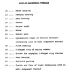
- a groove 32 is formed at an appropriate position in the casting member 24 fixed to an inner surface of the front housing 10, and a C-shaped ring 30 shown in Fig. 4, having an elasticity in a circular direction thereof, is engaged in the groove 32 to retain the front bearing 26 and prevent a movement of same in the longitudinal direction of the motor.
- the front bearing 26 is positioned in the longitudinal direction by the C-shaped ring 30 and a shoulder 38 of the output shaft 18, and the rear bearing 36 is held between the other shoulder 40 of the output shaft 18 and a belleville spring 42 provided in the rear inner housing 34.
- the rear inner housing 34 is made of the same nodular graphite cast iron as the thin cylindrical member 24.
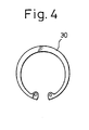
- FIG. 3 shows a cross sectional view of the housing at this stage, i.e., a view taken along a line III-III in Fig. 1 as a longitudinal sectional view of the motor after the assembly is finished, but with the bearing 26 and so on omitted.
- the longitudinal inside end face 46 of the cylindrical casting member 24 is in tight contact with an end-hold portion 44 integrated with the front housing 10 of an aluminum casting.
- the cylindrical casting member 24 is inserted as an insertion member when the aluminum is cast by a die to form the front housing 10, whereby the member is integrated with the front housing 10.
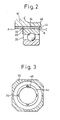
- the cylindrical member 24 must be held by an appropriate jig to maintain the inserted position thereof. Therefore, recessed portions 48 are formed at several positions (four positions in the embodiment) in the end-hold portion 44 as shown in Fig. 3, and the cylindrical member 24 is held by the appropriate jig through the recessed portions 48.
- the recessed portions 48 may be small, i.e., semi-circular recesses having a radius of about 1 mm in the embodiment. In fig. 3, they are shown on an enlarged scale.
- the inner portion of the front housing i.e., the cylindrical casting member 24 is machined with the end-hold portion 44 from a point A to a point C through a point B.
- the depth of the cut is to the same dimension as the recessed portion 48 shown in Fig. 3; namely, about 1 mm.
- finish-machining is carried out to journal the front bearing 26 accurately onto the output shaft 18.
- no burr is generated at the end point B of the inner portion of the housing, even though the cylindrical casting member 24 is made of a ductile material, because the inside end face 46 of the member 24 is in tight contact with the end-hold portion 44.
- the finish-machining is effected also from the points A to C through the point B, and no burr is generated on the end-hold portion 44, because it is made of an aluminum casting and can be freely machined.
- the groove 32 for the C-shaped ring 30 is formed by a machining carried out after the above-mentioned machining. After the C-shaped ring 30 is engaged in the groove, the output shaft 18 with a rotor fixed thereon, and with the front bearing 26 provided thereon, is inserted from the rear of the rear outer housing 14, the rear bearing 36 is mounted on a rear portion of the output shaft 18 from the rear, and finally, the rear inner housing 34 is combined by fixing the belleville spring 42 therebetween.
- a burr is generated when the inner surface of the front housing 10 is finish-machined, a process for removing the burr must be adopted in which the burr is blown off by a compressed air.
- the blown burr may fall into the stator coil 22, to cause a breakdown of the insulation, because the front housing 10 has already been integrated with the stator 16.
- the burr is not removed, insertion of the bearing becomes difficult and has other adverse effects.
- a burr is not generated by the finish-machining, and although the rear inner housing 34 holds the rear bearing 36,.problems such as above-mentioned do not arise because the housing 34 itself is finish-machined before being combined.
- an inner portion of a housing to hold an outer ring of a bearing is made of a ductile material layer containing iron as a main component thereof, a burr is not generated at an edge of the longitudinal end face of the layer when the ductile material layer containing iron as a main component thereof as a hold portion for the bearing is finish-machined after the housings are assembled, because the inside end face of the layer is in tight contact with an end-hold portion integrated with the housing made of a freely cuttable material, and therefore, the stator coil is not damaged and no obstacle arises when the bearing is combined. Accordingly, there can be provided an electrical motor with a high reliability, and a smooth and efficient assembly thereof is attained.
Landscapes
- Engineering & Computer Science (AREA)
- General Engineering & Computer Science (AREA)
- Mechanical Engineering (AREA)
- Power Engineering (AREA)
- Motor Or Generator Frames (AREA)
- Mounting Of Bearings Or Others (AREA)
Abstract
Applications Claiming Priority (2)
| Application Number | Priority Date | Filing Date | Title |
|---|---|---|---|
| JP251997/88 | 1988-10-07 | ||
| JP63251997A JP2598107B2 (ja) | 1988-10-07 | 1988-10-07 | 電動機の軸受保持部構造 |
Publications (2)
| Publication Number | Publication Date |
|---|---|
| EP0406431A1 true EP0406431A1 (fr) | 1991-01-09 |
| EP0406431A4 EP0406431A4 (en) | 1991-04-03 |
Family
ID=17231116
Family Applications (1)
| Application Number | Title | Priority Date | Filing Date |
|---|---|---|---|
| EP19890911104 Withdrawn EP0406431A4 (en) | 1988-10-07 | 1989-10-04 | Bearing retainer structure for electric motors |
Country Status (5)
| Country | Link |
|---|---|
| US (1) | US5166565A (fr) |
| EP (1) | EP0406431A4 (fr) |
| JP (1) | JP2598107B2 (fr) |
| KR (1) | KR900702247A (fr) |
| WO (1) | WO1990004113A1 (fr) |
Cited By (8)
| Publication number | Priority date | Publication date | Assignee | Title |
|---|---|---|---|---|
| FR2796990A1 (fr) * | 1999-07-30 | 2001-02-02 | Valeo Equip Electr Moteur | Element de fermeture du boitier du moteur d'un demarreur de vehicule automobile, et demarreur comportant un tel element de fermeture |
| EP1018796A3 (fr) * | 1999-01-06 | 2001-03-28 | Seiko Epson Corporation | Moteur pas à pas |
| EP0957562A3 (fr) * | 1998-05-12 | 2001-10-04 | Minebea Co., Ltd. | Moteur pas-a-pas |
| WO2007112871A3 (fr) * | 2006-03-29 | 2007-11-22 | Getrag Ford Transmissions Gmbh | Boîte de vitesses à rondelle de compensation |
| WO2013050722A1 (fr) * | 2011-10-06 | 2013-04-11 | Somfy Sas | Bol pour moteur à induction et moteur à induction équipé de ce bol |
| US9837875B2 (en) | 2011-10-06 | 2017-12-05 | Somfy Sas | Induction motor capable of being housed in a tubular actuator and method of assembling this motor |
| CN108005887A (zh) * | 2016-11-30 | 2018-05-08 | 佛山市顺德区美的饮水机制造有限公司 | 隔膜泵电机组件的前盖、隔膜泵电机组件和隔膜泵 |
| GB2563425A (en) * | 2017-06-15 | 2018-12-19 | Avid Tech Limited | Electric propellor drive and vehicle using the same |
Families Citing this family (28)
| Publication number | Priority date | Publication date | Assignee | Title |
|---|---|---|---|---|
| JPH04111260U (ja) * | 1991-03-11 | 1992-09-28 | 東洋電機製造株式会社 | 車両用誘導電動機 |
| JPH0570156U (ja) * | 1992-02-24 | 1993-09-21 | 株式会社富士通ゼネラル | 電動機 |
| JPH0570157U (ja) * | 1992-02-24 | 1993-09-21 | 株式会社富士通ゼネラル | 電動機 |
| JPH0570158U (ja) * | 1992-02-24 | 1993-09-21 | 株式会社富士通ゼネラル | 電動機 |
| JPH0636347U (ja) * | 1992-10-08 | 1994-05-13 | 株式会社富士通ゼネラル | 電動機のブラケット構造 |
| US5705864A (en) * | 1993-07-29 | 1998-01-06 | Canon Kabushiki Kaisha | Stepping motor |
| JP3376057B2 (ja) * | 1993-11-30 | 2003-02-10 | キヤノン株式会社 | ステッピングモータ |
| JPH07184339A (ja) * | 1993-12-24 | 1995-07-21 | Asmo Co Ltd | モータの取付け構造 |
| CN1055352C (zh) * | 1995-06-30 | 2000-08-09 | 谢新茂 | 直流无刷风扇 |
| CN1056020C (zh) * | 1995-10-10 | 2000-08-30 | 谢新茂 | 微小型无刷风扇 |
| US5831360A (en) * | 1995-12-15 | 1998-11-03 | Iai Corporation | Actuator |
| DE19733566B4 (de) * | 1997-08-02 | 2005-10-13 | Minebea Co., Ltd. | Spindelmotor mit Hülse |
| DE19818059B4 (de) * | 1998-04-22 | 2005-06-23 | Interelectric Ag | Wälzlageranordnung für Elektrokleinmotoren |
| US6211587B1 (en) * | 1998-11-12 | 2001-04-03 | Hitachi, Ltd. | Electric rotating machine |
| US6388351B1 (en) | 1999-12-30 | 2002-05-14 | General Electric Company | Bearing load washer |
| JP4417181B2 (ja) * | 2004-06-15 | 2010-02-17 | 三菱電機株式会社 | モータの軸受保持構造 |
| JP2007211639A (ja) * | 2006-02-08 | 2007-08-23 | Hitachi Industrial Equipment Systems Co Ltd | オイルフリースクリュー圧縮機 |
| FR2943863B1 (fr) | 2009-03-31 | 2013-04-12 | Somfy Sas | Moteur a induction de type tubulaire a deux sens de rotation pour applications domotiques. |
| US8278803B2 (en) * | 2009-08-14 | 2012-10-02 | Lin Engineering | Motor end cap positioning element for maintaining rotor-stator concentricity |
| JP5336317B2 (ja) * | 2009-09-25 | 2013-11-06 | Ntn株式会社 | 円すいころ軸受 |
| KR101720536B1 (ko) * | 2010-01-08 | 2017-03-28 | 삼성전자주식회사 | 밀폐형 압축기 |
| US8410643B2 (en) * | 2010-07-22 | 2013-04-02 | Globe Motors, Inc. | Frameless electric motor assembly |
| CN102457142B (zh) * | 2010-10-28 | 2014-07-30 | 比亚迪股份有限公司 | 电机壳的偏心检测装置、导套与电机壳的安装方法 |
| US9874213B2 (en) * | 2012-05-25 | 2018-01-23 | Andrey Yurievich Yazykov | Centrifugal multiple-impeller electric pump |
| DE102015013337A1 (de) * | 2015-10-14 | 2017-04-20 | Nidec Corporation | Bremsmotor |
| US10050490B1 (en) * | 2017-06-01 | 2018-08-14 | Aktiebolaget Skf | Bearing with electric insulators and thermal conductor |
| US10931179B2 (en) | 2018-03-20 | 2021-02-23 | Aktiebolaget Skf | Fiber grounding brush |
| DE102018206242A1 (de) | 2018-04-24 | 2019-10-24 | Aktiebolaget Skf | Wälzlager, das elektrisches Isolierungsmaterial hat, und Herstellungsverfahren eines solchen Wälzlagers |
Family Cites Families (16)
| Publication number | Priority date | Publication date | Assignee | Title |
|---|---|---|---|---|
| FR1153177A (fr) * | 1956-05-04 | 1958-03-03 | Ragonot Ets | Mode de montage de pièces rotatives en porte-à-faux |
| US3214618A (en) * | 1961-06-08 | 1965-10-26 | Eaton Mfg Co | Bearing shunt |
| US3757147A (en) * | 1971-05-18 | 1973-09-04 | Cambridge Thermionic Corp | Stepping motor |
| JPS50111547A (fr) * | 1974-02-15 | 1975-09-02 | ||
| JPS50111547U (fr) * | 1974-02-21 | 1975-09-11 | ||
| DE2427688C2 (de) * | 1974-06-07 | 1984-03-08 | Klöckner-Humboldt-Deutz AG, 5000 Köln | Lagerung von Lageraußenringen bzw. Lagerschalen in einem Leichtmetallgehäuse |
| DE2449455A1 (de) * | 1974-10-19 | 1976-04-22 | Neuweg Fertigung Gmbh | Steh- und flanschlagergehaeuse, die vorzugsweise fuer einstellager (waelzlager) mit kugeligem aussenring verwendung finden |
| US4048530A (en) * | 1975-05-05 | 1977-09-13 | The Superior Electric Company | Electric motor with plastic encapsulated stator |
| JPS5399403A (en) * | 1977-02-12 | 1978-08-30 | Shibaura Eng Works Ltd | Bearing housing of motor bracket |
| JPS58190260A (ja) * | 1982-04-30 | 1983-11-07 | Nippon Radiator Co Ltd | モ−タハウジングの製造方法 |
| JPS58215945A (ja) * | 1982-06-08 | 1983-12-15 | Matsushita Electric Ind Co Ltd | 樹脂モ−ルド電動機 |
| JPS6179069A (ja) * | 1984-09-21 | 1986-04-22 | Aisin Warner Ltd | 車両用変速機のベアリング支持スリ−ブ |
| JPS61109914U (fr) * | 1984-12-24 | 1986-07-11 | ||
| JP2573035B2 (ja) * | 1988-08-24 | 1997-01-16 | 日本電産株式会社 | スピンドルモータ及びスピンドルモータの製造方法 |
| DE3906801A1 (de) * | 1989-03-03 | 1990-09-06 | Kugelfischer G Schaefer & Co | Druckgussgehaeuse |
| JPH06179069A (ja) * | 1992-12-14 | 1994-06-28 | Mitsubishi Materials Corp | 高融点金属部分と低融点金属部分が強固に結合した複合体の製造法 |
-
1988
- 1988-10-07 JP JP63251997A patent/JP2598107B2/ja not_active Expired - Fee Related
-
1989
- 1989-10-04 WO PCT/JP1989/001010 patent/WO1990004113A1/fr not_active Ceased
- 1989-10-04 US US07/490,631 patent/US5166565A/en not_active Expired - Lifetime
- 1989-10-04 EP EP19890911104 patent/EP0406431A4/en not_active Withdrawn
-
1990
- 1990-06-07 KR KR1019900701211A patent/KR900702247A/ko not_active Ceased
Cited By (12)
| Publication number | Priority date | Publication date | Assignee | Title |
|---|---|---|---|---|
| EP0957562A3 (fr) * | 1998-05-12 | 2001-10-04 | Minebea Co., Ltd. | Moteur pas-a-pas |
| EP1018796A3 (fr) * | 1999-01-06 | 2001-03-28 | Seiko Epson Corporation | Moteur pas à pas |
| FR2796990A1 (fr) * | 1999-07-30 | 2001-02-02 | Valeo Equip Electr Moteur | Element de fermeture du boitier du moteur d'un demarreur de vehicule automobile, et demarreur comportant un tel element de fermeture |
| WO2007112871A3 (fr) * | 2006-03-29 | 2007-11-22 | Getrag Ford Transmissions Gmbh | Boîte de vitesses à rondelle de compensation |
| WO2013050722A1 (fr) * | 2011-10-06 | 2013-04-11 | Somfy Sas | Bol pour moteur à induction et moteur à induction équipé de ce bol |
| FR2981222A1 (fr) * | 2011-10-06 | 2013-04-12 | Somfy Sas | Bol pour moteur a induction et moteur a induction equipe de ce bol |
| US9496766B2 (en) | 2011-10-06 | 2016-11-15 | Somfy Sas | Bowl for induction motor and induction motor equipped with said bowl |
| US9837875B2 (en) | 2011-10-06 | 2017-12-05 | Somfy Sas | Induction motor capable of being housed in a tubular actuator and method of assembling this motor |
| EP2764609B1 (fr) * | 2011-10-06 | 2021-08-11 | Somfy Activites Sa | Moteur a induction loge dans un actionneur tubulaire et procede d'assemblage de ce moteur |
| CN108005887A (zh) * | 2016-11-30 | 2018-05-08 | 佛山市顺德区美的饮水机制造有限公司 | 隔膜泵电机组件的前盖、隔膜泵电机组件和隔膜泵 |
| GB2563425A (en) * | 2017-06-15 | 2018-12-19 | Avid Tech Limited | Electric propellor drive and vehicle using the same |
| GB2563425B (en) * | 2017-06-15 | 2021-10-06 | Avid Tech Limited | Electric propellor drive and vehicle using the same |
Also Published As
| Publication number | Publication date |
|---|---|
| JP2598107B2 (ja) | 1997-04-09 |
| JPH02179238A (ja) | 1990-07-12 |
| EP0406431A4 (en) | 1991-04-03 |
| WO1990004113A1 (fr) | 1990-04-19 |
| US5166565A (en) | 1992-11-24 |
| KR900702247A (ko) | 1990-12-06 |
Similar Documents
| Publication | Publication Date | Title |
|---|---|---|
| US5166565A (en) | Hold structure for bearing in electrical motor | |
| JP3718541B2 (ja) | 籠形回転子 | |
| US4339873A (en) | Method of making rotor of rotary machines | |
| EP1367692B1 (fr) | Structure du stator pour un capteur de rotation | |
| JP2008283759A (ja) | モータ、およびモータの製造方法 | |
| EP2019208A1 (fr) | Pompe à vide | |
| US4504754A (en) | Electric motor | |
| EP0595070A1 (fr) | Ensemble de broche de meulage | |
| US20060163955A1 (en) | Flat hollow brushless servo motor with tool mounting hole | |
| JP2002017063A (ja) | モータ及びその製造方法 | |
| JP3541325B2 (ja) | 動圧軸受装置 | |
| JP2001268859A (ja) | 高速回転スピンドル装置 | |
| CN216086283U (zh) | 一体式的转子轴套和具有其的盘式电机 | |
| US5924798A (en) | Hydrodynamic bearing apparatus and method for manufacturing thereof | |
| JP2003204651A (ja) | スピンドルモータ | |
| JP7780168B2 (ja) | モータ軸構造 | |
| JP2530340Y2 (ja) | 2モータ内蔵型スピンドル装置 | |
| JPS59110921A (ja) | 玉軸受装置 | |
| JPH07115746A (ja) | ブラケットを備える回転電機 | |
| JPH0750859Y2 (ja) | 直流機 | |
| JPH05209615A (ja) | 軸受保持装置 | |
| JP2517557Y2 (ja) | 主軸装置の静圧軸受 | |
| KR200144589Y1 (ko) | 모터 | |
| GB2273003A (en) | Miniature motor commutator having noise reduction construction | |
| JP7135786B2 (ja) | 固定子、磁気軸受、回転機械 |
Legal Events
| Date | Code | Title | Description |
|---|---|---|---|
| PUAI | Public reference made under article 153(3) epc to a published international application that has entered the european phase |
Free format text: ORIGINAL CODE: 0009012 |
|
| 17P | Request for examination filed |
Effective date: 19900621 |
|
| AK | Designated contracting states |
Kind code of ref document: A1 Designated state(s): DE FR GB |
|
| A4 | Supplementary search report drawn up and despatched |
Effective date: 19910215 |
|
| AK | Designated contracting states |
Kind code of ref document: A4 Designated state(s): DE FR GB |
|
| RHK1 | Main classification (correction) |
Ipc: F16C 35/06 |
|
| 17Q | First examination report despatched |
Effective date: 19930427 |
|
| STAA | Information on the status of an ep patent application or granted ep patent |
Free format text: STATUS: THE APPLICATION IS DEEMED TO BE WITHDRAWN |
|
| 18D | Application deemed to be withdrawn |
Effective date: 19930908 |