EP0407276A2 - Vorrichtung zum Abgeben und Zerstäuben einer Dosis eines zerteilbaren Produkts - Google Patents
Vorrichtung zum Abgeben und Zerstäuben einer Dosis eines zerteilbaren Produkts Download PDFInfo
- Publication number
- EP0407276A2 EP0407276A2 EP90401881A EP90401881A EP0407276A2 EP 0407276 A2 EP0407276 A2 EP 0407276A2 EP 90401881 A EP90401881 A EP 90401881A EP 90401881 A EP90401881 A EP 90401881A EP 0407276 A2 EP0407276 A2 EP 0407276A2
- Authority
- EP
- European Patent Office
- Prior art keywords
- chamber
- piston
- partition
- wall
- tearable
- Prior art date
- Legal status (The legal status is an assumption and is not a legal conclusion. Google has not performed a legal analysis and makes no representation as to the accuracy of the status listed.)
- Withdrawn
Links
- 238000010298 pulverizing process Methods 0.000 title 1
- 238000005192 partition Methods 0.000 claims abstract description 40
- 239000000843 powder Substances 0.000 claims abstract description 18
- 239000007788 liquid Substances 0.000 claims abstract description 16
- 230000002093 peripheral effect Effects 0.000 claims description 33
- 239000007789 gas Substances 0.000 claims description 18
- 238000007789 sealing Methods 0.000 claims description 18
- 238000005507 spraying Methods 0.000 claims description 13
- IJGRMHOSHXDMSA-UHFFFAOYSA-N Atomic nitrogen Chemical compound N#N IJGRMHOSHXDMSA-UHFFFAOYSA-N 0.000 claims description 12
- 239000011324 bead Substances 0.000 claims description 12
- 239000011521 glass Substances 0.000 claims description 9
- 229910052757 nitrogen Inorganic materials 0.000 claims description 6
- 239000007921 spray Substances 0.000 claims description 6
- 239000002775 capsule Substances 0.000 claims description 4
- 239000004020 conductor Substances 0.000 claims description 3
- 230000000694 effects Effects 0.000 claims description 3
- 238000006073 displacement reaction Methods 0.000 claims description 2
- 229910052751 metal Inorganic materials 0.000 claims description 2
- 239000002184 metal Substances 0.000 claims description 2
- 238000002156 mixing Methods 0.000 claims description 2
- 239000000126 substance Substances 0.000 claims description 2
- 230000035515 penetration Effects 0.000 claims 1
- 238000003825 pressing Methods 0.000 description 4
- 235000014443 Pyrus communis Nutrition 0.000 description 3
- 229910052782 aluminium Inorganic materials 0.000 description 3
- XAGFODPZIPBFFR-UHFFFAOYSA-N aluminium Chemical compound [Al] XAGFODPZIPBFFR-UHFFFAOYSA-N 0.000 description 3
- 239000003814 drug Substances 0.000 description 3
- 239000000203 mixture Substances 0.000 description 3
- 210000003811 finger Anatomy 0.000 description 2
- 244000144992 flock Species 0.000 description 2
- 239000002470 thermal conductor Substances 0.000 description 2
- 238000004500 asepsis Methods 0.000 description 1
- 230000001143 conditioned effect Effects 0.000 description 1
- 230000000994 depressogenic effect Effects 0.000 description 1
- 229940079593 drug Drugs 0.000 description 1
- 230000003631 expected effect Effects 0.000 description 1
- 238000004108 freeze drying Methods 0.000 description 1
- 238000012792 lyophilization process Methods 0.000 description 1
- 238000004519 manufacturing process Methods 0.000 description 1
- 239000000463 material Substances 0.000 description 1
- 238000000034 method Methods 0.000 description 1
- 238000004321 preservation Methods 0.000 description 1
- 230000000717 retained effect Effects 0.000 description 1
- 239000002904 solvent Substances 0.000 description 1
- 238000000859 sublimation Methods 0.000 description 1
- 230000008022 sublimation Effects 0.000 description 1
- 238000010408 sweeping Methods 0.000 description 1
- 210000003813 thumb Anatomy 0.000 description 1
- XLYOFNOQVPJJNP-UHFFFAOYSA-N water Substances O XLYOFNOQVPJJNP-UHFFFAOYSA-N 0.000 description 1
Images


Classifications
-
- B—PERFORMING OPERATIONS; TRANSPORTING
- B05—SPRAYING OR ATOMISING IN GENERAL; APPLYING FLUENT MATERIALS TO SURFACES, IN GENERAL
- B05B—SPRAYING APPARATUS; ATOMISING APPARATUS; NOZZLES
- B05B11/00—Single-unit hand-held apparatus in which flow of contents is produced by the muscular force of the operator at the moment of use
- B05B11/01—Single-unit hand-held apparatus in which flow of contents is produced by the muscular force of the operator at the moment of use characterised by the means producing the flow
- B05B11/06—Gas or vapour producing the flow, e.g. from a compressible bulb or air pump
- B05B11/062—Gas or vapour producing the flow, e.g. from a compressible bulb or air pump designed for spraying particulate material
-
- A—HUMAN NECESSITIES
- A61—MEDICAL OR VETERINARY SCIENCE; HYGIENE
- A61M—DEVICES FOR INTRODUCING MEDIA INTO, OR ONTO, THE BODY; DEVICES FOR TRANSDUCING BODY MEDIA OR FOR TAKING MEDIA FROM THE BODY; DEVICES FOR PRODUCING OR ENDING SLEEP OR STUPOR
- A61M15/00—Inhalators
- A61M15/0001—Details of inhalators; Constructional features thereof
- A61M15/0021—Mouthpieces therefor
- A61M15/0025—Mouthpieces therefor with caps
-
- A—HUMAN NECESSITIES
- A61—MEDICAL OR VETERINARY SCIENCE; HYGIENE
- A61M—DEVICES FOR INTRODUCING MEDIA INTO, OR ONTO, THE BODY; DEVICES FOR TRANSDUCING BODY MEDIA OR FOR TAKING MEDIA FROM THE BODY; DEVICES FOR PRODUCING OR ENDING SLEEP OR STUPOR
- A61M15/00—Inhalators
- A61M15/0028—Inhalators using prepacked dosages, one for each application, e.g. capsules to be perforated or broken-up
- A61M15/003—Inhalators using prepacked dosages, one for each application, e.g. capsules to be perforated or broken-up using capsules, e.g. to be perforated or broken-up
- A61M15/0033—Details of the piercing or cutting means
- A61M15/0035—Piercing means
- A61M15/0036—Piercing means hollow piercing means
-
- B—PERFORMING OPERATIONS; TRANSPORTING
- B05—SPRAYING OR ATOMISING IN GENERAL; APPLYING FLUENT MATERIALS TO SURFACES, IN GENERAL
- B05B—SPRAYING APPARATUS; ATOMISING APPARATUS; NOZZLES
- B05B11/00—Single-unit hand-held apparatus in which flow of contents is produced by the muscular force of the operator at the moment of use
- B05B11/01—Single-unit hand-held apparatus in which flow of contents is produced by the muscular force of the operator at the moment of use characterised by the means producing the flow
- B05B11/06—Gas or vapour producing the flow, e.g. from a compressible bulb or air pump
-
- A—HUMAN NECESSITIES
- A61—MEDICAL OR VETERINARY SCIENCE; HYGIENE
- A61M—DEVICES FOR INTRODUCING MEDIA INTO, OR ONTO, THE BODY; DEVICES FOR TRANSDUCING BODY MEDIA OR FOR TAKING MEDIA FROM THE BODY; DEVICES FOR PRODUCING OR ENDING SLEEP OR STUPOR
- A61M2202/00—Special media to be introduced, removed or treated
- A61M2202/06—Solids
- A61M2202/064—Powder
-
- A—HUMAN NECESSITIES
- A61—MEDICAL OR VETERINARY SCIENCE; HYGIENE
- A61M—DEVICES FOR INTRODUCING MEDIA INTO, OR ONTO, THE BODY; DEVICES FOR TRANSDUCING BODY MEDIA OR FOR TAKING MEDIA FROM THE BODY; DEVICES FOR PRODUCING OR ENDING SLEEP OR STUPOR
- A61M2205/00—General characteristics of the apparatus
- A61M2205/07—General characteristics of the apparatus having air pumping means
- A61M2205/071—General characteristics of the apparatus having air pumping means hand operated
- A61M2205/073—Syringe, piston type
Definitions
- the present invention relates to a device for projecting and spraying a dose of a divisible product, in liquid or powder, for medical purposes. It is common to have to introduce a powder or liquid medicine into the throat or into the nostrils. The operation is delicate, especially in the nostrils, because you have to tilt your head back. Despite the precautions that can be taken, some of the medicine may fall outside the target. The expected effect cannot be completely obtained, the dosage is random.
- the object of the present invention is a device for expelling the drug in divided form. It can therefore be sent into the throat or nostrils without loss, with maximum efficiency.
- a device for projecting and spraying a dose of a divisible product, in liquid or powder, in particular for pharmaceutical use characterized in that it comprises a container with an outlet orifice , a tearable partition separating the container into two chambers, a first chamber on the side of the outlet orifice intended to receive the divisible product, and a second chamber comprising at the time of use a compressed gas, a means being provided for perforating the partition at the time of use.
- the means for perforating the partition may be a preferably grooved point, integral with a deformable wall. By pressing on the deformable wall, the point is moved which perforates the partition.
- the deformation of the wall can increase or create the gas pressure in the second volume by reducing the latter, the gas being thus compressed when the device is used.
- the deformation of the wall can be obtained by the flexibility of the wall, or the wall can comprise a cylindrical part in which a piston slides. It is advantageous to increase the pressure before perforating the partition.
- the container can be made in one piece.
- the container can be glass or plastic.
- the second chamber can be filled with nitrogen at a pressure at least equal to atmospheric pressure.
- the first chamber can also be filled with nitrogen in addition to the product to be dispersed.
- the container consists of: a piston having an axial hole passing through it, a peripheral groove and a peripheral sealing lip; of a nozzle comprising the outlet orifice and an elastic means which can snap into the groove of the piston, the nozzle and the piston defining a housing capable of receiving a bottle having a side wall and the tearable partition, said bottle representing the 'enclosure of said first chamber containing the product to be sprayed, and a contact surface between the piston and the bottle being sealed; and is characterized in that the deformable wall is a hollow cylinder provided with a bottom and a cylindrical side wall inside which the piston slides so that the sealing lip is in contact with said side wall over a whole periphery, the perforation means being arranged on the bottom of the cylinder so as to be able to pass through the hole of the piston to pierce the tearable partition.
- a spring can urge the plunger so as to move it away from the piston.
- a peripheral bead can optionally be formed on an inner surface of the pusher so that when the device is mounted, the piston can be inserted inside the pusher by forcing the sealing lip to pass over the bead, and that the biasing of the spring plus the tensile force necessary to undo the snap-fastening of the elastic means of the end piece is not enough to make the sealing lip pass over the bead again.
- a first end of a bottle delimiting the first chamber is fitted in a sealed manner with friction at one end of the second chamber, said first end of the bottle being closed by the tearable partition, and a nozzle comprising the outlet orifice is fitted with friction on a second end of the bottle.
- the deformable wall is a piston against which abuts one end of a push rod
- the second chamber being a cylinder adapted to this piston
- a spring can urge the piston so as to move away from the bottle.
- the bottle of the two particular embodiments described above can be made of glass or plastic.
- the tearable partition can be a heat-sealed film. It can be made of a heat conductive material. It can occupy an entire section of the first chamber, so as to have maximum thermal transmissivity.
- the first chamber comprises a cylindrical cup containing a spray powder and consisting of a bottom and a peripheral side wall extending vertically from the bottom, said peripheral side wall comprising in part upper a sealing means fitted in force inside the first chamber, said peripheral lateral wall also comprising at least one non-radial orifice passing through it and directed obliquely inwards and towards the bottom of the cup, said bottom of the cup having a convex conical upper surface, the cup cooperating with the first chamber so as to allow the passage of compressed gas from the interior of the first chamber to the interior of the cup through the orifice (s) without the cup being ejected towards the outside, and the orifice (s) cooperating with said conical surface to create a vortex movement at the same time as the expulsion of the substance to be sprayed, during the passage of the compressed gas.
- the first chamber containing the product to be dispersed has a constant section, and the outlet orifice is of the same section as said first chamber.
- the device can be provided with a plug comprising a cover from which extends a skirt to a lower end, said skirt fitting in a sealed manner with friction in the chamber, and is characterized in that the skirt comprises a slit over part of its height, starting from its lower end.
- a tearable metal capsule can be crimped over the cap.
- the embodiment shown in Figure 1 is a small device which has a body 1, separated into two chambers 1A and 1B by a tearable partition 2.
- the first chamber 1A of small volume, is placed on the side of the orifice outlet 3 which, before use, is normally closed by a plug 4.
- This chamber is provided to receive a powder which can occupy all or part of the volume of the chamber.
- the second chamber 1B is cylindrical and contains a piston 5 provided with a grooved tip 6, arranged so as to come and pierce the partition 2 during the displacement of the piston towards the first chamber.
- the piston is controlled by a pusher 7, with an actuating rod 8.
- the piston can be held inside the cylinder by a peripheral bead 9.
- the body 1 can be molded with a tearable strip 11, guaranteeing inviolability .
- the second chamber 1B can be loaded initially with a certain gas overpressure so as to increase the projection effect.
- the chamber 1B can be filled with nitrogen, at a pressure at least equal to atmospheric pressure, so as to guarantee the purity and asepsis of the gas contained in said chamber 1B.
- Chamber 1A can also be filled with nitrogen in addition to the product to be dispersed.
- the tearable strip 11 can be molded with the pusher 7, which makes it possible to produce the body 1 in glass as well as in plastic.
- This device operates as follows.
- the user After tearing of the strip 11, the user removes the plug 4 and places the device in position for the desired application (for example engagement of the outer end of the first chamber 1A in one nostril). Then, the pusher 7 is depressed over the entire stroke H corresponding substantially to the height of the guarantee strip.
- the point 6 After a movement h, the point 6 has perforated the partition 2 which tears.
- the air (or another gas) compressed by the piston 5, possibly in addition to an initial pressure, is released and quickly passes through the first chamber 1A towards the outlet 3, entraining the powder which is projected outside.
- the hole made in the partition 2 causes a Venturi effect, which promotes the entrainment of the powder by the air.
- the device is discarded after use. Its extremely simple structure allows this application in the medical field.
- the chamber 1A must be smaller than the gas chamber 1B to have a good sweeping of the powder.
- This first chamber 1A will advantageously have a tubular shape without narrowing to promote the entrainment of the powder, not necessarily cylindrical.
- the body 1 has near the pusher 7 a flange to facilitate the grip of the device and its holding during application.
- the tip 6 may have longitudinal grooves or ribs to promote the tearing of the partition 2 and to guarantee the passage of air in the event that said partition does not tear, but is simply perforated.
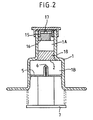
- the apparatus of FIG. 2 differs from that of FIG. 1 only in that it comprises a spray nozzle for a liquid.
- this nozzle consists of a socket 15 which can be welded or glued to the wall of the body 1, and a core is placed inside to cooperate with the outlet hole 17 of the socket 15.
- the chamber 1A is therefore originally filled with liquid, possibly also with a gas.
- the second chamber 1B can comprise a part of liquid and a part of gas. Holding the device with the outlet down, and the piston at the top, when the tip 6 will pierce the seal, the compressed air will drive the liquid from chamber 1B into chamber 1A, the liquids will mix, and the mixture, thus prepared at the time of use, will be expelled by air pressure through the nozzle. It is therefore possible to project a dose consisting of two products, the mixing of which is carried out only at the last moment, before use, and in fact, almost concomitantly.
- the tip 6 may be close to the partition 2, and the second chamber 1B initially contains no gas under pressure. Thus, with a slight movement of the pusher, the partition is pierced; you can then shake the device to mix the two liquids, and then press the button to project the mixture.
- FIG. 3 represents a variant in which the deformable wall is constituted by a substantially hemispherical wall 21, made of flexible material, similar to a pear.
- the wide end of the rod 8 comes to press on the pear.
- the crushing of the pear causes the pressure to rise, before the point 6 pierces the partition 2.
- the peripheral edge 21A of the flexible wall 21 can be glued or welded to the body of the container 1.
- This wall can be molded in one piece with the tip 6. This gives a high quality seal, and gas, air or other can be contained for a long time in the chamber 1B, without appreciable losses.
- the pusher 7 and its rod 8 can also be molded in one piece with the wall 21 and the tip 6, or can be surmounted on this wall.
- FIGS 4, 4a and 5 show an embodiment of the invention in which the spraying device is rechargeable and more particularly intended for spraying lyophilisates.
- This device is broken down into: a pusher 30 comprising a cylindrical bottom 31, itself comprising an interior face, an exterior face and an exterior peripheral edge, said pusher 30 also comprising a cylindrical side wall 32 extending upwards from said exterior peripheral edge, said cylindrical side wall 32 itself comprising a substantially cylindrical inner surface, a cylindrical outer surface and an upper end.
- a cylindrical shoulder 33 is formed on the inner face of the bottom 31, substantially centered on this inner face. On the shoulder 33 is made a grooved tip 6.
- the inner surface of the cylindrical side wall 32 comprises in the upper part a peripheral bead 9; a piston 40 of generally cylindrical shape, adapted to slide vertically inside said cylindrical side wall 32, comprising an upper face, a lower face and a substantially cylindrical peripheral surface 44.
- a cylindrical hole 41 substantially coaxial with the piston 40 passes through said piston from top to bottom and is dimensioned to allow the grooved tip 6 to pass when the piston slides downwards.
- a cylindrical housing 42 is formed in the upper face of the piston, substantially coaxial with the cylindrical hole 41, extending downward from said upper face to a flat annular surface 46.
- a peripheral groove 43 is formed in the upper part of the cylindrical peripheral surface 44. Said peripheral surface 44 is extended downwards and outwards by a peripheral sealing lip 45 pressing against the interior surface of the cylindrical side wall 32.
- the sealing lip 45 is such that the piston 40 can be inserted inside the pusher 30 by forcing the sealing lip 45 to pass over the peripheral bead 9 during assembly of the device, without damaging said sealing lip 45; a substantially helical spring 34 placed inside the pusher 30, fitted on and retained by the cylindrical shoulder 33, and adapted to push the piston 40 upwards.
- the stiffness of the spring 34 is such that it can be compressed with the force of the fingers of a user, and that it cannot force the sealing lip 45 of the piston 40 to pass over the peripheral flange 9 of the pusher 30;
- a bottle 50 of cylindrical shape comprising a cylindrical side wall, made of glass or plastic, itself composed of an upper face, a flat lower end face 52, a cylindrical outer surface and a cylindrical inner surface.
- the bottle 50 also includes a tearable partition 2 advantageously consisting of a heat-sealed film on the flat lower end face 52 of the cylindrical side wall 51. Said bottle 50 is inserted in the cylindrical housing 42.
- the interior of said bottle 50 delimits the chamber 1A, chamber 1B being delimited by the pusher 30, the piston 40 associated with the pusher 30 by the sealing lip 45, and the tearable partition 2 coming into contact with the annular horizontal face 46; -
- a tip 60 of axial symmetry coming to cover all of the components described above, comprising an orifice 3, a cylindrical interior housing 61 in which is housed the bottle 50, at least three arms 62 extending downward and provided at their lower end with a lug 63 adapted to snap into the peripheral groove 43 of the piston 40 without the force necessary for latching substantially compressing the spring 34, and such that the tensile force necessary to undo the snap-fastening is not sufficient to cause the sealing lip 45 of the piston to pass over the peripheral bead 9, said end piece 60 also comprising a
- the piston 40, the bottle 50 and the nozzle 60 are configured and dimensioned so that when the arms 62 are snapped into the peripheral groove 43, the lower end face 52 of the cylindrical side wall 51 and the heat-sealed film which is integral with the end face 52 are applied against the annular horizontal surface 46 of the piston 40 so as to provide a seal.
- the chamber 1B is sealed.
- a user When a user wishes to spray a dose of product, he takes a bottle 50 as shown in FIG. 5, that is to say comprising a stopper 4 and a tearable capsule 99 so that it can be stored. The user then removes the capsule 99 and the stopper 4, places the bottle 50 in the housing 42 of the piston 40, then caps the assembly using the end piece 60 by snapping the lugs 63 of the arms 62 into the groove peripheral 43 of the piston 40. The device is then ready to be used. The spraying is done by holding the tip 60 between the index and middle fingers, and pressing the pusher 30 with the thumb. The thrust first compresses the air included in the chamber 1B, then the grooved point 6 pierces the tearable partition 2.
- the compressed air in the chamber 1B then rushes into the chamber 1A, and sprays the lyophilisate contained in bedroom 1A.
- the lyophilisate Before spraying, the lyophilisate is in an agglomerated form; it is the violence of the projection by compressed air which puts it in powder form. Therefore, it is essential that the bottle 50 does not shrink and that the orifice 3 is at least as wide as the interior of the bottle 50, so as to avoid engorgement of the orifice by the lyophilisate, and therefore improper spraying or impossible spraying of the product.
- the spring 34 After spraying, the spring 34 returns the piston to its initial position, the nozzle 60 is removed from the assembly by a simple pull, and the empty bottle 50 is discarded. The other components of the assembly can then be reused with a new bottle 50.
- the bottle 50 and its tearable partition 2 are good thermal conductors; preferably, the bottle will therefore be made of glass, a better conductor than plastic, and the tearable partition will be made of an aluminum complex. Since the aluminum complex is a better thermal conductor than glass, it is advantageous to give the partition 2 the largest possible surface.
- the bottle 50 is provided with a stopper 4 comprising a cover from which extends a cylindrical skirt to a lower end.
- the skirt has a slot 4a over part of its height, starting from its lower end.
- the stopper 4 is partially engaged, so as to make the chamber 1A communicate with the outside through the slot 4a.
- the stopper 4 is fully engaged while the bottle is still under vacuum, which closes the chamber 1A.
- FIG. 6 and 7 The embodiment shown in Figures 6 and 7 is intended for spraying powders, that is to say products stored in powder form.
- the cylindrical side wall 51 of the bottle 50 comprises a cylindrical housing extending from the upper end face downward, to a horizontal annular surface 55, said housing defining a cylindrical interior surface 57; and - Said cylindrical housing receives a cylindrical cup 53 comprising a bottom, itself composed of a cylindrical peripheral surface of dimension smaller than the diameter of the cylindrical interior surface 57, of a substantially planar lower surface and provided with ribs 54 at a periphery outer, and a convex conical upper surface 70.
- the ribs 54 rest on the horizontal annular surface 55 so as to leave a passage between said cup 53 and the annular surface 55.
- the cup 53 also has a cylindrical side wall extending from from said bottom upward, and having a cylindrical inner surface, a cylindrical outer surface and an upper end.
- the inner surface of the cylindrical side wall and the upper surface of the bottom define a chamber 1A ′ containing the powder to spray.
- the cylindrical side wall of the cup 53 has an outside diameter less than the diameter of the cylindrical interior surface 57.
- One or more non-radial orifices 58 pass through said cylindrical side wall of the cup 53, diagonally inward of the cup and towards the bottom, opening into the interior of said cup near the base of the convex conical surface 70.
- the cylindrical side wall also includes, in the upper part of its outer surface, a peripheral sealing lip 59, dimensioned and configured to be fitted in force inside the surface 57, so that, when compressed air enters the bottle 50 after piercing the tearable partition 2, the cup 53 is not ejected to the outside.
- the bottle 50 and the cup 53 are moreover held in place by the end piece 60.
- the compressed air then passes between the ribs 54, then enters an annular space comprised between the cup 53 and the interior surface 57, and enters the chamber 1A ′ via the orifice (s) 58 whose arrangement relative to the convex conical surface 70 causes a vortex movement at the same time as the expulsion of the powder included in the chamber 1A ′.
- the chamber 1B is formed by a cylinder 81 in which slides a piston 5.
- the piston 5 fits tightly on a rod 8 of a pusher 7, in abutment against a collar 8a of the rod.
- the rod 8 is extended beyond the piston by a point 6 provided with grooves 84.
- the cylinder 81 has at one end a bottom 82 crossed by a hollow tube 83 in which the point 6 is adapted to slide.
- a spring 34 is supported on the bottom 82 and on the piston 5, so as to move the piston away from the bottom.
- An inner peripheral bead 9 is formed at a lower end of the cylinder 81, so as to prevent the piston 5 from coming out of the cylinder.
- the tube 83 has, at an upper end, a housing adapted to receive a cylindrical bottle 50 as described in the embodiment of FIG. 5, by carrying out a sealed fitting.
- an end piece 80 comprising the outlet orifice 3 fits onto the bottle 50.
- the orifice 3 is preferably of the same width as the chamber 1A, delimited by the bottle 50.
- the end piece 80 is extended radially outwards by a flange facilitating the grip.
- the piston 5 compresses the air contained in the chamber 1B until the point 6 pierces the tearable partition 2. The compressed air in the chamber 1B then escapes through grooves 84 of the tip 6 by spraying the lyophilisate contained in the chamber 1A. At the end of the race, the piston 5 abuts against one end of the tube 83 by means of ribs 85, which allow free passage between the chamber 1A and the chamber 1B. When the user releases his push, the piston 5 returns to its initial position.
Landscapes
- Health & Medical Sciences (AREA)
- Engineering & Computer Science (AREA)
- Bioinformatics & Cheminformatics (AREA)
- Pulmonology (AREA)
- Anesthesiology (AREA)
- Biomedical Technology (AREA)
- Heart & Thoracic Surgery (AREA)
- Hematology (AREA)
- Life Sciences & Earth Sciences (AREA)
- Animal Behavior & Ethology (AREA)
- General Health & Medical Sciences (AREA)
- Public Health (AREA)
- Veterinary Medicine (AREA)
- Containers And Packaging Bodies Having A Special Means To Remove Contents (AREA)
- Medical Preparation Storing Or Oral Administration Devices (AREA)
- Nozzles (AREA)
Applications Claiming Priority (2)
| Application Number | Priority Date | Filing Date | Title |
|---|---|---|---|
| FR8908971A FR2649323B1 (fr) | 1989-07-04 | 1989-07-04 | Dispositif de projection et de pulverisation d'une dose d'un produit divisable |
| FR8908971 | 1989-07-04 |
Publications (2)
| Publication Number | Publication Date |
|---|---|
| EP0407276A2 true EP0407276A2 (de) | 1991-01-09 |
| EP0407276A3 EP0407276A3 (en) | 1991-11-27 |
Family
ID=9383450
Family Applications (1)
| Application Number | Title | Priority Date | Filing Date |
|---|---|---|---|
| EP19900401881 Withdrawn EP0407276A3 (en) | 1989-07-04 | 1990-06-29 | Dispensing and pulverizing apparatus for a dose of a divisible product |
Country Status (4)
| Country | Link |
|---|---|
| EP (1) | EP0407276A3 (de) |
| JP (1) | JPH03131271A (de) |
| CA (1) | CA2020425A1 (de) |
| FR (1) | FR2649323B1 (de) |
Cited By (31)
| Publication number | Priority date | Publication date | Assignee | Title |
|---|---|---|---|---|
| WO1993011818A1 (en) * | 1991-12-10 | 1993-06-24 | Novo Nordisk A/S | Disposable dispenser for drugs |
| US5307953A (en) * | 1991-12-03 | 1994-05-03 | Glaxo Group Limited | Single dose dispenser having a piercing member |
| DE4412041A1 (de) * | 1994-04-08 | 1995-10-12 | Pfeiffer Erich Gmbh & Co Kg | Austragvorrichtung für fließfähige Medien, insbesondere für den Austrag in nur einem Hub |
| DE19637101A1 (de) * | 1996-09-12 | 1998-03-19 | Pfeiffer Erich Gmbh & Co Kg | Austragvorrichtung für Medien |
| US5819730A (en) * | 1993-06-09 | 1998-10-13 | Glaxo Wellcome Australia Ltd. | Device for administering pharmaceutical substances |
| WO1999046055A1 (fr) * | 1998-03-10 | 1999-09-16 | Valois S.A. | Reservoir, procede de remplissage du reservoir et dispositif de distribution du produit fluide contenu dans le reservoir |
| FR2780388A1 (fr) | 1998-06-24 | 1999-12-31 | Valois Sa | Reservoir de produit pulverulent et procede de remplissage d'un tel reservoir |
| US6119688A (en) * | 1991-08-26 | 2000-09-19 | 3M Innovative Properties Company | Powder dispenser |
| US6189739B1 (en) | 1996-06-01 | 2001-02-20 | Astrazeneca Ab | Pump dispenser with threshold actuation and restoring spring |
| GB2367756A (en) * | 2000-10-12 | 2002-04-17 | Bespak Plc | Disposable dispensing apparatus including a frangible membrane |
| EP1329237A1 (de) * | 2002-01-22 | 2003-07-23 | Bespak Plc | Abgabevorrichtung |
| WO2003080163A1 (en) * | 2002-03-20 | 2003-10-02 | Advanced Inhalation Research, Inc. | Puncturing means for use in an inhalation device |
| WO2004004922A1 (en) * | 2002-07-09 | 2004-01-15 | Optinose As | Delivery devices |
| US6732732B2 (en) | 2001-04-16 | 2004-05-11 | Advanced Inhalation Research, Inc. | Inhalation device and method |
| WO2004054555A1 (ja) | 2001-06-15 | 2004-07-01 | Otsuka Pharmaceutical Co., Ltd. | 新しい経肺投与用乾燥粉末吸入システム |
| GB2412326A (en) * | 2004-03-26 | 2005-09-28 | Bespak Plc | Hand-held dispenser |
| US7086571B2 (en) | 2001-04-30 | 2006-08-08 | Bespak Plc | Valves for pressurized dispensing containers |
| US7455248B2 (en) | 2004-03-17 | 2008-11-25 | Genzyme Corporation | Powder delivery device |
| US7491194B1 (en) | 2004-02-03 | 2009-02-17 | David Oliwa | Remote control valve for urine collection bag |
| CN101366989B (zh) * | 2001-06-15 | 2012-03-21 | 大塚制药株式会社 | 经肺给药用干燥粉末吸入系统 |
| US8496002B2 (en) | 2007-06-12 | 2013-07-30 | Civitas Therapeutics, Inc. | Powder inhaler devices |
| US8550074B2 (en) | 2009-01-15 | 2013-10-08 | Manta Devices, Llc | Delivery device and related methods |
| US8607787B2 (en) | 2007-07-06 | 2013-12-17 | Manta Devices, Llc | Dose delivery device for inhalation |
| US8763605B2 (en) | 2005-07-20 | 2014-07-01 | Manta Devices, Llc | Inhalation device |
| US9283336B2 (en) | 2010-03-19 | 2016-03-15 | Manta Devices, Llc | Delivery device and related methods |
| US9649454B2 (en) | 2012-05-03 | 2017-05-16 | Manta Devices, Llc | Delivery device and related methods |
| US11103659B2 (en) | 2011-07-06 | 2021-08-31 | Manta Devices, Llc | Delivery device and related methods |
| US11147936B2 (en) | 2014-05-02 | 2021-10-19 | Manta Devices, Llc | Dose delivery device with cover connected to dose chamber seal |
| US11224704B2 (en) | 2007-07-06 | 2022-01-18 | Manta Devices, Llc | Dose delivery device for inhalation |
| EP3884980A4 (de) * | 2018-11-19 | 2022-08-17 | Shin Nippon Biomedical Laboratories, Ltd. | Medikamentenabgabevorrichtung und verfahren zu ihrer herstellung |
| FR3121047A1 (fr) | 2021-03-29 | 2022-09-30 | Aptar France Sas | Dispositif de distribution nasale de poudre |
Families Citing this family (6)
| Publication number | Priority date | Publication date | Assignee | Title |
|---|---|---|---|---|
| US5337740A (en) * | 1991-08-01 | 1994-08-16 | New England Pharmaceuticals, Inc. | Inhalation devices |
| US5411175A (en) * | 1993-03-08 | 1995-05-02 | New England Pharmaceuticals, Inc. | Cartridges, devices and methods for dispensing liquids |
| RU2207885C2 (ru) * | 1995-08-30 | 2003-07-10 | Фармация Аб | Способ подачи небольшого объема лечебного раствора к целевому месту |
| US20150041496A1 (en) * | 2013-08-08 | 2015-02-12 | Sungmoon Kim | Single use enhancement for dispenser assembly |
| FR3098407B1 (fr) * | 2019-07-10 | 2024-12-13 | Aptar France Sas | Dispositif de distribution nasale de poudre |
| WO2022049136A1 (en) * | 2020-09-01 | 2022-03-10 | Janssen Pharmaceutica Nv | Drug delivery systems and methods and drug products |
Family Cites Families (9)
| Publication number | Priority date | Publication date | Assignee | Title |
|---|---|---|---|---|
| BE333199A (de) * | 1925-04-17 | |||
| FR40182E (fr) * | 1931-05-06 | 1932-06-07 | Vincent Jean | Pulvérisateur perfectionné |
| US2533065A (en) * | 1947-03-08 | 1950-12-05 | George V Taplin | Micropulverized therapeutic agents |
| CH518744A (de) * | 1970-01-30 | 1972-02-15 | Ciba Geigy Ag | Vorrichtung zur Applikation von pulverförmigen Substanzen |
| US3949751A (en) * | 1970-03-03 | 1976-04-13 | Fisons Limited | Method and device for dispensing medicament to the body |
| SE7415243L (de) * | 1973-12-26 | 1975-06-27 | Ciba Geigy Ag | |
| FR2294937A1 (fr) * | 1974-12-18 | 1976-07-16 | Neve Rene | Flacon a deux compartiments |
| US4093124A (en) * | 1976-07-26 | 1978-06-06 | L'oreal | Atomizer with air inlet valve |
| FR2622546B2 (fr) * | 1987-05-25 | 1990-03-16 | Emballages Conseils Etudes | Dispositif de fermeture pour recipients |
-
1989
- 1989-07-04 FR FR8908971A patent/FR2649323B1/fr not_active Expired - Fee Related
-
1990
- 1990-06-29 EP EP19900401881 patent/EP0407276A3/fr not_active Withdrawn
- 1990-07-04 JP JP17720790A patent/JPH03131271A/ja active Pending
- 1990-07-04 CA CA 2020425 patent/CA2020425A1/en not_active Abandoned
Cited By (62)
| Publication number | Priority date | Publication date | Assignee | Title |
|---|---|---|---|---|
| US6119688A (en) * | 1991-08-26 | 2000-09-19 | 3M Innovative Properties Company | Powder dispenser |
| US5307953A (en) * | 1991-12-03 | 1994-05-03 | Glaxo Group Limited | Single dose dispenser having a piercing member |
| AU661095B2 (en) * | 1991-12-10 | 1995-07-13 | Novo Nordisk A/S | Dispenser |
| WO1993011818A1 (en) * | 1991-12-10 | 1993-06-24 | Novo Nordisk A/S | Disposable dispenser for drugs |
| US5819730A (en) * | 1993-06-09 | 1998-10-13 | Glaxo Wellcome Australia Ltd. | Device for administering pharmaceutical substances |
| DE4412041A1 (de) * | 1994-04-08 | 1995-10-12 | Pfeiffer Erich Gmbh & Co Kg | Austragvorrichtung für fließfähige Medien, insbesondere für den Austrag in nur einem Hub |
| US6189739B1 (en) | 1996-06-01 | 2001-02-20 | Astrazeneca Ab | Pump dispenser with threshold actuation and restoring spring |
| EP0829307A3 (de) * | 1996-09-12 | 1998-09-02 | Ing. Erich Pfeiffer GmbH | Spender für Medien |
| US5967369A (en) * | 1996-09-12 | 1999-10-19 | Ing. Erich Pfeiffer Gmbh | Dispenser for media having measured reservoir |
| DE19637101A1 (de) * | 1996-09-12 | 1998-03-19 | Pfeiffer Erich Gmbh & Co Kg | Austragvorrichtung für Medien |
| WO1999046055A1 (fr) * | 1998-03-10 | 1999-09-16 | Valois S.A. | Reservoir, procede de remplissage du reservoir et dispositif de distribution du produit fluide contenu dans le reservoir |
| US6398074B1 (en) | 1998-03-10 | 2002-06-04 | Valois S.A. | Reservoir, reservoir filling method and device for dispensing fluid contained in the reservoir |
| CN1106888C (zh) * | 1998-03-10 | 2003-04-30 | 瓦卢瓦股份有限公司 | 容器、容器的灌注方法及容器中流体制品的分配装置 |
| FR2780388A1 (fr) | 1998-06-24 | 1999-12-31 | Valois Sa | Reservoir de produit pulverulent et procede de remplissage d'un tel reservoir |
| US6866039B1 (en) | 2000-10-12 | 2005-03-15 | Bespak Plc | Dispensing apparatus |
| GB2367756A (en) * | 2000-10-12 | 2002-04-17 | Bespak Plc | Disposable dispensing apparatus including a frangible membrane |
| GB2367756B (en) * | 2000-10-12 | 2003-01-08 | Bespak Plc | Dispensing apparatus |
| US7278425B2 (en) | 2001-04-16 | 2007-10-09 | Alkermes, Inc. | Inhalation device and method |
| US6732732B2 (en) | 2001-04-16 | 2004-05-11 | Advanced Inhalation Research, Inc. | Inhalation device and method |
| US7086571B2 (en) | 2001-04-30 | 2006-08-08 | Bespak Plc | Valves for pressurized dispensing containers |
| AP1861A (en) * | 2001-06-15 | 2008-07-02 | Otsuka Pharma Co Ltd | Dry powder inhalation system for transpulmonary administration |
| US8333193B2 (en) | 2001-06-15 | 2012-12-18 | Otsuka Pharmaceutical Co., Ltd. | Dry powder inhalation system for transpulmonary administration |
| WO2004054555A1 (ja) | 2001-06-15 | 2004-07-01 | Otsuka Pharmaceutical Co., Ltd. | 新しい経肺投与用乾燥粉末吸入システム |
| US8443799B2 (en) | 2001-06-15 | 2013-05-21 | Otsuka Pharmaceutical Co., Ltd. | Dry powder inhalation system for transpulmonary administration |
| EP1402913A4 (de) * | 2001-06-15 | 2004-12-01 | Otsuka Pharma Co Ltd | Trockenpulver-inhalationssystem für die transpulmonale verabreichung |
| CN101366989B (zh) * | 2001-06-15 | 2012-03-21 | 大塚制药株式会社 | 经肺给药用干燥粉末吸入系统 |
| EP1688133A1 (de) * | 2001-06-15 | 2006-08-09 | Otsuka Pharmaceutical Co., Ltd. | Gefriergetrocknete Zusammensetzung für transpulmonäre Verabreichung |
| AU2008200583B2 (en) * | 2001-06-15 | 2011-05-19 | Otsuka Pharmaceutical Co., Ltd. | Dry powder inhalation system for transpulmonary administration |
| HRP20040033B1 (en) * | 2001-06-15 | 2007-11-30 | Otsuka Pharmaceutical Co. | Dry powder inhalation system for transpulmonary administration |
| AU2002311213B2 (en) * | 2001-06-15 | 2007-12-13 | Otsuka Pharmaceutical Co., Ltd. | Dry powder inhalation system for transpulmonary administration |
| US7735485B2 (en) | 2001-06-15 | 2010-06-15 | Otsuka Pharmaceutical Co., Ltd. | Dry powder inhalation system for transpulmonary administration |
| CN100427077C (zh) * | 2001-06-15 | 2008-10-22 | 大塚制药株式会社 | 经肺给药用干燥粉末吸入系统 |
| US7448379B2 (en) | 2001-06-15 | 2008-11-11 | Otsuka Pharmaceutical Co., Ltd. | Composition, vessel, dry powder inhalation system, and related methods for transpulmonary administration |
| EP1688134A3 (de) * | 2001-06-15 | 2009-11-18 | Otsuka Pharmaceutical Co., Ltd. | Trockenpulver-Inhalationssystem für die transpulmonale Verabreichung |
| EP1579855A4 (de) * | 2001-06-15 | 2009-11-04 | Otsuka Pharma Co Ltd | Neues trockenpulver-inhalationssystem für transpulmonale verabreichung |
| US6945953B2 (en) | 2002-01-22 | 2005-09-20 | Bespak Plc | Dispensing apparatus for delivering powdered product |
| EP1329237A1 (de) * | 2002-01-22 | 2003-07-23 | Bespak Plc | Abgabevorrichtung |
| WO2003080163A1 (en) * | 2002-03-20 | 2003-10-02 | Advanced Inhalation Research, Inc. | Puncturing means for use in an inhalation device |
| WO2004004922A1 (en) * | 2002-07-09 | 2004-01-15 | Optinose As | Delivery devices |
| US7934503B2 (en) | 2002-07-09 | 2011-05-03 | Optinose As | Delivery devices |
| US7491194B1 (en) | 2004-02-03 | 2009-02-17 | David Oliwa | Remote control valve for urine collection bag |
| US7455248B2 (en) | 2004-03-17 | 2008-11-25 | Genzyme Corporation | Powder delivery device |
| GB2412326A (en) * | 2004-03-26 | 2005-09-28 | Bespak Plc | Hand-held dispenser |
| US12343469B2 (en) | 2005-07-20 | 2025-07-01 | Manta Devices, Llc | Inhalation device |
| US8763605B2 (en) | 2005-07-20 | 2014-07-01 | Manta Devices, Llc | Inhalation device |
| US11672927B2 (en) | 2005-07-20 | 2023-06-13 | Manta Devices, Llc | Inhalation device |
| US11491287B2 (en) | 2005-07-20 | 2022-11-08 | Manta Devices, Llc | Inhalation device |
| US10632268B2 (en) | 2005-07-20 | 2020-04-28 | Manta Devices, Llc | Inhalation device |
| US8496002B2 (en) | 2007-06-12 | 2013-07-30 | Civitas Therapeutics, Inc. | Powder inhaler devices |
| US8607787B2 (en) | 2007-07-06 | 2013-12-17 | Manta Devices, Llc | Dose delivery device for inhalation |
| US11224704B2 (en) | 2007-07-06 | 2022-01-18 | Manta Devices, Llc | Dose delivery device for inhalation |
| US9713684B2 (en) | 2007-07-06 | 2017-07-25 | Manta Devices, Llc | Dose delivery device for inhalation with plunger |
| US9919115B2 (en) | 2007-07-06 | 2018-03-20 | Manta Devices, Llc | Dose delivery device for inhalation with first and second portions to open a dose chamber |
| US9004064B2 (en) | 2009-01-15 | 2015-04-14 | Manta Devices, Llc | Delivery device and related methods |
| US8550074B2 (en) | 2009-01-15 | 2013-10-08 | Manta Devices, Llc | Delivery device and related methods |
| US9283336B2 (en) | 2010-03-19 | 2016-03-15 | Manta Devices, Llc | Delivery device and related methods |
| US11103659B2 (en) | 2011-07-06 | 2021-08-31 | Manta Devices, Llc | Delivery device and related methods |
| US9649454B2 (en) | 2012-05-03 | 2017-05-16 | Manta Devices, Llc | Delivery device and related methods |
| US11147936B2 (en) | 2014-05-02 | 2021-10-19 | Manta Devices, Llc | Dose delivery device with cover connected to dose chamber seal |
| EP3884980A4 (de) * | 2018-11-19 | 2022-08-17 | Shin Nippon Biomedical Laboratories, Ltd. | Medikamentenabgabevorrichtung und verfahren zu ihrer herstellung |
| FR3121047A1 (fr) | 2021-03-29 | 2022-09-30 | Aptar France Sas | Dispositif de distribution nasale de poudre |
| WO2022208014A1 (fr) | 2021-03-29 | 2022-10-06 | Aptar France Sas | Dispositif de distribution nasale de poudre |
Also Published As
| Publication number | Publication date |
|---|---|
| FR2649323A1 (fr) | 1991-01-11 |
| FR2649323B1 (fr) | 1995-06-30 |
| EP0407276A3 (en) | 1991-11-27 |
| CA2020425A1 (en) | 1991-01-05 |
| JPH03131271A (ja) | 1991-06-04 |
Similar Documents
| Publication | Publication Date | Title |
|---|---|---|
| EP0407276A2 (de) | Vorrichtung zum Abgeben und Zerstäuben einer Dosis eines zerteilbaren Produkts | |
| EP0694483B1 (de) | Behälter zur Aufnahme von mindestens zwei Produkten, zur deren Mischung sowie zur Abgabe dieser Mischung | |
| BE1005867A5 (fr) | Dispositif. | |
| EP0792135B1 (de) | Spritzenvorrichtung befestigbar an einem fläschchen | |
| EP0509179B1 (de) | Verfahren zum Vakuumverpacken von Produkten, insbesondere kosmetische oder pharmazeutische Produkte, in Behältern mit veränderbaren Grössen, verschlossen durch ein Verteilungsorgan ohne Abluft | |
| EP0260179A1 (de) | Einheit zu getrennter Aufbewahrung zweier Produkte sowie ihrer gleichzeitigen Verwendung nach Vermischung | |
| EP3471894B1 (de) | Vorrichtung zur ausgabe eines fluidprodukts | |
| FR2717086A1 (fr) | Dispositif de seringue pour le mélange de deux composés. | |
| EP0591365A1 (de) | Vorrichtung zum Spritzen einer vorbestimmten Dose eines Mediums und Verfahren zur Füllung dieser Vorrichtung. | |
| CA2299595C (fr) | Conditionnement pour effectuer le melange d'un produit a plusieurs composantes | |
| FR2806271A1 (fr) | Dispositif pour le melange extemporane d'au moins deux produits | |
| EP2943284A1 (de) | Einweganordnung zur herstellung und verwendung von lack oder zum sprühen eines produkts aus der vermischung von mindestens zwei komponenten, zur verwendung als behälter auf einem sprühwerkzeug | |
| FR2848618A1 (fr) | Pompe doseuse a actionnement manuel | |
| FR2524348A1 (fr) | Vaporisateur pompe | |
| FR2558801A1 (fr) | Ensemble permettant de distribuer des doses d'une substance de consistance liquide ou pateuse | |
| FR2658487A1 (fr) | Dispositif pour nebuliser un medicament constitue d'un melange a former au moment de l'emission. | |
| CH658637A5 (fr) | Ensemble compte-gouttes. | |
| EP1124646B1 (de) | Behälter mit verschluss- und füllvorrichtung und/oder sprühvorrichtung für flüssige produkte mit einem solchen behälter | |
| EP0905049B1 (de) | Behälter für ein Dreikomponenten-Produkt | |
| WO2020193918A1 (fr) | Capsule adaptee pour recevoir un fluide et ensemble comprenant un recipient et ladite capsule | |
| EP0562943B1 (de) | Zweikammerpackung | |
| EP0499520B1 (de) | Vorrichtung zur Zerstäubung oder Abgabe eines flüssigen Produktes mit einem Schiebeteil in ihrem Saugrohr | |
| CH545730A (en) | Two part prepn storage container - esp for pharmaceuticals with components separately stored until required for use | |
| WO2009056770A1 (fr) | Dispositif doseur adaptable sur un contenant | |
| FR2497774A1 (fr) | Procede et dispositif d'ejection de liquide |
Legal Events
| Date | Code | Title | Description |
|---|---|---|---|
| PUAI | Public reference made under article 153(3) epc to a published international application that has entered the european phase |
Free format text: ORIGINAL CODE: 0009012 |
|
| AK | Designated contracting states |
Kind code of ref document: A2 Designated state(s): AT BE CH DE DK ES FR GB GR IT LI LU NL SE |
|
| RHK1 | Main classification (correction) |
Ipc: A61M 11/02 |
|
| PUAL | Search report despatched |
Free format text: ORIGINAL CODE: 0009013 |
|
| AK | Designated contracting states |
Kind code of ref document: A3 Designated state(s): AT BE CH DE DK ES FR GB GR IT LI LU NL SE |
|
| STAA | Information on the status of an ep patent application or granted ep patent |
Free format text: STATUS: THE APPLICATION IS DEEMED TO BE WITHDRAWN |
|
| 18D | Application deemed to be withdrawn |
Effective date: 19920528 |