EP0407348A1 - Anode et séparateur en forme de grille employés dans le béton armé - Google Patents
Anode et séparateur en forme de grille employés dans le béton armé Download PDFInfo
- Publication number
- EP0407348A1 EP0407348A1 EP90810491A EP90810491A EP0407348A1 EP 0407348 A1 EP0407348 A1 EP 0407348A1 EP 90810491 A EP90810491 A EP 90810491A EP 90810491 A EP90810491 A EP 90810491A EP 0407348 A1 EP0407348 A1 EP 0407348A1
- Authority
- EP
- European Patent Office
- Prior art keywords
- mesh
- valve metal
- polymer
- strands
- anode
- Prior art date
- Legal status (The legal status is an assumption and is not a legal conclusion. Google has not performed a legal analysis and makes no representation as to the accuracy of the status listed.)
- Withdrawn
Links
Images


Classifications
-
- C—CHEMISTRY; METALLURGY
- C23—COATING METALLIC MATERIAL; COATING MATERIAL WITH METALLIC MATERIAL; CHEMICAL SURFACE TREATMENT; DIFFUSION TREATMENT OF METALLIC MATERIAL; COATING BY VACUUM EVAPORATION, BY SPUTTERING, BY ION IMPLANTATION OR BY CHEMICAL VAPOUR DEPOSITION, IN GENERAL; INHIBITING CORROSION OF METALLIC MATERIAL OR INCRUSTATION IN GENERAL
- C23F—NON-MECHANICAL REMOVAL OF METALLIC MATERIAL FROM SURFACE; INHIBITING CORROSION OF METALLIC MATERIAL OR INCRUSTATION IN GENERAL; MULTI-STEP PROCESSES FOR SURFACE TREATMENT OF METALLIC MATERIAL INVOLVING AT LEAST ONE PROCESS PROVIDED FOR IN CLASS C23 AND AT LEAST ONE PROCESS COVERED BY SUBCLASS C21D OR C22F OR CLASS C25
- C23F13/00—Inhibiting corrosion of metals by anodic or cathodic protection
- C23F13/02—Inhibiting corrosion of metals by anodic or cathodic protection cathodic; Selection of conditions, parameters or procedures for cathodic protection, e.g. of electrical conditions
- C23F13/06—Constructional parts, or assemblies of cathodic-protection apparatus
- C23F13/08—Electrodes specially adapted for inhibiting corrosion by cathodic protection; Manufacture thereof; Conducting electric current thereto
- C23F13/10—Electrodes characterised by the structure
-
- C—CHEMISTRY; METALLURGY
- C23—COATING METALLIC MATERIAL; COATING MATERIAL WITH METALLIC MATERIAL; CHEMICAL SURFACE TREATMENT; DIFFUSION TREATMENT OF METALLIC MATERIAL; COATING BY VACUUM EVAPORATION, BY SPUTTERING, BY ION IMPLANTATION OR BY CHEMICAL VAPOUR DEPOSITION, IN GENERAL; INHIBITING CORROSION OF METALLIC MATERIAL OR INCRUSTATION IN GENERAL
- C23F—NON-MECHANICAL REMOVAL OF METALLIC MATERIAL FROM SURFACE; INHIBITING CORROSION OF METALLIC MATERIAL OR INCRUSTATION IN GENERAL; MULTI-STEP PROCESSES FOR SURFACE TREATMENT OF METALLIC MATERIAL INVOLVING AT LEAST ONE PROCESS PROVIDED FOR IN CLASS C23 AND AT LEAST ONE PROCESS COVERED BY SUBCLASS C21D OR C22F OR CLASS C25
- C23F13/00—Inhibiting corrosion of metals by anodic or cathodic protection
- C23F13/02—Inhibiting corrosion of metals by anodic or cathodic protection cathodic; Selection of conditions, parameters or procedures for cathodic protection, e.g. of electrical conditions
- C23F13/06—Constructional parts, or assemblies of cathodic-protection apparatus
-
- C—CHEMISTRY; METALLURGY
- C23—COATING METALLIC MATERIAL; COATING MATERIAL WITH METALLIC MATERIAL; CHEMICAL SURFACE TREATMENT; DIFFUSION TREATMENT OF METALLIC MATERIAL; COATING BY VACUUM EVAPORATION, BY SPUTTERING, BY ION IMPLANTATION OR BY CHEMICAL VAPOUR DEPOSITION, IN GENERAL; INHIBITING CORROSION OF METALLIC MATERIAL OR INCRUSTATION IN GENERAL
- C23F—NON-MECHANICAL REMOVAL OF METALLIC MATERIAL FROM SURFACE; INHIBITING CORROSION OF METALLIC MATERIAL OR INCRUSTATION IN GENERAL; MULTI-STEP PROCESSES FOR SURFACE TREATMENT OF METALLIC MATERIAL INVOLVING AT LEAST ONE PROCESS PROVIDED FOR IN CLASS C23 AND AT LEAST ONE PROCESS COVERED BY SUBCLASS C21D OR C22F OR CLASS C25
- C23F2201/00—Type of materials to be protected by cathodic protection
- C23F2201/02—Concrete, e.g. reinforced
Definitions
- Valve metal electrodes as typified by expanded titanium mesh have recently gained wide acceptance for cathodic protection of reinforcing steel in concrete.
- Such electrodes as detailed in PCT Published Application No. 86/06759 can readily cover broad surfaces. They are most advantageous when rolled out on such a broad surface as a flat bridge deck or parking deck or bridge substructure. Such coverage has lead to the wide acceptance of this type of cathodic protection system.
- concrete preparation has left exposed or nearly exposed steel reinforcing bars, there is a danger of obtaining deleterious anode-to-cathode contact or near contact.
- the subsequent providing of an overlay may not be sufficient to prevent or reduce such contact or near contact, or can in some instances even lead to deleterious contact.
- anode system for the cathodic protection of concrete, which system can be installed without painstaking care being taken to avoid potential steel reinforcing bar exposure.
- the system is thus versatile, and is simplistic in not requiring special and diverse labor intensive operation. It is furthermore economical in not requiring the need to have at hand at the work site, special, unusual materials.
- the system readily lends itself to working on a variety of surfaces, e.g., an overhead surface, and around numerous obstructions on such surface.
- the system may be prepared in part off-site, but is also useful when mounted on-site such as directly on a concrete surface.
- the invention is directed to a cathodically-protected steel-reinforced concrete structure comprising at least one sheet of polymer mesh on the steel-reinforced concrete structure, an anode preferably comprising at least one sheet of valve metal mesh on such sheet of polymer mesh and spaced apart from the concrete structure by the polymer mesh, and an ion-conductive overlay embedding the polymer mesh and valve metal mesh, with the surface of the valve metal mesh carrying an electrochemically active coating for said valve metal mesh to serve as an impressed-current anode.
- the invention is directed to the method of cathodically protecting a pre-existing metal reinforced concrete structure.
- Other aspects include a two layer, mesh-on-mesh coil to provide a composite structure of steel reinforced concrete cathodically protected in the manner of the system as hereinbefore described.
- the cathodically-protected steel-reinforced concrete structure of the present invention can involve any of the usual concrete structures that are steel-reinforced and require cathodic protection with such protection involving an overlay.
- Such structure will be a concrete bridge deck but other such structures can include parking garages, piers, pedestrian walkways and the like, as well as including the substructure or supporting structure, e.g., support columns and the like.
- a polymer mesh separator means where a surface of such a concrete structure is prepared for cathodic protection, and especially where there is some risk of electrical contact or near contact between anode and cathode, there is first placed on the surface of the prepared structure, a polymer mesh separator means.
- a portion of a representative such polymer mesh separator means in sheet form is shown in Fig. 1. Referring more particularly to Fig. 1, such sheet form portion is shown generally at 50.
- the shape of the mesh is formed from one set of strands 51, spaced apart from one another and lying parallel to each other, which first set of strands are shown interconnected by a set of second strands 52.
- the second set of strands 52 are angulated at right angles to the first set of strands 51 for the representative mesh 50 as depicted.
- the second strands 52 are parallel to each other and spaced apart one from the other. These strand sets intersect at nodes 54.
- the individual voids 55 are square shaped and are present in rows.
- the shape of the void depicted in the Figure is square shaped, it is to understood that many other shapes can be serviceable, e.g., generally parallelogram shaped or scallop-shaped.
- the strands of the polymer mesh will have a width (W) in Fig. 1 from 0.3 centimeter to about 0.6 centimeter.
- a strand width of less than about 0.3 centimeter is typically avoided to provide a mesh of sufficient ruggedness to avoid strand deformation or strand breakage in rough handling during installation.
- a strand thickness of greater than about 0.6 centimeter is avoided to enhance bonding of an applied overlay to underlying concrete. Transverse to the strand width is the strand thickness.
- Strands will have thickness generally within the range from above 0.2 centimeter to about 0.5 centimeter. A strand thickness of 0.2 centimeter or less might lead to undesirable spacing between anode and cathode, whereas a strand thickness greater than about 0.5 centimeter can be uneconomical.
- the nodes will most always have a thickness of at least about 0.3 centimeter. It is to be understood that particularly where individual strands of the mesh are prepared from thermoplastic polymer and the polymer has been processed, e.g., by heated roll application, the node thickness can be at least substantially the same as the strand thickness. However, often such node thickness can be expected to be greater. A thickness of at least about 0.3 centimeter is desirable for providing sufficient separation between the anode and cathode. Usually, such spacing will be at least on the order of about 0.5-1 centimeter and such may be provided by the mesh nodes.
- such spacing may be provided not only by the polymer mesh node thickness, as in the case where the polymer mesh lies at least substantially flat in conformance with the surface of the concrete structure, but such spacing may also be assisted by the structure of the polymer mesh.
- the polymer mesh may undulate, or the geometric structure of the polymer mesh may provide pyramides or waves, as with a corrugated structure or the like that assist in the anode and cathode separation.
- the polymer mesh strands will usually have spacings from about 3 centimeters to about 5 centimeters, but may be more, e.g., up to about 10 centimeters. Closer spacing than about 3 centimeters may lead to interrupting of the bonding between the overlay and underlying concrete structure. Spacings of greater than about 5 centimeters can be used when there is at least some concrete cover over the steel reinforcing bars, i.e., when there is no reinforcing bar exposure. Also to avoid such contact, the polymer mesh voids will generally be no more than twice the size in any direction than the valve metal mesh voids in such direction.
- the polymer mesh should have an at least 60 percent void fraction for efficiency of bonding of overlay to substructure surface. Most preferably, the polymer mesh will have a void fraction of at least about 70 percent, and may be as great as 90 percent or more. A larger void fraction might lead to deleterious depressing of the valve metal anode mesh into near contact with the steel reinforcing. A void fraction below about 60 percent may lead to deleterious sieving of concrete aggregate during application of ion-conductive overlay. Suitable such polymer meshes which can be used and are commercially available include not only meshes where individual strands are joined together, but also directly manufactured meshes, e.g., continuous die-cut meshes which can be made on metal dies in roll form.
- the polymer mesh is advantageously in coil, i.e., roll, form for storage or transport or further operation.
- Rolls having a hollow inner diameter of greater than 20 centimeters and an outer diameter of up to 150 centimeters or more are quite serviceable.
- These rolls can be suitably coiled from polymer mesh which is in lengths within the range of from about 40 to about 200, and preferably up to 100 meters.
- polyolefins such rolls will have weight on the order of from about 10-50 kilograms, but usually below 30 kilograms to be serviceable for handling, and particularly handling in the field during installation for cathodic protection.
- the polymer mesh is thus a flexible mesh, and by this it is meant a mesh of sufficient flexibility so as to be readily coiled in the manner described to form rolls for ease in handling and storage.
- the polymer mesh will be made from any such polymer material which is electrically non-conductive and can be successfully employed in a mesh structure of the defined size, demonstrating in such size an ease of handling during commercial installation without deleterious strand cracking or breaking due to polymer brittleness.
- electrically non-conductive it is meant having an electrical resistance as would be typically demonstrated by commercially available polyolefin material such as polyethylene or polypropylene.
- thermosetting polymers are contemplated, advantageously for best handling properties including mesh flexibility, a thermoplastic polymer will be used.
- thermoplastic polymers as are suitable include polyolefins such as polyethylene and polypropylene, polyvinylhalides such as polyvinylchloride, polyamides, polyhalocarbons including polytetrafluoroethylene, as well as other thermoplastic polymers such as polyesters.
- polyolefins such as polyethylene and polypropylene
- polyvinylhalides such as polyvinylchloride
- polyamides such as polyamides
- polyhalocarbons including polytetrafluoroethylene
- polyesters such as polyethylene
- the polymer as used can be a commercially available material which may contain typical additives, e.g., ultraviolet light stabilizers and the like.
- the polymer mesh will be a polyethylene mesh.
- the polymer mesh needs to be an insulator, i.e., electrically non-conductive as above-defined
- the polymer of the mesh may be reinforced.
- the strands might have a metallic core, e.g., a steel wire embedded in the strands, so long as there is no exposed wire at the polymer strand surface or that the reinforced strands have at least substantially the same electrical non-conductivity as for the polymer without wire reinforcement.
- the polymer mesh is preferably free of such reinforcement means.
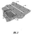
- valve metal anode means Adjacent the polymer mesh will be the valve metal anode means.
- a sheet of valve metal mesh shown generally at 2 lies adjacent to a resin mesh 50.
- the valve metal mesh 2 has individual diamond-shaped units. This shape is formed from strands 3 interconnecting at nodes 4. As shown in Fig. 2, the strands 3 and nodes 4 form a diamond aperture having a long way of design (LWD) in a horizontal direction. The short way of design (SWD) has in the opposite, vertical direction.
- LWD long way of design
- SWD short way of design
- void spacings are such as to halt or retard penetration of the valve metal mesh through the voids in the resin mesh, thus insuring desirable spacing between anode and cathode.
- the mesh structure is most typically formed as diamond-shaped apertures.
- the nodes 4 have double strand thickness. Usually individual strands have a thickness that does not exceed about 0.125 centimeter and a width across the strand which may be up to about 0.2 centimeter.
- Such “diamond-pattern” will feature apertures having a long way of design (LWD) from about 4, and preferably from about 6, centimeters up to about 9 centimeters, although a longer LWD is contemplated, and a short way of design (SWD) of from about 2, and preferably from about 2.5, up to about 4 centimeters.
- LWD long way of design
- SWD short way of design
- An SWD of less than about 2 centimeters, or an LWD of less than about 4 centimeters, in the preferred application. can be uneconomical in supplying an unneeded amount of metal for desirable cathodic protection.
- the metals of the valve metal mesh will most always be any of titanium, tantalum, zirconium and niobium. As well as the elemental metals themselves, the suitable metals of the mesh can include alloys of these metals with themselves and other metals as well as their intermetallic mixtures. Of particular interest for its ruggedness, corrosion resistance and availability is titanium. Where the mesh will be expanded from a metal sheet, the useful metal of the sheet will most always be an annealed metal. As representative of such serviceable annealed metals is Grade I titanium, an annealed titanium of low embrittlement.
- the metal mesh may then be prepared directly from the selected metal.
- the mesh be expanded from a sheet or coil of the valve metal.
- thin metal ribbons can be corrugated and individual cells, such as honeycomb shaped cells can be resistance welded together from the ribbons. Slitters or corrugating apparatus could be useful in preparing the metal ribbons and automatic resistance welding could be utilized to prepare the large void fraction mesh.
- a mesh of interconnected metal strands can directly result.
- a highly serviceable mesh will be prepared using such expansion technique with no broken strands being present.
- valve metal mesh can be directly prepared in large sheets of interconnected strands that are in a continuum of strands and nodes.
- the polymer mesh may also be in such form or, more typically it is prepared from strips which are subsequently bonded together at nodes.
- the interconnected metal strands will have a thickness dimension corresponding to the thickness of the initial planar sheet or coil. Usually this thickness will be within the range of from about 0.05 centimeter to about 0.125 centimeter. Use of a sheet having a thickness of less than about 0.05 centimeter, in an expansion operation, can not only lead to a deleterious number of broken strands, but also can produce a too flexible material that is difficult to handle. For economy, sheets of greater than about 0.125 centimeter are avoided. As a result of the expansion operation, the strands will interconnect at nodes providing a double strand thickness of the nodes.
- the node thickness will be within the range of from about 0.2 centimeter to about 0.25 centimeter. Referring to a sheet thickness of between about 0.05-0.125 centimeter, it can be expected that strands within such thickness range will have width dimensions of from about 0.05 centimeter to about 0.20 centimeter.
- the mesh can then be produced by expanding a sheet or coil of metal of appropriate thickness by an expansion factor of at least 10 times, a preferably at least 15 times.
- Useful mesh can also be prepared where a metal sheet has been expanded by a factor up to 30 times its original area. Even for an annealed value metal of elongation greater than 20 percent, an expansion factor of greater than 30:1 may lead to the preparation of mesh exhibiting strand breakage. On the other hand, an expansion factor of less than about 10:1 may leave additional metal without augmenting cathodic protection. Further in this regard, the resulting expanded mesh should have an at least 80 percent void fraction for efficiency and economy of cathodic protection.
- the expanded metal mesh will have a void fraction of at least about 90 percent, and may be as great as 92 to 96 percent or more, while still supplying sufficient metal and economical current distribution.
- the metal strands can be connected at a multiplicity of nodes providing a redundancy of current-carrying paths through the mesh which insures effective current distribution throughout the mesh even in the event of possible breakage of a number of individual strands, e.g., any breakage which might occur during installation or use.
- suitable redundancy for the metal strands will be provided in a network of strands most always interconnected by from about 500 to about 2000 nodes per square meter of the mesh. Greater than about 200 nodes per square meter of the mesh is uneconomical. On the other hand, less than about 500 of the interconnecting nodes per square meter of the mesh may provide for insufficient redundancy in the mesh.
- the resulting mesh can be readily rolled into coiled, or roll, configuration, such as for storage or transport or further operation.
- rolls having a hollow inner diameter of greater than 20 centimeters and an outer diameter of up to 150 centimeters, preferably 100 centimeters can be prepared. These rolls can be suitably coiled from the mesh when such is prepared in lengths within the range of from about 40 to about 200, and preferably up to 100 meters.
- the metal titanium such rolls will have weight on the order of from about 10-50 kilograms, but usually below 30 kilograms to be serviceable for handling, especially following coating, and particularly handling in the field during installation for cathodic protection.
- the valve metal mesh has been more particularly described in copending application Serial No. 855,550 the teachings of which are herein incorporated by reference.
- the expanded metal mesh can be usefully coated. It is to be understood that the mesh may also be coated before it is in mesh form, or combinations might be useful. Whether coated before or after being in mesh form, the substrate can be particularly useful for bearing a catalytic active material, thereby forming a catalytic structure. As an aspect of this use, the mesh substrate can have a catalyst coating, resulting in an anode structure. Usually before any of this, the valve metal mesh will be subjected to a cleaning operation, e.g., a degreasing operation, which can include cleaning plus etching, as is well known in the art of preparing a valve metal to receive an electrochemically active coating.
- a cleaning operation e.g., a degreasing operation, which can include cleaning plus etching, as is well known in the art of preparing a valve metal to receive an electrochemically active coating.
- valve metal which may also be referred to herein as a "film-forming" metal, will not function as an anode without an electrochemically active coating which prevents passivation of the valve metal surface.
- This electrochemically active coating may be provided from platinum or other platinum group metal, or it may be any of a number of active oxide coatings such as the platinum group metal oxides, magnetite, ferrite, cobalt spinel, or mixed metal oxide coatings, which have been developed for use as anode coatings in the industrial electrochemical industry. It is particularly preferred for extended life protection of concrete structures that the anode coating be a mixed metal oxide, which can be a solid solution of a film-forming metal oxide and platinum group metal or platinum group metal oxide.
- the mixed metal oxide coating is highly catalytic for the oxygen evolution reaction, and in a chloride contaminated concrete environment, will evolve no chlorine or hypochlorite.
- the platinum group metal or mixed metal oxides for the coating are such as have been generally described in or more of U.S. Patents 3,265,526, 3,632,498, 3,711,385 and 4,528,084. More particularly, such platinum group metals include platinum, palladium, rhodium, iridium and ruthenium or alloys of themselves and with other metals.
- Mixed metal oxides include at least one of the oxides of these platinum group metals in combination with at least one oxide of a valve metal or another non-precious metal. It is preferred for economy that the coating be such as have been disclosed in the U.S. Patent No. 4,528,084.
- the metal mesh will be connected to current supply means including a current distribution member, usually an elongate member such as a metal strip laid down on top of the valve metal mesh, or under the valve metal mesh, i.e., between the polymer mesh and the valve metal mesh, or distributor members can be positioned both over and under the valve metal mesh.
- a current distribution member usually an elongate member such as a metal strip laid down on top of the valve metal mesh, or under the valve metal mesh, i.e., between the polymer mesh and the valve metal mesh, or distributor members can be positioned both over and under the valve metal mesh.
- Such member will most always be a valve metal and preferably is the same metal alloy or intermetallic mixture as the metal most predominantly found in the expanded valve metal mesh.
- the current distribution member must be firmly affixed to the metal mesh. Such a manner of firmly fixing the member to the mesh can be by welding.
- the member in strip form can be welded to the mesh at every node and thereby provide uniform distribution of current thereto.
- Such a member positioned along a piece of mesh about every 10 to 50 meters will usually be sufficient to serve as a current distributor for such piece.
- Such current distributor member can then connect outside of the concrete environment to a current conductor for supplying an impressed current, e.g., at a current density of up to 200 mA/m2 of the valve metal mesh strand surface area.
- a roll (not shown) of the polymer mesh can be unrolled onto the surface 40 of such deck or substructure.
- a roll 32 of the greatly expanded valve metal mesh with a suitable electrochemically active coating sometimes referred to hereinafter simply as the "anode" is applied.
- This provides unrolled valve metal mesh 30 over the unrolled polymer mesh 50.
- the single roll is simply unrolled, making sure that the polymer mesh is applied against the concrete.
- means of fixing mesh to substructure can be any of those useful for binding polymer mesh and a metal mesh to concrete that will not deleteriously disrupt the anodic nature of the mesh.
- non-conductive retaining members will be useful with each mesh; and, each mesh can be fastened separately. Or both meshes may be fastened at the same time, particularly when they are supplied as a single roll.
- Such retaining members for economy are advantageously plastic and in a form such as pegs or studs.
- plastics such a polyvinyl halides or polyolefins can be useful. These plastic retaining members can be inserted into holes 31 drilled into the concrete surface (40).
- Such retainers may have an enlarged head engaging a strand of the mesh under the head to hold the anode in place, or the retainers may be partially slotted to grip a strand of the mesh located directly over the hole drilled into the concrete.
- Current distributor members e.g., metal strips, are applied over the valve metal mesh or between it and the polymer mesh, or both, and fixed to the valve metal mesh as by welding.
- an ionically conductive overlay will be employed to completely cover such resulting mesh structure.
- Such overlay will further enhance firmly fixing the anode in place over the concrete substructure.
- Serviceable ionically conductive overlays include portland cement and polymer-modified concrete. Before application of the overlay, it may be serviceable to apply a cement-based bonding grout to the resulting mesh structure.
- the resulting mesh structure can be overlaid with from about 2 to about 6 centimeters of a portland cement or a latex modified concrete.
- the mesh structure may be generally covered by from about 0.8 to about 2 centimeters of polymer modified concrete.
- the resulting mesh structure provides the additional advantage of acting as a reinforcing means, thereby improving the mechanical properties and useful life of the overlay.
- the described preferred embodiments employ coated valve metal meshes, it is also possible to support an anode made of coated valve metal wires or ribbons on the polymer mesh.
- the polymer mesh may be a perforated sheet having smaller openings than the described polymer meshes.
- the wires or ribbons may be disposed transversally or longitudinally of the polymer mesh, or arrranged in criss-cross fashion. Current feeders are welded to these wires or ribbons at suitable intervals.
- the valve metal ribbons may be coated on their underside or on both faces with an electrochemically active coating.
- the valve metal wires or ribbons may be attached to the polymer mesh, eg. by heat bonding. When the mesh is in rolled configuration, these wires or ribbons will be inside, so that when the mesh is unrolled onto a surface, the polymer spaces the valve metal wires or ribbons from this surface.
Landscapes
- Chemical & Material Sciences (AREA)
- Engineering & Computer Science (AREA)
- Materials Engineering (AREA)
- Mechanical Engineering (AREA)
- Metallurgy (AREA)
- Organic Chemistry (AREA)
- Prevention Of Electric Corrosion (AREA)
Applications Claiming Priority (2)
| Application Number | Priority Date | Filing Date | Title |
|---|---|---|---|
| US37672089A | 1989-07-07 | 1989-07-07 | |
| US376720 | 1989-07-07 |
Publications (1)
| Publication Number | Publication Date |
|---|---|
| EP0407348A1 true EP0407348A1 (fr) | 1991-01-09 |
Family
ID=23486191
Family Applications (1)
| Application Number | Title | Priority Date | Filing Date |
|---|---|---|---|
| EP90810491A Withdrawn EP0407348A1 (fr) | 1989-07-07 | 1990-06-28 | Anode et séparateur en forme de grille employés dans le béton armé |
Country Status (5)
| Country | Link |
|---|---|
| EP (1) | EP0407348A1 (fr) |
| JP (1) | JP2886284B2 (fr) |
| AU (1) | AU5867790A (fr) |
| CA (1) | CA2018869A1 (fr) |
| NO (1) | NO903042L (fr) |
Cited By (10)
| Publication number | Priority date | Publication date | Assignee | Title |
|---|---|---|---|---|
| EP0560452A1 (fr) * | 1992-03-13 | 1993-09-15 | ITALCEMENTI S.p.A. | Matériau support de type cimentaire pour la protection cathodique de constructions en béton armé |
| EP0581433A1 (fr) * | 1992-07-21 | 1994-02-02 | Zeneca Inc. | Système de protection cathodique comprenant un revêtement électro-conducteur et composition de revêtement pour celui-ci |
| EP0668373A1 (fr) * | 1992-06-03 | 1995-08-23 | Eltech Systems Corporation | Méthode et dispositif pour la protection cathodique de structures en béton armé |
| EP0669299A3 (fr) * | 1994-02-15 | 1995-11-08 | Eltech Systems Corp | Structure de beton armé. |
| US5609748A (en) * | 1988-08-09 | 1997-03-11 | Heraeus Elektroden Gmbh | Anode for cathodic protection against corrosion |
| WO2002002875A1 (fr) * | 2000-07-05 | 2002-01-10 | Newcastle University Ventures Limited | Structure geosynthetique |
| WO2009127530A3 (fr) * | 2008-04-18 | 2010-03-18 | Industrie De Nora S.P.A. | Anode pour protection cathodique |
| ITMI20101689A1 (it) * | 2010-09-17 | 2012-03-18 | Industrie De Nora Spa | Anodo per protezione catodica e metodo per il suo ottenimento |
| EP2431496A1 (fr) * | 2010-09-17 | 2012-03-21 | Soletanche Freyssinet | Anode composite pour système de protection cathodique |
| US10808326B2 (en) | 2018-02-23 | 2020-10-20 | De Nora Tech, Llc | Anode support device for cathodic protection of metal reinforcement |
Families Citing this family (5)
| Publication number | Priority date | Publication date | Assignee | Title |
|---|---|---|---|---|
| US5062934A (en) * | 1989-12-18 | 1991-11-05 | Oronzio Denora S.A. | Method and apparatus for cathodic protection |
| CA2075780C (fr) * | 1991-09-23 | 2002-07-30 | Michele Tettamanti | Anode pour systeme de protection cathodique d'un beton arme; mode d'emploi |
| AU7138200A (en) | 1999-07-22 | 2001-02-13 | Infrastructure Repair Technologies, Inc. | Method of treating corrosion in reinforced concrete structures by providing a uniform surface potential |
| JP2007039996A (ja) * | 2005-08-03 | 2007-02-15 | Nippon Steel Composite Co Ltd | コンクリート構造物の補強及び防食方法、並びに、補強・防食材 |
| ITMI20051738A1 (it) * | 2005-09-20 | 2007-03-21 | De Nora Elettrodi S P A | Anodo discreto per la protezione catodica del calcestruzzo armato |
Citations (1)
| Publication number | Priority date | Publication date | Assignee | Title |
|---|---|---|---|---|
| WO1986006759A1 (fr) * | 1985-05-07 | 1986-11-20 | Eltech Systems Corporation | Systeme de protection cathodique pour une structure en beton arme et procede d'installation |
-
1990
- 1990-06-13 CA CA002018869A patent/CA2018869A1/fr not_active Abandoned
- 1990-06-28 EP EP90810491A patent/EP0407348A1/fr not_active Withdrawn
- 1990-07-04 AU AU58677/90A patent/AU5867790A/en not_active Abandoned
- 1990-07-06 JP JP2179412A patent/JP2886284B2/ja not_active Expired - Lifetime
- 1990-07-06 NO NO90903042A patent/NO903042L/no unknown
Patent Citations (1)
| Publication number | Priority date | Publication date | Assignee | Title |
|---|---|---|---|---|
| WO1986006759A1 (fr) * | 1985-05-07 | 1986-11-20 | Eltech Systems Corporation | Systeme de protection cathodique pour une structure en beton arme et procede d'installation |
Non-Patent Citations (1)
| Title |
|---|
| CONSTRUCTION REPAIR, vol. 3, no. 5, June 1989, pages 34-38, London, GB; R.A. GUMMOW: "Selection and performance evaluation of cathodic protection systems for reinforced-concrete parking structures" * |
Cited By (18)
| Publication number | Priority date | Publication date | Assignee | Title |
|---|---|---|---|---|
| US5609748A (en) * | 1988-08-09 | 1997-03-11 | Heraeus Elektroden Gmbh | Anode for cathodic protection against corrosion |
| EP0560452A1 (fr) * | 1992-03-13 | 1993-09-15 | ITALCEMENTI S.p.A. | Matériau support de type cimentaire pour la protection cathodique de constructions en béton armé |
| EP0668373A1 (fr) * | 1992-06-03 | 1995-08-23 | Eltech Systems Corporation | Méthode et dispositif pour la protection cathodique de structures en béton armé |
| EP0581433A1 (fr) * | 1992-07-21 | 1994-02-02 | Zeneca Inc. | Système de protection cathodique comprenant un revêtement électro-conducteur et composition de revêtement pour celui-ci |
| US5364511A (en) * | 1992-07-21 | 1994-11-15 | Zeneca Limited | Cathodic protection system and a coating and coating composition therefor |
| US5431795A (en) * | 1992-07-21 | 1995-07-11 | Thoro Systems Products Inc. | Cathodic protection system and a coating and coating composition therefor |
| EP0669299A3 (fr) * | 1994-02-15 | 1995-11-08 | Eltech Systems Corp | Structure de beton armé. |
| WO2002002875A1 (fr) * | 2000-07-05 | 2002-01-10 | Newcastle University Ventures Limited | Structure geosynthetique |
| WO2009127530A3 (fr) * | 2008-04-18 | 2010-03-18 | Industrie De Nora S.P.A. | Anode pour protection cathodique |
| KR20110005877A (ko) * | 2008-04-18 | 2011-01-19 | 인두스트리에 데 노라 에스.피.에이. | 음극 부식방지용 양극 |
| CN102007229B (zh) * | 2008-04-18 | 2012-08-22 | 德诺拉工业有限公司 | 阴极防护用阳极 |
| US9194047B2 (en) | 2008-04-18 | 2015-11-24 | Industrie De Nora S.P.A. | Anode for cathodic protection |
| ITMI20101689A1 (it) * | 2010-09-17 | 2012-03-18 | Industrie De Nora Spa | Anodo per protezione catodica e metodo per il suo ottenimento |
| EP2431496A1 (fr) * | 2010-09-17 | 2012-03-21 | Soletanche Freyssinet | Anode composite pour système de protection cathodique |
| WO2012035107A1 (fr) * | 2010-09-17 | 2012-03-22 | Industrie De Nora S.P.A. | Anode de protection cathodique et son procédé de fabrication |
| WO2012035167A3 (fr) * | 2010-09-17 | 2012-07-05 | Soletanche Freyssinet | Anode composite pour système de protection cathodique |
| EA024024B1 (ru) * | 2010-09-17 | 2016-08-31 | Индустрие Де Нора С.П.А. | Способ изготовления анода для катодной защиты |
| US10808326B2 (en) | 2018-02-23 | 2020-10-20 | De Nora Tech, Llc | Anode support device for cathodic protection of metal reinforcement |
Also Published As
| Publication number | Publication date |
|---|---|
| NO903042D0 (no) | 1990-07-06 |
| NO903042L (no) | 1991-01-08 |
| CA2018869A1 (fr) | 1991-01-07 |
| AU5867790A (en) | 1991-01-10 |
| JPH0353086A (ja) | 1991-03-07 |
| JP2886284B2 (ja) | 1999-04-26 |
Similar Documents
| Publication | Publication Date | Title |
|---|---|---|
| US4900410A (en) | Method of installing a cathodic protection system for a steel-reinforced concrete structure | |
| US5759361A (en) | Cathodic protection system for a steel-reinforced concrete structure | |
| EP0407348A1 (fr) | Anode et séparateur en forme de grille employés dans le béton armé | |
| EP0222829B2 (fr) | Systeme de protection cathodique pour une structure en beton arme et procede d'installation | |
| EP0623691B1 (fr) | Anode de protection cathodique et systèmes | |
| US5451307A (en) | Expanded metal mesh and anode structure | |
| AU638094B2 (en) | Novel electrodes and cathodic protection system | |
| EP0534392B1 (fr) | Anode pour la protection cathodique de béton armé et sa méthode d'utilisation | |
| US5098543A (en) | Cathodic protection system for a steel-reinforced concrete structure | |
| US6562229B1 (en) | Louvered anode for cathodic protection systems | |
| US5423961A (en) | Cathodic protection system for a steel-reinforced concrete structure | |
| EP0292428B1 (fr) | Système à anode en forme de ruban pour protection cathodique de béton armé d'acier | |
| CA2302966C (fr) | Anode en echelle pour protection cathodique | |
| CA2195613C (fr) | Anode en echelle pour protection cathodique de l'armature metallique du beton expose aux agents atmospheriques | |
| US5104502A (en) | Cathodic protection system and its preparation | |
| US5200259A (en) | Fiber-filled concrete overlay in cathodic protection | |
| HK86390A (en) | Cathodic protection system for a steel-reinforced concrete structure and method of installation | |
| CA1332374C (fr) | Treillis en metal deploye et enduit de protection cathodique | |
| NO169299B (no) | Opprullet ventilmetallnetting og anvendelse av denne som anode i utrullet tilstand |
Legal Events
| Date | Code | Title | Description |
|---|---|---|---|
| PUAI | Public reference made under article 153(3) epc to a published international application that has entered the european phase |
Free format text: ORIGINAL CODE: 0009012 |
|
| AK | Designated contracting states |
Kind code of ref document: A1 Designated state(s): AT BE CH DE DK ES FR GB GR IT LI LU NL SE |
|
| 17P | Request for examination filed |
Effective date: 19901220 |
|
| STAA | Information on the status of an ep patent application or granted ep patent |
Free format text: STATUS: THE APPLICATION HAS BEEN WITHDRAWN |
|
| 18W | Application withdrawn |
Withdrawal date: 19930127 |