EP2431496A1 - Anode composite pour système de protection cathodique - Google Patents
Anode composite pour système de protection cathodique Download PDFInfo
- Publication number
- EP2431496A1 EP2431496A1 EP10305998A EP10305998A EP2431496A1 EP 2431496 A1 EP2431496 A1 EP 2431496A1 EP 10305998 A EP10305998 A EP 10305998A EP 10305998 A EP10305998 A EP 10305998A EP 2431496 A1 EP2431496 A1 EP 2431496A1
- Authority
- EP
- European Patent Office
- Prior art keywords
- anode member
- cathodic protection
- spacer element
- protection device
- metallic reinforcement
- Prior art date
- Legal status (The legal status is an assumption and is not a legal conclusion. Google has not performed a legal analysis and makes no representation as to the accuracy of the status listed.)
- Withdrawn
Links
Images

Classifications
-
- C—CHEMISTRY; METALLURGY
- C23—COATING METALLIC MATERIAL; COATING MATERIAL WITH METALLIC MATERIAL; CHEMICAL SURFACE TREATMENT; DIFFUSION TREATMENT OF METALLIC MATERIAL; COATING BY VACUUM EVAPORATION, BY SPUTTERING, BY ION IMPLANTATION OR BY CHEMICAL VAPOUR DEPOSITION, IN GENERAL; INHIBITING CORROSION OF METALLIC MATERIAL OR INCRUSTATION IN GENERAL
- C23F—NON-MECHANICAL REMOVAL OF METALLIC MATERIAL FROM SURFACE; INHIBITING CORROSION OF METALLIC MATERIAL OR INCRUSTATION IN GENERAL; MULTI-STEP PROCESSES FOR SURFACE TREATMENT OF METALLIC MATERIAL INVOLVING AT LEAST ONE PROCESS PROVIDED FOR IN CLASS C23 AND AT LEAST ONE PROCESS COVERED BY SUBCLASS C21D OR C22F OR CLASS C25
- C23F13/00—Inhibiting corrosion of metals by anodic or cathodic protection
- C23F13/02—Inhibiting corrosion of metals by anodic or cathodic protection cathodic; Selection of conditions, parameters or procedures for cathodic protection, e.g. of electrical conditions
- C23F13/06—Constructional parts, or assemblies of cathodic-protection apparatus
- C23F13/08—Electrodes specially adapted for inhibiting corrosion by cathodic protection; Manufacture thereof; Conducting electric current thereto
- C23F13/18—Means for supporting electrodes
-
- C—CHEMISTRY; METALLURGY
- C23—COATING METALLIC MATERIAL; COATING MATERIAL WITH METALLIC MATERIAL; CHEMICAL SURFACE TREATMENT; DIFFUSION TREATMENT OF METALLIC MATERIAL; COATING BY VACUUM EVAPORATION, BY SPUTTERING, BY ION IMPLANTATION OR BY CHEMICAL VAPOUR DEPOSITION, IN GENERAL; INHIBITING CORROSION OF METALLIC MATERIAL OR INCRUSTATION IN GENERAL
- C23F—NON-MECHANICAL REMOVAL OF METALLIC MATERIAL FROM SURFACE; INHIBITING CORROSION OF METALLIC MATERIAL OR INCRUSTATION IN GENERAL; MULTI-STEP PROCESSES FOR SURFACE TREATMENT OF METALLIC MATERIAL INVOLVING AT LEAST ONE PROCESS PROVIDED FOR IN CLASS C23 AND AT LEAST ONE PROCESS COVERED BY SUBCLASS C21D OR C22F OR CLASS C25
- C23F13/00—Inhibiting corrosion of metals by anodic or cathodic protection
- C23F13/02—Inhibiting corrosion of metals by anodic or cathodic protection cathodic; Selection of conditions, parameters or procedures for cathodic protection, e.g. of electrical conditions
- C23F13/06—Constructional parts, or assemblies of cathodic-protection apparatus
- C23F13/08—Electrodes specially adapted for inhibiting corrosion by cathodic protection; Manufacture thereof; Conducting electric current thereto
- C23F13/10—Electrodes characterised by the structure
-
- C—CHEMISTRY; METALLURGY
- C23—COATING METALLIC MATERIAL; COATING MATERIAL WITH METALLIC MATERIAL; CHEMICAL SURFACE TREATMENT; DIFFUSION TREATMENT OF METALLIC MATERIAL; COATING BY VACUUM EVAPORATION, BY SPUTTERING, BY ION IMPLANTATION OR BY CHEMICAL VAPOUR DEPOSITION, IN GENERAL; INHIBITING CORROSION OF METALLIC MATERIAL OR INCRUSTATION IN GENERAL
- C23F—NON-MECHANICAL REMOVAL OF METALLIC MATERIAL FROM SURFACE; INHIBITING CORROSION OF METALLIC MATERIAL OR INCRUSTATION IN GENERAL; MULTI-STEP PROCESSES FOR SURFACE TREATMENT OF METALLIC MATERIAL INVOLVING AT LEAST ONE PROCESS PROVIDED FOR IN CLASS C23 AND AT LEAST ONE PROCESS COVERED BY SUBCLASS C21D OR C22F OR CLASS C25
- C23F2201/00—Type of materials to be protected by cathodic protection
- C23F2201/02—Concrete, e.g. reinforced
Definitions
- the present invention relates to the field of cathodic protection of reinforced structures.
- Metallic components are used to reinforce structures in many applications.
- Reinforced concrete is a typical application, in which steel bars are embedded into concrete in order to combine the compressive strength of concrete and the tensile strength of steel.
- the cathodic protection system described below can be used to protect from corrosion steel bars of reinforced concrete or other kinds of metallic reinforcements, for example, cables or bars used in tie rod applications.
- a cathodic protection system can be referred to as a cathodic prevention system if it is incorporated into the structure at the time of construction, which is the situation addressed by the present invention.
- an anode In an impressed current cathodic protection system, an anode is embedded within the concrete to distribute current to the metallic elements to be protected.
- any short-circuit between the cathode and the anode member prevents current flow and causes malfunction of the cathodic protection system.
- the metallic elements to be protected are usually in the form of a rebar cage and an array of anode members, such as titanium ribbons, are distributed in the concrete, particularly in the concrete cover between the rebar cage and the surface of the concrete structure.
- the concrete cover is often relatively thin, resulting that the anode members can be close to the reinforcement (e.g. within 30 mm).
- Small discrete plastic clips fixed to the rebar cage are used to hold the anode members a certain distance from the rebar cage.
- such clips lack robustness. Flexibility of the anode member may cause it to touch the rebar cage between adjacent clips. Also, the clips cannot maintain the anode strongly enough when concrete is vibrated after pouring.
- the present document addresses the need to safely hold an anode member of a cathodic protection system in the vicinity of, but separated from the metallic element to be protected.
- a cathodic protection device for a structure including metallic reinforcement comprises an electrically conducting anode member extending along a longitudinal direction and a spacer element having an electrical conductivity lower than the anode member.
- the spacer element extends along the longitudinal direction to support the anode member, and is arranged to hold the anode member apart from the metallic reinforcement of the structure.
- the spacer element has a primary function of preventing electrical contact between the anode and the reinforcement located in the vicinity of the device. By stiffening the device, it avoids undesired contacts due to bending of the anode when the device is handled, when the filler material, for example concrete or hardened mortar or cement grout is poured, vibrated, etc. The stiffening also facilitates and speeds up the installation. Furthermore, the spacer element restricts other objects (for example tie wires) to come into contact with the anode. It is preferentially designed to permit the current flow between the anode and the reinforcement to be protected.
- the spacer element may be in the form of a plastic profile having apertures to permit current flow in material between the anode member and the metallic reinforcement.
- plastic profile may have U-shaped, H-shaped, T-shaped or cylindrical cross-section.
- the spacer element may be in the form of a matrix cast around the anode member, the matrix having an electrical conductivity of the same order as a material in which at least part of the metallic reinforcement and the cathodic protection device are embedded.
- the spacer element may comprise a cement material, with or without fibres, surrounding the anode member.
- Another includes a screw-shaped spacer element, and an anode member in the form of a wire, ribbon or strip helically wound into the thread of the screw-shaped spacer element.
- Another aspect of the invention relates to a reinforced structure, comprising metallic reinforcement, at least one cathodic protection device as defined above, structural material in which at least part of the metallic reinforcement and the cathodic protection device are embedded, and a DC power source having terminals electrically connected to the metallic reinforcement and to the anode member of the cathodic protection device.
- Electrically insulating ties may be provided for fixing the cathodic protection device to a metallic reinforcement.
- At least one electrical conductor may be used for connecting a terminal of the DC power source to the anode member of the cathodic protection device, and an insulating cover is mounted around an intersection area where the electrical conductor is secured in electrical contact with the anode member.
- the electrical conductor has an insulating coating interrupted in the intersection area, wherein the spacer element of the cathodic protection device is interrupted in the intersection area.
- the insulating cover is arranged to prevent contact of the anode member or the electrical conductor with the metallic reinforcement.
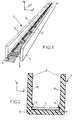
- Figure 1 is a perspective view of an embodiment of a cathodic protection device.
- Figure 2 illustrates a cross section of another embodiment of a cathodic protection device.
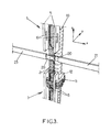
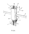
- Figures 3 and 4 are perspective views of a cathodic protection device mounted on a rebar cage of a reinforced concrete structure, at different stages of the assembly.
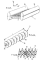
- Figure 5 is a perspective view of another embodiment of a cathodic protection device.
- Figure 6A is a perspective view of another embodiment of a cathodic protection device.
- Figure 6B is an axial sectional view of an assembly of two cathodic protection devices as shown in figure 6A .
- Figure 7A is a perspective view of yet another embodiment of a cathodic protection device.
- Figure 7B is a cross-sectional view of the cathodic protection device of figure 7A , along plane A-A.
- Figures 1, 2 and 3 show three embodiments of a cathodic protection device 1 according to the invention, including a spacer element 3 and an electrically conductive anode member 2.
- the spacer element 3 is in the form of a plastic profile extending along a longitudinal direction y.
- the anode member 2 is typically in the form of a flat ribbon of expanded metal, for example made of coated titanium. However it may also be non-expanded, corrugated, cylindrical or other shape.
- the illustrated cathodic protection device 1 is prefabricated. It can be manufactured remote from construction sites.
- the plastic profile 3 which has a stiffening function is made of an electrically insulating material, e.g. high density polyethylene (HDPE), crosslinked polyethylene (XLPE), polypropylene (PP), polyvinyl chloride (PVC) or recycled or reconstituted plastic. It has a central part 4 for holding the anode member 2 along the direction y and a transverse direction x, and two wing parts 5 perpendicular to the direction x on both sides of the central part 4 to rigidify the device 1.
- the cross-section of the spacer member 3 is H-shaped, while it is U-shaped in the embodiments of figures 2 and 3 .
- the central part 4 and/or the wing parts of the plastic profile have apertures 6 whose function is to let an ionic current flow between the anode member 3 and a cathode located nearby, while keeping a sufficient rigidity of the device 1.
- the above-mentioned ionic current flows in a filler material in which both the cathode and the protection device 1 are embedded, for example concrete or hardened mortar or cement grout.
- the rigidity of the device is considered sufficient if the spacer element 3 keeps the anode member 2 safely separated from the cathode when the device is installed and when the filler material is injected and/or vibrated to embed the cathode and the device.
- the apertures 6 are also useful to let the filler material encapsulate the anode member 2 when it is injected.
- the apertures 6 are formed in the central part 4 of the H-shaped plastic profile 3.
- the apertures 6 are formed both in the central part 4 and in the wing parts 5 of the U-shaped plastic profile 3.
- the length of the apertures 6 provided in the central part 4 and the intervals between them along the longitudinal direction y are selected to achieve the above function of letting current flow while ensuring rigidity of the device.
- the anode member 2 can be fixed to the spacer element 3 by welding on the bridges 7 located between the apertures 6 on the central part 4 of the plastic profile 3.
- the metallic ribbon 2 is heated above the melting point of the plastic material and pressed onto the central part 4 of the profile, thus melting the plastic at the bridges 7 and welding the ribbon in place.
- Figure 2 illustrates an alternative way of fixing the anode member 2 to the spacer element 3 using a snap fit assembly.
- the ribbon forming the anode member 2 has a width (along direction x) slightly smaller than the gap between the inner faces 8 of the wing parts 5 of the plastic profile.
- Each of these inner faces 8 has a projection 9 near the central part 4 such that the anode member 2 can be held between the central part 4 and the projections 9.
- the shape of the projections 9 is defined when extruding the plastic profile 3.
- the anode member is forced into place using the elasticity of the expanded metal and/or by pulling apart the two wing parts 5.
- Figures 3 and 4 show, in their bottom part, one way of fixing the protection device 1 to a reinforcement consisting of a steel bar 10 of a reinforced concrete structure, before pouring the concrete material.
- insulating ties consisting of plastic collars 11 are inserted in the apertures 6 provided in the wing parts 5 of the spacer element 3, looped around the steel bar 10 and tightened.
- a plastic pad 12 may be inserted between the spacer element 2 and the steel bar at the position of each plastic collar 11 if it is needed to have a desired distance between the anode and the cathode.
- the rigidity of the spacer element 3 eliminates the risks of contact between anode and cathode. It will be appreciated that many different ways can be used alternatively to hold the cathodic protection device 1 in position before pouring the concrete material.
- a DC power source (not shown) has a positive terminal connected to the anode member 2 and a negative terminal connected to the metallic reinforcement to be protected from corrosion.
- a reinforced concrete structure usually has a network of metallic reinforcement.
- cathode protection devices 1 will be distributed in the volume to be constructed with concrete so as to efficiently protect the reinforcement.
- the spatial distribution of the anodes is determined by conventional methods.
- the cathodic protection device 1 avoids contacts between the anodes and the cathodes even when the concrete is poured and vibrated to homogenize the reinforced concrete.
- electrical conductors 20 for connecting the anode member(s) 2 to the positive terminal of the DC power source, electrical conductors 20 of the type shown in figures 3 and 4 can be used. These conductors 20 consist of metallic strips having an insulating coating in the form of a plastic sheath 21 to isolate them electrically from the filler material. In the illustrated embodiment, the strips 20 extend transversely to the anode members 2 of adjacent cathodic protection devices, and in the intersection area, their plastic sheath is removed to permit electrical contact with the anode members 2. One or two metallic strips 20 and one or two anode members 2 are overlapped in the intersection area and secured together in electrical contact by welding and/or other methods. The spacer element 3 of each device 1 is also interrupted in the intersection area so as to facilitate the assembly of the metallic components.
- a metallic reinforcement 10 may be located in the vicinity of the intersection area where the metallic strips 20 and anode members 2 are exposed.
- an insulating cover 25 as shown in figure 4 can be used.
- the cover 25 surrounds the intersection area so as to protect the metallic strips 20 and the anode members 2 in the intersection area where the plastic sheath 21 and the spacer element 3 are absent, such that the strips 20 and anode members 2 are prevented from contacting the reinforcement 10.
- the cover 25 may include a plastic plate 26 to be installed between the device 1 and the rebar cage 10 and a U-shaped profile 27 whose internal cross-section matches the external cross-section of the spacer elements 3.
- the lateral parts of the U-shaped profile 27 have notches 28 to leave a passage for the strips 20 and their sheaths 21 on both sides of the intersection area.
- the U-shaped profile 27 can then be engaged with the two ends of the spacer elements 3 and attached to the plate 26 by means of clips (not shown) provided at the ends of the lateral parts of the U-shaped profile 27.
- Figure 5 illustrates an alternative embodiment of the cathodic protection device 1, in which the plastic profile 3 has two lateral parts 3A, 3B directly extruded on the metallic ribbon forming the anode member 2 by means of a suitably shaped extrusion die. If it is necessary to further stiffen the device, bridge elements 30 can be welded to the lateral parts 3A, 3B so as to maintain the distance between them.
- the spacer element 3 has the shape of a screw made of plastic or another insulating material.
- a wire, ribbon or strip forming the anode member 2 (shown in figure 6B but not in figure 6A ) is helically wound at the bottom of the thread 34 of the screw-shaped spacer element 3.
- the helical rib 35 of the spacer element 3 has a sufficient height to accommodate the wire 2 and to maintain a minimum distance between the wire and the periphery of the screw-shaped spacer element 3, in order to safely avoid contact of the wire with a reinforcement or other metallic part which may come close to or against the screw-shaped spacer element 3.
- Such spacer element 3 has a length L of about one meter for instance. It can be assembled end-to-end with another similar spacer element prior to winding the anode member 2. For this, one end of the spacer element has an axial plug 36 and the other end has a recess 37 for receiving the plug 36 of a similar spacer element 3 assembled next to it as shown in figure 6B .
- the winding of the wire 2 onto a plurality of screw-shaped spacer elements 3 dimensioned and assembled end-to-end according to the needs can be performed on the construction site.
- the diameter of the wire 2 may be of about 2 millimeters, for example.
- the spacer element 3 is made of an electrically insulating material. It has an open structure (e.g. U-shaped or H-shaped profile, apertures 6, thread 34) in order to prevent shielding between the anode members 2 and the metallic reinforcement 10 to be protected.
- open structure e.g. U-shaped or H-shaped profile, apertures 6, thread 34
- the spacer element may be made of a material having some electrical conductivity, for example an electrical conductivity of the same order of magnitude as the filler material (e.g. concrete) in which the reinforcement is embedded.
- the filler material e.g. concrete
- the spacer element 3 can be in the form of a cylindrical matrix cast around a wire-shaped anode member 2.
- a convenient material for forming the matrix is hardened cement grout, possibly incorporating some fibres.
- the spacer member 3 is then formed in a cylindrical mold in which the wire, ribbon or strip is centrally located to be surrounded by the grout.
- a cathodic protection device 1 is obtained which is suitable for embedding into concrete or another structural material.
- its length L' is about 3 meters and its diameter D about 25 millimeters.
- the anode member 2 may be a rigid wire having a diameter d of about 4 millimeters.
- a flexible connection wire 40 may be soldered at the end of the rigid wire (or one at both ends).
- the connection wire 40 has an insulating coating and extends beyond the cement matrix 3 for connection to the DC power supply.
- FIG. 7A-B An embodiment as illustrated in figure 7A-B can be applied to reinforced concrete, and it may also be useful in other applications including tie rod arrangements where it can be used to protect anchored strands or rods from corrosion.
Landscapes
- Chemical & Material Sciences (AREA)
- Engineering & Computer Science (AREA)
- Materials Engineering (AREA)
- Mechanical Engineering (AREA)
- Metallurgy (AREA)
- Organic Chemistry (AREA)
- Prevention Of Electric Corrosion (AREA)
Priority Applications (2)
| Application Number | Priority Date | Filing Date | Title |
|---|---|---|---|
| EP10305998A EP2431496A1 (fr) | 2010-09-17 | 2010-09-17 | Anode composite pour système de protection cathodique |
| PCT/EP2011/066240 WO2012035167A2 (fr) | 2010-09-17 | 2011-09-19 | Anode composite pour système de protection cathodique |
Applications Claiming Priority (1)
| Application Number | Priority Date | Filing Date | Title |
|---|---|---|---|
| EP10305998A EP2431496A1 (fr) | 2010-09-17 | 2010-09-17 | Anode composite pour système de protection cathodique |
Publications (1)
| Publication Number | Publication Date |
|---|---|
| EP2431496A1 true EP2431496A1 (fr) | 2012-03-21 |
Family
ID=43587220
Family Applications (1)
| Application Number | Title | Priority Date | Filing Date |
|---|---|---|---|
| EP10305998A Withdrawn EP2431496A1 (fr) | 2010-09-17 | 2010-09-17 | Anode composite pour système de protection cathodique |
Country Status (2)
| Country | Link |
|---|---|
| EP (1) | EP2431496A1 (fr) |
| WO (1) | WO2012035167A2 (fr) |
Cited By (1)
| Publication number | Priority date | Publication date | Assignee | Title |
|---|---|---|---|---|
| EP2868774A3 (fr) * | 2013-11-05 | 2015-11-11 | Magontec GmbH | Accessoire pour un dispositif destiné à la protection cathodique contre la corrosion |
Families Citing this family (1)
| Publication number | Priority date | Publication date | Assignee | Title |
|---|---|---|---|---|
| US10808326B2 (en) * | 2018-02-23 | 2020-10-20 | De Nora Tech, Llc | Anode support device for cathodic protection of metal reinforcement |
Citations (7)
| Publication number | Priority date | Publication date | Assignee | Title |
|---|---|---|---|---|
| DE1546006A1 (de) * | 1964-06-09 | 1969-06-19 | Karl Schmidt | Verfahren und Vorrichtung fuer kathodischen Schutz in wasserfuehrenden Aggregaten,insbesondere Verbrennungsmaschinen |
| US4434039A (en) * | 1982-12-17 | 1984-02-28 | Texas Instruments Incorporated | Corrosion protection system for hot water tanks |
| EP0407348A1 (fr) * | 1989-07-07 | 1991-01-09 | Eltech Systems Corporation | Anode et séparateur en forme de grille employés dans le béton armé |
| EP0534392A1 (fr) * | 1991-09-23 | 1993-03-31 | Oronzio De Nora S.A. | Anode pour la protection cathodique de béton armé et sa méthode d'utilisation |
| US5531873A (en) * | 1990-06-20 | 1996-07-02 | Savcor-Consulting Oy | Electrode arrangement to be used in the cathodic protection of concrete structures and a fixing element |
| US5609748A (en) * | 1988-08-09 | 1997-03-11 | Heraeus Elektroden Gmbh | Anode for cathodic protection against corrosion |
| WO2009127530A2 (fr) * | 2008-04-18 | 2009-10-22 | Industrie De Nora S.P.A. | Anode pour protection cathodique |
-
2010
- 2010-09-17 EP EP10305998A patent/EP2431496A1/fr not_active Withdrawn
-
2011
- 2011-09-19 WO PCT/EP2011/066240 patent/WO2012035167A2/fr not_active Ceased
Patent Citations (7)
| Publication number | Priority date | Publication date | Assignee | Title |
|---|---|---|---|---|
| DE1546006A1 (de) * | 1964-06-09 | 1969-06-19 | Karl Schmidt | Verfahren und Vorrichtung fuer kathodischen Schutz in wasserfuehrenden Aggregaten,insbesondere Verbrennungsmaschinen |
| US4434039A (en) * | 1982-12-17 | 1984-02-28 | Texas Instruments Incorporated | Corrosion protection system for hot water tanks |
| US5609748A (en) * | 1988-08-09 | 1997-03-11 | Heraeus Elektroden Gmbh | Anode for cathodic protection against corrosion |
| EP0407348A1 (fr) * | 1989-07-07 | 1991-01-09 | Eltech Systems Corporation | Anode et séparateur en forme de grille employés dans le béton armé |
| US5531873A (en) * | 1990-06-20 | 1996-07-02 | Savcor-Consulting Oy | Electrode arrangement to be used in the cathodic protection of concrete structures and a fixing element |
| EP0534392A1 (fr) * | 1991-09-23 | 1993-03-31 | Oronzio De Nora S.A. | Anode pour la protection cathodique de béton armé et sa méthode d'utilisation |
| WO2009127530A2 (fr) * | 2008-04-18 | 2009-10-22 | Industrie De Nora S.P.A. | Anode pour protection cathodique |
Cited By (1)
| Publication number | Priority date | Publication date | Assignee | Title |
|---|---|---|---|---|
| EP2868774A3 (fr) * | 2013-11-05 | 2015-11-11 | Magontec GmbH | Accessoire pour un dispositif destiné à la protection cathodique contre la corrosion |
Also Published As
| Publication number | Publication date |
|---|---|
| WO2012035167A2 (fr) | 2012-03-22 |
| WO2012035167A3 (fr) | 2012-07-05 |
Similar Documents
| Publication | Publication Date | Title |
|---|---|---|
| CA1235088A (fr) | Anodes de protection cathodique | |
| US4855024A (en) | Mesh electrodes and clips for use in preparing them | |
| US5411646A (en) | Cathodic protection anode and systems | |
| EP2431496A1 (fr) | Anode composite pour système de protection cathodique | |
| US8557102B2 (en) | Electrode structure for protection of structural bodies | |
| AU2007222219A1 (en) | Electrical connection to impressed current anode in concrete construction | |
| US8502074B2 (en) | Seal for anode connection to cable and method of use | |
| CA2969114C (fr) | Construction d'anode sacrificielle comprenant un fil permettant la connexion a un element en acier dans du beton servant a la protection cathodique | |
| AU656208B2 (en) | Anode structure for cathodic protection of steel reinforced concrete and relevant method of use | |
| US10465297B2 (en) | Anode assembly with reduced attenuation properties for cathodic protection systems | |
| CN103403969B (zh) | 连接电缆的阳极密封及其使用方法 | |
| US20190119819A1 (en) | Method for laying an anode system for cathodic corrosion protection | |
| ATE310110T1 (de) | Elektrischer verbinder zur anwendung in kathodischen schutzsystemen und anwendungsverfahren | |
| EP0262835A1 (fr) | Electrodes en forme de treillis et chips utilisés pour le préparer | |
| EP2268850B1 (fr) | Anode pour protection cathodique | |
| KR100598466B1 (ko) | 전주 일체형 접지장치 | |
| JP6575908B2 (ja) | プレストレストコンクリート構造物のpc鋼材腐食抑制構造 | |
| AU759561B2 (en) | Fence support | |
| EP3185381A1 (fr) | Boîte de jonction de câble imprégné d'huile d'isolation à haute viscosité | |
| JP2002020886A (ja) | コンクリート構造物の電気防食装置および電気防食方法 | |
| JP5681984B2 (ja) | 鉄筋コンクリート構造物に対する電気防食用陽極材の設置方法及び電気防食用陽極材 | |
| JPH10259602A (ja) | 発熱体付覆工板 | |
| JPH0465907B2 (fr) | ||
| JP2015019490A (ja) | T型端末延長アダプタ |
Legal Events
| Date | Code | Title | Description |
|---|---|---|---|
| PUAI | Public reference made under article 153(3) epc to a published international application that has entered the european phase |
Free format text: ORIGINAL CODE: 0009012 |
|
| AK | Designated contracting states |
Kind code of ref document: A1 Designated state(s): AL AT BE BG CH CY CZ DE DK EE ES FI FR GB GR HR HU IE IS IT LI LT LU LV MC MK MT NL NO PL PT RO SE SI SK SM TR |
|
| AX | Request for extension of the european patent |
Extension state: BA ME RS |
|
| STAA | Information on the status of an ep patent application or granted ep patent |
Free format text: STATUS: THE APPLICATION IS DEEMED TO BE WITHDRAWN |
|
| 18D | Application deemed to be withdrawn |
Effective date: 20120922 |