EP0407708A2 - Dispositif d'encrage court sans zones d'encrage - Google Patents
Dispositif d'encrage court sans zones d'encrage Download PDFInfo
- Publication number
- EP0407708A2 EP0407708A2 EP90109317A EP90109317A EP0407708A2 EP 0407708 A2 EP0407708 A2 EP 0407708A2 EP 90109317 A EP90109317 A EP 90109317A EP 90109317 A EP90109317 A EP 90109317A EP 0407708 A2 EP0407708 A2 EP 0407708A2
- Authority
- EP
- European Patent Office
- Prior art keywords
- roller
- film
- ink
- metering
- application
- Prior art date
- Legal status (The legal status is an assumption and is not a legal conclusion. Google has not performed a legal analysis and makes no representation as to the accuracy of the status listed.)
- Withdrawn
Links
- 230000002093 peripheral effect Effects 0.000 claims abstract description 11
- 229910000831 Steel Inorganic materials 0.000 claims abstract description 5
- 239000010959 steel Substances 0.000 claims abstract description 5
- 238000009499 grossing Methods 0.000 claims abstract description 4
- 239000000976 ink Substances 0.000 description 40
- 239000000758 substrate Substances 0.000 description 4
- 230000000694 effects Effects 0.000 description 3
- 239000003973 paint Substances 0.000 description 3
- 239000011324 bead Substances 0.000 description 2
- 238000002474 experimental method Methods 0.000 description 1
- 230000010006 flight Effects 0.000 description 1
- 238000010438 heat treatment Methods 0.000 description 1
- 239000000463 material Substances 0.000 description 1
- 238000000034 method Methods 0.000 description 1
Images

Classifications
-
- B—PERFORMING OPERATIONS; TRANSPORTING
- B41—PRINTING; LINING MACHINES; TYPEWRITERS; STAMPS
- B41F—PRINTING MACHINES OR PRESSES
- B41F31/00—Inking arrangements or devices
-
- B—PERFORMING OPERATIONS; TRANSPORTING
- B41—PRINTING; LINING MACHINES; TYPEWRITERS; STAMPS
- B41N—PRINTING PLATES OR FOILS; MATERIALS FOR SURFACES USED IN PRINTING MACHINES FOR PRINTING, INKING, DAMPING, OR THE LIKE; PREPARING SUCH SURFACES FOR USE AND CONSERVING THEM
- B41N7/00—Shells for rollers of printing machines
- B41N7/06—Shells for rollers of printing machines for inking rollers
Definitions
- the invention relates to an ink zone-free, shortened inking unit for rotary printing units, preferably for printing UV inks, according to the preamble of patent claim 1.
- the invention has for its object to provide an ink zone-free inking unit for a rotary printing press, in which no stenciling occurs, and in which the ink film thickness can be metered delicately, without complex measures of ink metering by zone screws and a large number of rollers to produce a consistent ink film on the applicator roller are necessary even after a long period of operation.
- the advantages that can be achieved with the invention are, in particular, that the determination of the thickness of the ink film is based solely on the back calculation of the desired ink film thickness on the printing material on a single control, namely the metering gap setting between the film roller and metering roller, while all other parameters such as roller speed and the like remain unchanged during the printing process .
- Another advantage results from the reduction in the number of film nip points and the flexing forces occurring there, and the use of rollers which are exposed to considerable thermal expansion due to the heating of the ink by flexing. This also reduces the change in color viscosity and creates stable operating conditions overall.
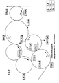
- the invention is described below using an exemplary embodiment shown in the schematic drawing in FIG. 1.
- the inking unit exists from an ink fountain 1, a film roller 2, a metering roller 3 for transferring a primary ink stream, the axis of which can be set against the film roller 2 to change the metering gap 4, an application roller 5, a friction roller 6 for transferring a secondary ink stream, a transfer roller 7 and a smoothing roller 8 Furthermore, a color return device is provided, which in the exemplary embodiment is a spiral roller 9, which returns excess ink, which comes from the ink flow reaction from the application roller 5, to the ink fountain 1.
- the inking unit works in a known manner with co-rotating and counter-rotating rollers that have different speeds.
- the metering roller 3 running in the same direction as the film roller runs counter to the direction of rotation of the application roller 5.
- the film roller 2 which preferably has a large diameter compared to the metering roller, preferably rotates slowly in order to avoid excessive flexing of the ink in the ink fountain.
- the flexing work of the paint can advantageously be further restricted in that the downwardly inclined paint box 1 is provided with an aperture 10 on which the ink knife 11 is arranged.
- the metering roller 3 preferably rotates much more slowly than the film roller in order to largely avoid the generation of frictional heat on the opposing application roller 5.
- the application roller 5 with a diameter which is considerably larger than that of the metering roller rotates at a considerably higher speed than the metering roller 3. As a result, the primary ink stream transferred from the metering roller is greatly stretched.
- a secondary ink stream is passed through the transfer roller 7 from the film roller onto the friction roller 6 and from it onto the application roller 5.
- the starting point for the calculation of the rotational speeds of the rollers involved is the controllability of a uniform metering gap 4.
- stable metering gap ratios of up to 15 m ⁇ can be mastered due to their roundness and low heat coefficients.
- the continuous ink supply is determined by the peripheral speed of the film roller 2 with the ink knife 11 set to maximum ink consumption.
- the ink supply must be adjusted so that a bead of paint forms in front of the metering gap.
- the splitting of the ink flow can be controlled as desired, so that the major part of the ink flow is guided from the metering roller 3 to the opposing application roller 5.
- the resultant, almost homogeneous ink film is completely homogenized by the transfer of the secondary ink stream from the rubbing roller 6, which smooths the ink film at the same time, and the subsequent smoothing roller 8, and is transferred from the application roller 5 to the printing cylinder, not shown.
- a metering gap setting of 100 m ⁇ results in an ink application of approximately 2.03 m ⁇ on the printing substrate.
- the back calculation shows that small changes in the ink layer thickness on the substrate can be made by a relatively large change in the metering gap setting, that is, relatively coarse adjustments of the metering gap enable finest changes in the ink layer thickness on the substrate.
- the scraped-off ink is taken over by a spiral roller 9, which runs counter to the metering roller 3 and is provided with two spirals or screw flights extending from the inside to the outside, from the ink bead which arises before the gap between the application roller 5 and the metering roller 3 and is conveyed to the outside, where it is taken from two outer rings of the film roller 2, the diameter of which is larger than that of the film roller 2, and returned to the ink fountain by means of scrapers.
- the above-mentioned arrangement allows a homogeneous color film to be rebuilt without retroactive effect.
Landscapes
- Inking, Control Or Cleaning Of Printing Machines (AREA)
- Coating Apparatus (AREA)
- Impression-Transfer Materials And Handling Thereof (AREA)
Applications Claiming Priority (2)
| Application Number | Priority Date | Filing Date | Title |
|---|---|---|---|
| DE3923037A DE3923037A1 (de) | 1989-07-13 | 1989-07-13 | Farbzonenfreies, verkuerztes farbwerk |
| DE3923037 | 1989-07-13 |
Publications (2)
| Publication Number | Publication Date |
|---|---|
| EP0407708A2 true EP0407708A2 (fr) | 1991-01-16 |
| EP0407708A3 EP0407708A3 (en) | 1991-07-17 |
Family
ID=6384875
Family Applications (1)
| Application Number | Title | Priority Date | Filing Date |
|---|---|---|---|
| EP19900109317 Withdrawn EP0407708A3 (en) | 1989-07-13 | 1990-05-17 | Short inking device without inking zones |
Country Status (8)
| Country | Link |
|---|---|
| EP (1) | EP0407708A3 (fr) |
| JP (1) | JPH0351132A (fr) |
| AU (1) | AU5683290A (fr) |
| CA (1) | CA2019899C (fr) |
| DE (1) | DE3923037A1 (fr) |
| FI (1) | FI903517A7 (fr) |
| NZ (1) | NZ234488A (fr) |
| ZA (1) | ZA904266B (fr) |
Cited By (3)
| Publication number | Priority date | Publication date | Assignee | Title |
|---|---|---|---|---|
| GB2327380A (en) * | 1997-07-18 | 1999-01-27 | Roland Man Druckmasch | Short inking unit |
| EP0974460A1 (fr) * | 1998-06-23 | 2000-01-26 | FGD, Forschungsgesellschaft Druckmaschinen e.V. | Procédé et dispositif pour réguler le transfert de l'encre dans un appareil d'encrage |
| WO2003072266A1 (fr) * | 2002-02-27 | 2003-09-04 | 3M Innovative Properties Company | Dispositif et procede d'enrobage de torons |
Families Citing this family (2)
| Publication number | Priority date | Publication date | Assignee | Title |
|---|---|---|---|---|
| DE10020510A1 (de) * | 2000-04-26 | 2001-11-15 | Roland Man Druckmasch | Dosiersystem zum Einfärben von Walzen in einer Druckmaschine |
| JP2010107538A (ja) * | 2008-10-28 | 2010-05-13 | Seiko Epson Corp | 現像装置、画像形成装置、及び、現像方法 |
Family Cites Families (10)
| Publication number | Priority date | Publication date | Assignee | Title |
|---|---|---|---|---|
| BE792367A (fr) * | 1971-12-06 | 1973-03-30 | Vickers Ltd | |
| US4041864A (en) * | 1972-05-09 | 1977-08-16 | Dahlgren Manufacturing Company | Method and apparatus for inking printing plates |
| DE2438169C3 (de) * | 1974-08-08 | 1978-04-20 | Maschinenfabrik Augsburg-Nuernberg Ag, 8900 Augsburg | Rotations-Offsetdruckwerk, bei dem eine Übertragungswalze des Farbwerkes mit einer profilierten Mantelfläche versehen ist |
| DE2659557A1 (de) * | 1976-12-30 | 1978-07-06 | Maschf Augsburg Nuernberg Ag | Rotations-offsetdruckwerk |
| US4208963A (en) * | 1978-04-18 | 1980-06-24 | Dahlgren Manufacturing Company | Newspaper printing system |
| DD140440A1 (de) * | 1978-10-28 | 1980-03-05 | Horst Schulz | Farbwerk fuer druckmaschinen |
| DE3008981A1 (de) * | 1980-03-08 | 1981-09-24 | M.A.N.- Roland Druckmaschinen AG, 6050 Offenbach | Umstellbares heber-/filmfarbwerk |
| DD201423A1 (de) * | 1981-10-02 | 1983-07-20 | Peter Straube | Farbwerk fuer druckmaschinen |
| FR2590205A1 (fr) * | 1985-11-21 | 1987-05-22 | Seailles Tison Sa | Dispositif pour l'encrage d'une forme d'impression rotative a partir d'une masse compacte d'encre a viscosite elevee |
| DE3804204A1 (de) * | 1988-02-11 | 1989-08-24 | Heidelberger Druckmasch Ag | Filmfarbwerk fuer rotationsdruckmaschinen |
-
1989
- 1989-07-13 DE DE3923037A patent/DE3923037A1/de active Granted
-
1990
- 1990-05-17 EP EP19900109317 patent/EP0407708A3/de not_active Withdrawn
- 1990-06-04 ZA ZA904266A patent/ZA904266B/xx unknown
- 1990-06-06 AU AU56832/90A patent/AU5683290A/en not_active Abandoned
- 1990-06-26 CA CA002019899A patent/CA2019899C/fr not_active Expired - Fee Related
- 1990-07-11 FI FI903517A patent/FI903517A7/fi not_active IP Right Cessation
- 1990-07-12 JP JP2182885A patent/JPH0351132A/ja active Pending
- 1990-07-13 NZ NZ234488A patent/NZ234488A/en unknown
Cited By (6)
| Publication number | Priority date | Publication date | Assignee | Title |
|---|---|---|---|---|
| GB2327380A (en) * | 1997-07-18 | 1999-01-27 | Roland Man Druckmasch | Short inking unit |
| GB2327380B (en) * | 1997-07-18 | 2002-02-20 | Roland Man Druckmasch | Short inking unit |
| EP0974460A1 (fr) * | 1998-06-23 | 2000-01-26 | FGD, Forschungsgesellschaft Druckmaschinen e.V. | Procédé et dispositif pour réguler le transfert de l'encre dans un appareil d'encrage |
| WO2003072266A1 (fr) * | 2002-02-27 | 2003-09-04 | 3M Innovative Properties Company | Dispositif et procede d'enrobage de torons |
| US6926772B2 (en) | 2002-02-27 | 2005-08-09 | 3M Innovative Properties Company | Strand coating device and method |
| US7329435B2 (en) | 2002-02-27 | 2008-02-12 | 3M Innovative Properties Company | Strand coating device and method |
Also Published As
| Publication number | Publication date |
|---|---|
| CA2019899A1 (fr) | 1991-01-13 |
| NZ234488A (en) | 1992-01-29 |
| ZA904266B (en) | 1991-03-27 |
| FI903517A0 (fi) | 1990-07-11 |
| AU5683290A (en) | 1991-01-17 |
| FI903517A7 (fi) | 1991-01-14 |
| JPH0351132A (ja) | 1991-03-05 |
| DE3923037A1 (de) | 1991-01-24 |
| DE3923037C2 (fr) | 1993-05-27 |
| EP0407708A3 (en) | 1991-07-17 |
| CA2019899C (fr) | 1999-03-30 |
Similar Documents
| Publication | Publication Date | Title |
|---|---|---|
| DE3338143C2 (de) | Verfahren zur Erzeugung einer dem Druckbild entsprechenden Farbschichtstärke im Farbwerk einer Druckmaschine | |
| DE3228002C2 (de) | Vorrichtung zum Aufbringen eines sehr gleichmäßigen und glatten Überzugs auf der Oberfläche einer zylindrischen Walze | |
| DE2916047C2 (de) | Farb- und Feuchtwerk für lithographische Druckplatten | |
| EP0003790A1 (fr) | Dispositif pour enduire une feuille en mouvement | |
| DE2557551B1 (de) | Verfahren und vorrichtung zum auftragen von fluessigkeiten, insbesondere von fluessigen klebstoffen auf bahnfoermiges material | |
| DE8413874U1 (de) | Vorrichtung zum Befeuchten an lithographischen Druckpressen | |
| DE3804204C2 (fr) | ||
| DE2062276A1 (de) | Farbwerk fur eine Rotationsdruckmaschine | |
| EP1282517B1 (fr) | Procede et dispositif pour appliquer une couche de vernis sur la face superieure d'un support d'impression | |
| DE1940661B2 (de) | Feuereinrichtung fur hthogra phische Druckmaschinen | |
| DE3923037C2 (fr) | ||
| DE3641213C2 (de) | Druckeinheit einer Offsetrotationsdruckmaschine | |
| EP0210671B1 (fr) | Dispositif de mouillage pour machine à imprimer | |
| EP1291176B1 (fr) | Machine à imprimer et procédé d'opération d'un dispositif d'encrage | |
| DE2913825C2 (fr) | ||
| EP0056067B1 (fr) | Dispositif pour appliquer une couche mince d'une substance d'enduction sur une bande de matériau en mouvement | |
| DE3127880C2 (de) | Farbwerk | |
| DD202663A5 (de) | Farbwerk fuer eine lithographische druckmaschine | |
| DE3927365A1 (de) | Auftragswerk zum auftragen von beschichtungen | |
| EP4180228B1 (fr) | Dispositif pour appliquer un fluide | |
| EP3960463B1 (fr) | Matage au moyen du processus de transfert | |
| DE202008000451U1 (de) | Beschichtungsdüse, Beschichtungsanordnung mit der Beschichtungsdüse | |
| DE20320598U1 (de) | Dosiereinrichtung für Farben und Lacke | |
| AT201995B (de) | Verfahren und Vorrichtung zur Herstellung von Mehrfarbenschichtblöcken | |
| AT40010B (de) | Verfahren zur Regelung der Farbzufuhr bei Farbwerken. |
Legal Events
| Date | Code | Title | Description |
|---|---|---|---|
| PUAI | Public reference made under article 153(3) epc to a published international application that has entered the european phase |
Free format text: ORIGINAL CODE: 0009012 |
|
| 17P | Request for examination filed |
Effective date: 19900517 |
|
| AK | Designated contracting states |
Kind code of ref document: A2 Designated state(s): AT BE CH DK FR GB IT LI NL SE |
|
| PUAL | Search report despatched |
Free format text: ORIGINAL CODE: 0009013 |
|
| AK | Designated contracting states |
Kind code of ref document: A3 Designated state(s): AT BE CH DK FR GB IT LI NL SE |
|
| STAA | Information on the status of an ep patent application or granted ep patent |
Free format text: STATUS: THE APPLICATION IS DEEMED TO BE WITHDRAWN |
|
| 18D | Application deemed to be withdrawn |
Effective date: 19921201 |